Side mirror MITSUBISHI LANCER 2005 User Guide
[x] Cancel search | Manufacturer: MITSUBISHI, Model Year: 2005, Model line: LANCER, Model: MITSUBISHI LANCER 2005Pages: 788, PDF Size: 45.98 MB
Page 386 of 788
DOOR MIRROR
EXTERIOR51-48
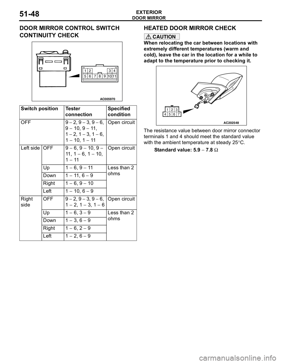
DOOR MIRROR CONTROL SWITCH
CONTINUITY CHECKHEATED DOOR MIRROR CHECK
CAUTION
When relocating the car between locations with
extremely different temperatures (warm and
cold), leave the car in the location for a while to
adapt to the temperature prior to checking it.
The resistance value between door mirror connector
terminals 1 and 4 should meet the standard value
with the ambient temperature at steady 25°C.
Standard value: 5.9 − 7.8 Ω Switch position Tester
connectionSpecified
condition
OFF 9 − 2, 9 − 3, 9 − 6,
9 − 10, 9 − 11 ,
1 − 2, 1 − 3, 1 − 6,
1 − 10, 1 − 11Open circuit
Left side OFF 9 − 6, 9 − 10, 9 −
11 , 1 − 6, 1 − 10,
1 − 11Open circuit
Up 1 − 6, 9 − 11 Less than 2
ohms
Down 1 − 11 , 6 − 9
Right 1 − 6, 9 − 10
Left 1 − 10, 6 − 9
Right
sideOFF 9 − 2, 9 − 3, 9 − 6,
1 − 2, 1 − 3, 1 − 6Open circuit
Up 1 − 6, 3 − 9 Less than 2
ohms
Down 1 − 3, 6 − 9
Right 1 − 6, 2 − 9
Left 1 − 2, 6 − 9
AC005970
2
14 3
5109
8
7 611
AC202548
1
456723
Page 622 of 788
DASH PANEL
CONFIGURATION DIAGRAMS80-16
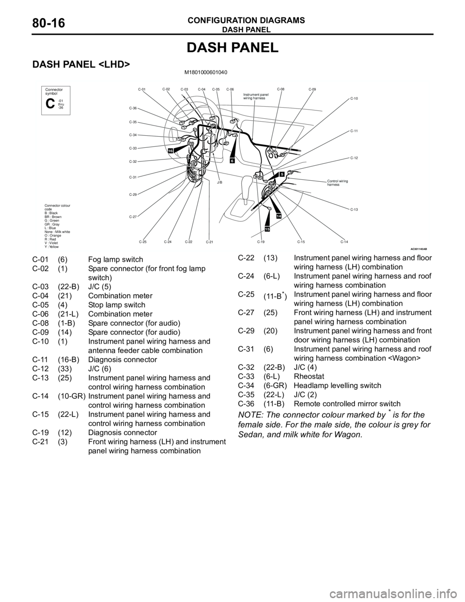
DASH PANEL
DASH PANEL
NOTE: The connector colour marked by * is for the
female side. For the male side, the colour is grey for
Sedan, and milk white for Wagon.
AC301140
16
C-06
C-05 C-02
C-01
C-34
C-32
C-31
C-29
C-27
C-25C-24C-22
C-21 Connector colour
code
B : Black
BR : Brown
G : Green
GR : Gray
L : Blue
None : Milk white
O : Orange
R : Red
V : Violet
Y : YellowConnector
symbol
-01
thru
-36C
C-04 C-03
C-36
C-33
C-35
6
J/B
AB
5
14
15
C-08
C-09
C-11
C-12 C-10
C-14
C-15
C-13
Instrument panel
wiring harness
Control wiring
harness
C-19
C-01 (6) Fog lamp switch
C-02 (1) Spare connector (for front fog lamp
switch)
C-03 (22-B) J/C (5)
C-04 (21) Combination meter
C-05 (4) Stop lamp switch
C-06 (21-L) Combination meter
C-08 (1-B) Spare connector (for audio)
C-09 (14) Spare connector (for audio)
C-10 (1) Instrument panel wiring harness and
antenna feeder cable combination
C-11 (16-B) Diagnosis connector
C-12 (33) J/C (6)
C-13 (25) Instrument panel wiring harness and
control wiring harness combination
C-14 (10-GR) Instrument panel wiring harness and
control wiring harness combination
C-15 (22-L) Instrument panel wiring harness and
control wiring harness combination
C-19 (12) Diagnosis connector
C-21 (3) Front wiring harness (LH) and instrument
panel wiring harness combinationC-22 (13) Instrument panel wiring harness and floor
wiring harness (LH) combination
C-24 (6-L) Instrument panel wiring harness and roof
wiring harness combination
C-25
(11-B
*)Instrument panel wiring harness and floor
wiring harness (LH) combination
C-27 (25) Front wiring harness (LH) and instrument
panel wiring harness combination
C-29 (20) Instrument panel wiring harness and front
door wiring harness (LH) combination
C-31 (6) Instrument panel wiring harness and roof
wiring harness combination
C-32 (22-B) J/C (4)
C-33 (6-L) Rheostat
C-34 (6-GR) Headlamp levelling switch
C-35 (22-L) J/C (2)
C-36 (11-B) Remote controlled mirror switch
Page 632 of 788
DOOR
CONFIGURATION DIAGRAMS80-26
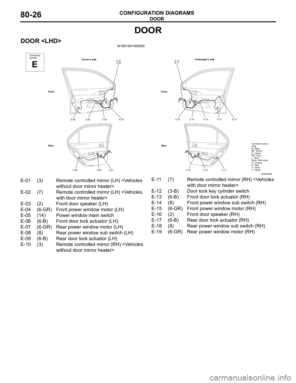
DOOR
DOOR
AC304415
Connector
symbol
E
Driver's sideE-01
E-02
E-03
E-04
E-05 E-06
E-07
E-08 E-09
Front
RearPassenger's side
E-10
E-11
E-12
E-14
E-15 E-16
E-17
E-18 E-19
Front
Rear
AB
E-13
Connector colour
code
B : Black
BR : Brown
G : Green
GR : Gray
L : Blue
None : Milk white
O : Orange
R : Red
V : Violet
Y : Yellow
E-01 (3) Remote controlled mirror (LH)
E-02 (7) Remote controlled mirror (LH)
E-03 (2) Front door speaker (LH)
E-04 (6-GR) Front power window motor (LH)
E-05 (14) Power window main switch
E-06 (6-B) Front door lock actuator (LH)
E-07 (6-GR) Rear power window motor (LH)
E-08 (8) Rear power window sub switch (LH)
E-09 (6-B) Rear door lock actuator (LH)
E-10 (3) Remote controlled mirror (RH)
E-12 (3-B) Door lock key cylinder switch
E-13 (6-B) Front door lock actuator (RH)
E-14 (8) Front power window sub switch (RH)
E-15 (6-GR) Front power window motor (RH)
E-16 (2) Front door speaker (RH)
E-17 (6-B) Rear door lock actuator (RH)
E-18 (8) Rear power window sub switch (RH)
E-19 (6-GR) Rear power window motor (RH)
Page 633 of 788
DOOR
CONFIGURATION DIAGRAMS80-27
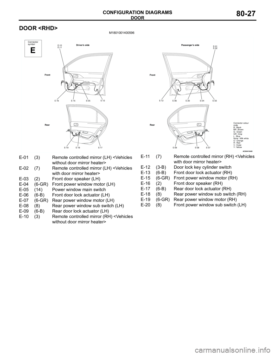
DOOR
AC304416
Connector
symbol
E
Driver's sideE-10
E-11
E-13
E-05
E-15 E-16
E-17
E-18 E-19
Front
RearPassenger's side
E-01
E-02
E-03
E-04
E-20 E-06
E-07
E-08 E-09
Front
Rear
AB
E-12
Connector colour
code
B : Black
BR : Brown
G : Green
GR : Gray
L : Blue
None : Milk white
O : Orange
R : Red
V : Violet
Y : Yellow
E-01 (3) Remote controlled mirror (LH)
E-02 (7) Remote controlled mirror (LH)
E-03 (2) Front door speaker (LH)
E-04 (6-GR) Front power window motor (LH)
E-05 (14) Power window main switch
E-06 (6-B) Front door lock actuator (LH)
E-07 (6-GR) Rear power window motor (LH)
E-08 (8) Rear power window sub switch (LH)
E-09 (6-B) Rear door lock actuator (LH)
E-10 (3) Remote controlled mirror (RH)
E-12 (3-B) Door lock key cylinder switch
E-13 (6-B) Front door lock actuator (RH)
E-15 (6-GR) Front power window motor (RH)
E-16 (2) Front door speaker (RH)
E-17 (6-B) Rear door lock actuator (RH)
E-18 (8) Rear power window sub switch (RH)
E-19 (6-GR) Rear power window motor (RH)
E-20 (8) Front power window sub switch (LH)
Page 650 of 788
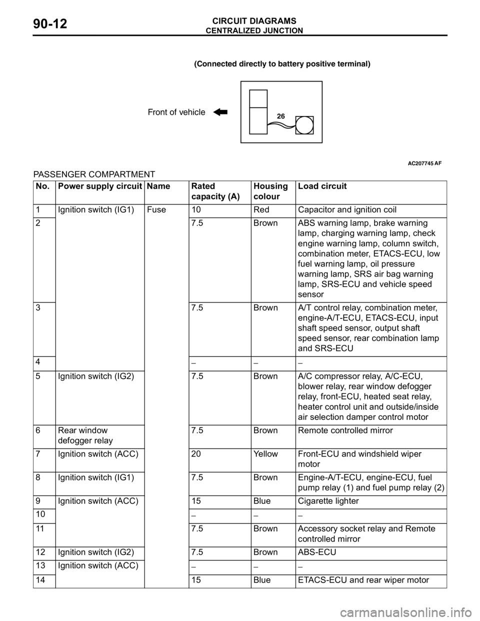
CENTRALIZED JUNCTION
CIRCUIT DIAGRAMS90-12
PASSENGER COMPARTMENT
AC207745
(Connected directly to battery positive terminal)
Front of vehicle26
AF
No. Power supply circuit Name Rated
capacity (A)Housing
colourLoad circuit
1 Ignition switch (IG1) Fuse 10 Red Capacitor and ignition coil
2 7.5 Brown ABS warning lamp, brake warning
lamp, charging warning lamp, check
engine warning lamp, column switch,
combination meter, ETACS-ECU, low
fuel warning lamp, oil pressure
warning lamp, SRS air bag warning
lamp, SRS-ECU and vehicle speed
sensor
3 7.5 Brown A/T control relay, combination meter,
engine-A/T-ECU, ETACS-ECU, input
shaft speed sensor, output shaft
speed sensor, rear combination lamp
and SRS-ECU
4
−−−
5 Ignition switch (IG2) 7.5 Brown A/C compressor relay, A/C-ECU,
blower relay, rear window defogger
relay, front-ECU, heated seat relay,
heater control unit and outside/inside
air selection damper control motor
6 Rear window
defogger relay7.5 Brown Remote controlled mirror
7 Ignition switch (ACC) 20 Yellow Front-ECU and windshield wiper
motor
8 Ignition switch (IG1) 7.5 Brown Engine-A/T-ECU, engine-ECU, fuel
pump relay (1) and fuel pump relay (2)
9 Ignition switch (ACC) 15 Blue Cigarette lighter
10
−−−
11 7.5 Brown Accessory socket relay and Remote
controlled mirror
12 Ignition switch (IG2) 7.5 Brown ABS-ECU
13 Ignition switch (ACC)
−−−
14 15 Blue ETACS-ECU and rear wiper motor
Page 749 of 788
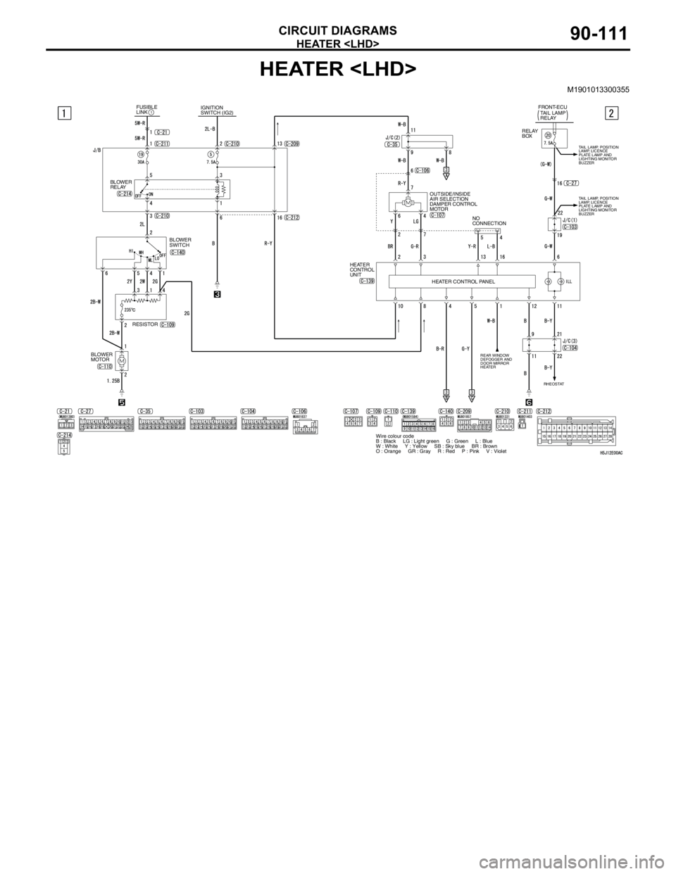
HEATER
CIRCUIT DIAGRAMS90-111
HEATER
M1901013300355
HEATER CONTROL PANELRELAY
BOX
OUTSIDE/INSIDE
AIR SELECTION
DAMPER CONTROL
MOTORTAIL LAMP
RELAY
REAR WINDOW
DEFOGGER AND
DOOR MIRROR
HEATER
FRONT-ECU
HEATER
CONTROL
UNIT
RHEOSTAT
Wire colour code
B : Black LG : Light green G : Green L : Blue
W : White Y : Yellow SB : Sky blue BR : Brown
O : Orange GR : Gray R : Red P : Pink V : Violet
TAIL LAMP, POSITION
LAMP, LICENCE
PLATE LAMP AND
LIGHTING MONITOR
BUZZER
NO
CONNECTION
TAIL LAMP, POSITION
LAMP, LICENCE
PLATE LAMP AND
LIGHTING MONITOR
BUZZER
IGNITION
SWITCH (IG2) FUSIBLE
LINK1
BLOWER
RELAY
BLOWER
SWITCH
RESISTOR
BLOWER
MOTOR
Page 751 of 788

HEATER
CIRCUIT DIAGRAMS90-113
HEATER
M1901013300366
HEATER CONTROL PANEL OUTSIDE/INSIDE
AIR SELECTION
DAMPER CONTROL
MOTORTAIL LAMP
RELAY FRONT-ECU
HEATER
CONTROL
UNIT
RHEOSTAT
Wire colour code
B : Black LG : Light green G : Green L : Blue W : White Y : Yellow SB : Sky blue
BR : Brown O : Orange GR : Gray R : Red P : Pink V : Violet RELAY
BOX
TAIL LAMP, POSITION
LAMP, LICENCE
PLATE LAMP AND
LIGHTING MONITOR
BUZZER
NO
CONNECTION IGNITION
SWITCH (IG2) FUSIBLE
LINK
1
BLOWER
RELAY
BLOWER
SWITCH
RESISTOR
BLOWER
MOTOR
REAR WINDOW
DEFOGGER AND
DOOR MIRROR
HEATER
Page 753 of 788
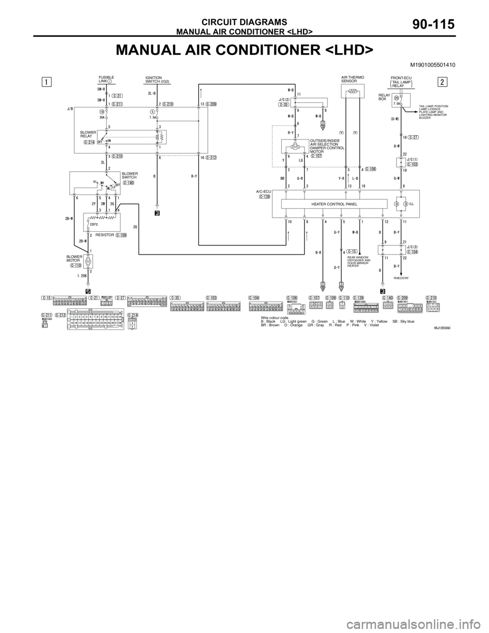
MANUAL AIR CONDITIONER
CIRCUIT DIAGRAMS90-115
MANUAL AIR CONDITIONER
M1901005501410
REAR WINDOW
DEFOGGER AND
DOOR MIRROR
HEATER
IGNITION
SWITCH (IG2) FUSIBLE
LINK1
BLOWER
RELAY
BLOWER
SWITCH
RESISTOR
BLOWER
MOTORHEATER CONTROL PANEL OUTSIDE/INSIDE
AIR SELECTION
DAMPER CONTROL
MOTORTAIL LAMP
RELAY FRONT-ECU
A/C-ECU
RHEOSTAT
Wire colour code
B : Black LG : Light green G : Green L : Blue W : White Y : Yellow SB : Sky blue
BR : Brown O : Orange GR : Gray R : Red P : Pink V : Violet AIR THERMO
SENSOR
RELAY
BOX
TAIL LAMP, POSITION
LAMP, LICENCE
PLATE LAMP AND
LIGHTING MONITOR
BUZZER
Page 755 of 788
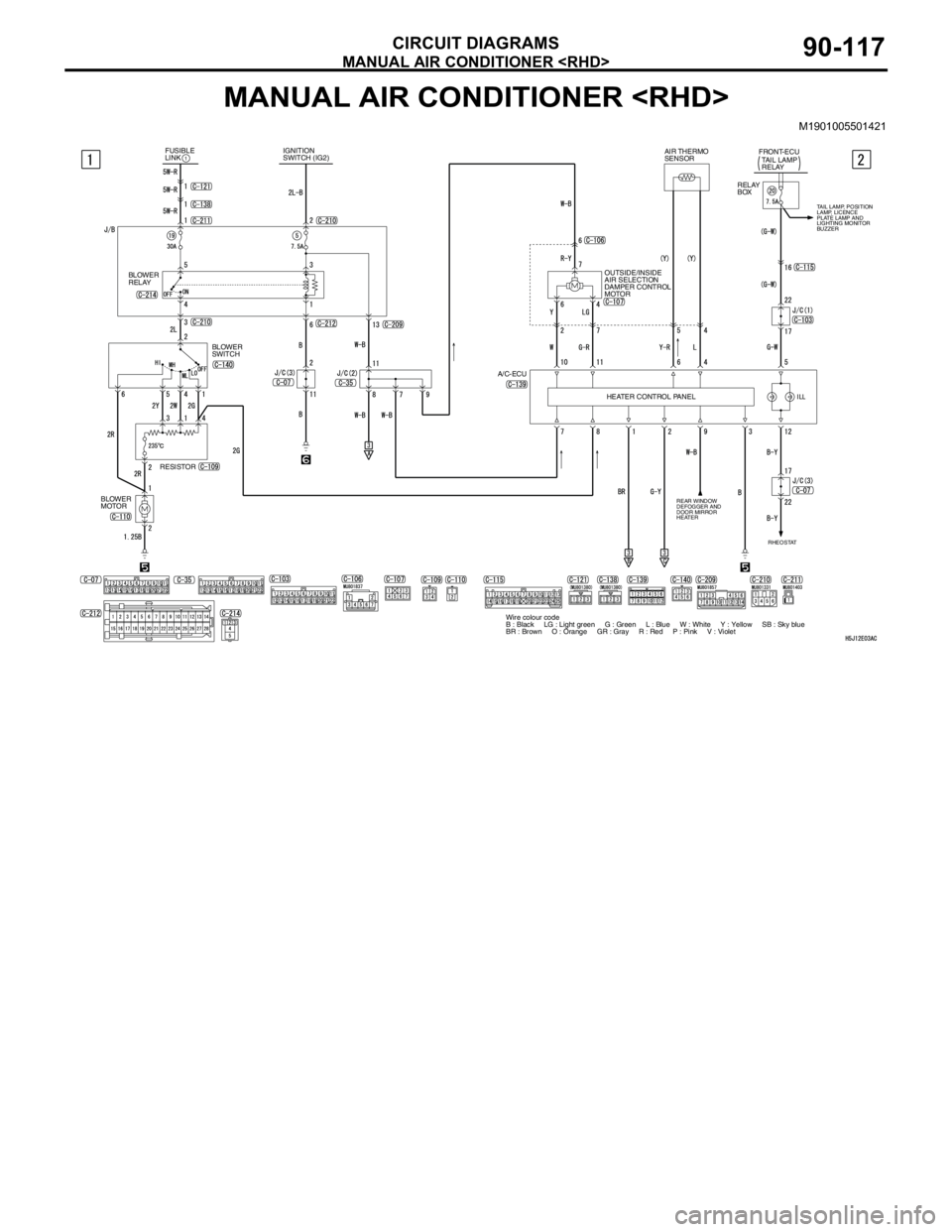
MANUAL AIR CONDITIONER
CIRCUIT DIAGRAMS90-117
MANUAL AIR CONDITIONER
M1901005501421
REAR WINDOW
DEFOGGER AND
DOOR MIRROR
HEATER
IGNITION
SWITCH (IG2) FUSIBLE
LINK1
BLOWER
RELAY
BLOWER
SWITCH
RESISTOR
BLOWER
MOTORHEATER CONTROL PANEL OUTSIDE/INSIDE
AIR SELECTION
DAMPER CONTROL
MOTORTAIL LAMP
RELAY FRONT-ECU
A/C-ECU
RHEOSTAT
Wire colour code
B : Black LG : Light green G : Green L : Blue W : White Y : Yellow SB : Sky blue
BR : Brown O : Orange GR : Gray R : Red P : Pink V : Violet
TAIL LAMP, POSITION
LAMP, LICENCE
PLATE LAMP AND
LIGHTING MONITOR
BUZZER
AIR THERMO
SENSOR
RELAY
BOX