height MITSUBISHI LANCER 2005 User Guide
[x] Cancel search | Manufacturer: MITSUBISHI, Model Year: 2005, Model line: LANCER, Model: MITSUBISHI LANCER 2005Pages: 788, PDF Size: 45.98 MB
Page 320 of 788

TRUNK LID
BODY42-42
3. If there is a difference in height between the side
outer panels and the side edges of the trunk lid
panel assembly, check the trunk lid hinges and, if
necessary, replace them
4. If the clearance around the trunk lid panel
assembly is not uniform, and the trunk lid can be
locked and unlocked smoothly, make adjustments
to the trunk lid bumpers (refer to P.42-42) and
trunk lid hinges (Refer to P.42-42).
5. If the locking and unlocking of the trunk lid still is
difficult after making the above adjustments,
adjust the trunk lid striker (Refer to P.42-42).
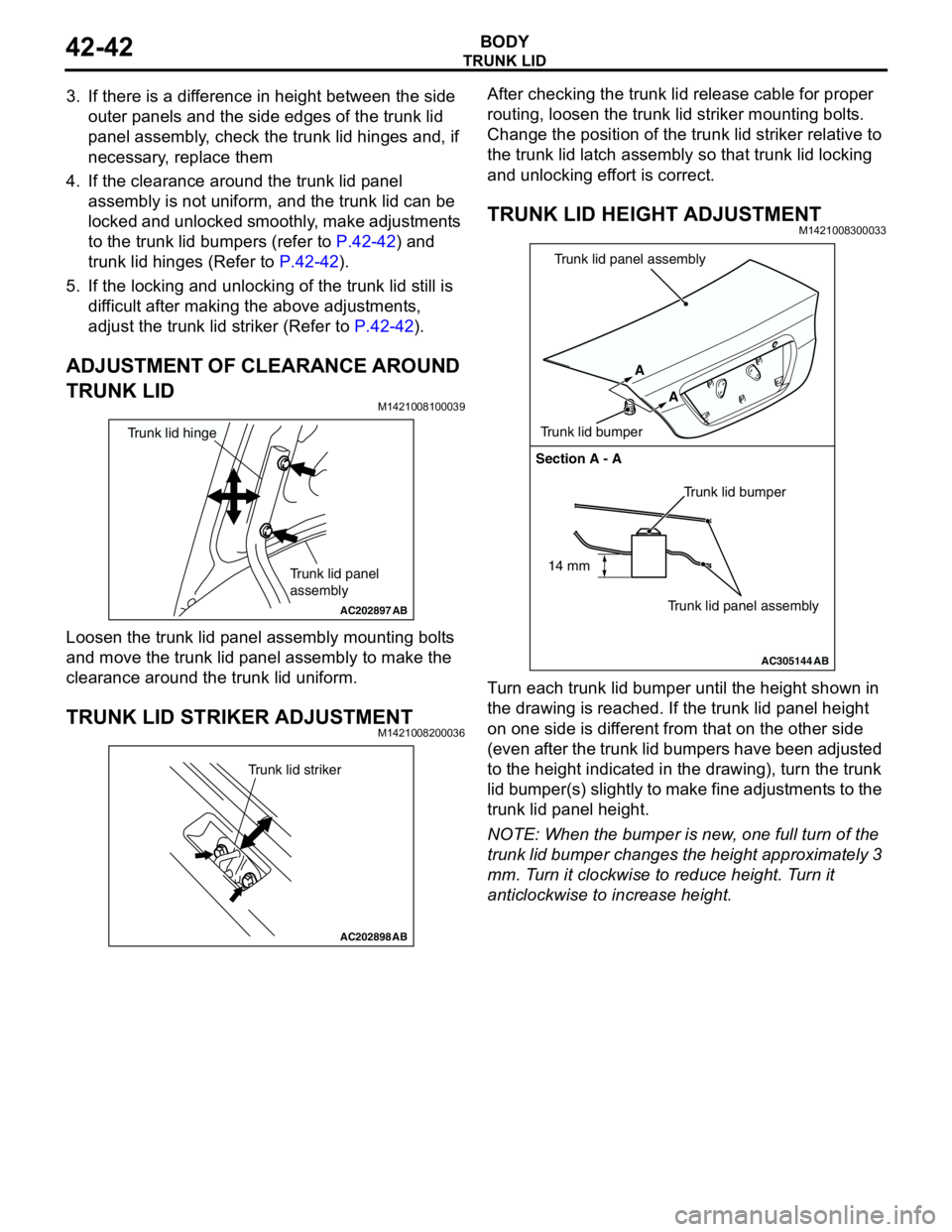
ADJUSTMENT OF CLEARANCE AROUND
TRUNK LID
M1421008100039
Loosen the trunk lid panel assembly mounting bolts
and move the trunk lid panel assembly to make the
clearance around the trunk lid uniform.
TRUNK LID STRIKER ADJUSTMENTM1421008200036
After checking the trunk lid release cable for proper
routing, loosen the trunk lid striker mounting bolts.
Change the position of the trunk lid striker relative to
the trunk lid latch assembly so that trunk lid locking
and unlocking effort is correct.
TRUNK LID HEIGHT ADJUSTMENTM1421008300033
Turn each trunk lid bumper until the height shown in
the drawing is reached. If the trunk lid panel height
on one side is different from that on the other side
(even after the trunk lid bumpers have been adjusted
to the height indicated in the drawing), turn the trunk
lid bumper(s) slightly to make fine adjustments to the
trunk lid panel height.
NOTE: When the bumper is new, one full turn of the
trunk lid bumper changes the height approximately 3
mm. Turn it clockwise to reduce height. Turn it
anticlockwise to increase height.
AC202897
Trunk lid panel
assembly
Trunk lid hinge
AB
AC202898
Trunk lid striker
AB
AC305144
Section A - A
Trunk lid bumper
Trunk lid panel assembly A
A
Trunk lid bumperTrunk lid panel assembly
AB
14 mm
Page 417 of 788

COMBINATION METER ASSEMBLY
CHASSIS ELECTRICAL54A-29
COMBINATION METER ASSEMBLY
SERVICE SPECIFICATIONSM1543000300324
SEALANTM1543024600028
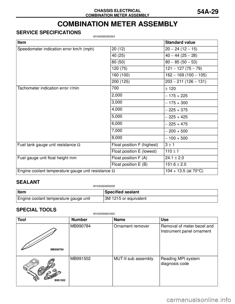
SPECIAL TOOLSM1543000601652
ItemStandard value
Speedometer indication error km/h (mph) 20 (12) 20 − 24 (12 − 15)
40 (25) 40 − 44 (25 − 28)
80 (50) 80 − 85 (50 − 53)
120 (75) 121 − 127 (75 − 79)
160 (100) 162 − 169 (100 − 105)
200 (125) 203 − 211 (126 − 131)
Tachometer indication error r/min 700
± 120
2,000
− 175 + 225
3,000
− 175 + 300
4,000
− 225 + 375
5,000
− 225 + 425
6,000
− 225 + 475
7,000
− 200 + 500
8,000
− 100 + 500
Fuel tank gauge unit resistance ΩFloat position F (highest) 3 ± 1
Float position E (lowest) 110 ± 1
Fuel gauge unit float height mm Float position F (A) 24.1 ± 2.0
Float position E (B) 151.6 ± 2.0
Engine coolant temperature gauge unit resistance Ω104 + 13.5 (at 70°C)
Item Specified sealant
Engine coolant temperature gauge unit 3M 1215 or equivalent
Tool Number Name Use
MB990784 Ornament remover Removal of meter bezel and
Instrument panel ornament
MB991502 MUT-II sub assembly Reading MPI system
diagnosis code
MB990784
B991502
Page 449 of 788

COMBINATION METER ASSEMBLY
CHASSIS ELECTRICAL54A-61
NOTE: For tachometer check, use an external
high quality inductive tachometer.
2. Compare the readings of the vehicle tachometer
and the external tachometer at every engine
speed, and check if the variations are within the
standard values.
Standard values:
FUEL TANK GAUGE UNIT CHECKM1543001200461
Remove the fuel tank gauge unit. (Refer to GROUP
13C, Fuel Tank P.13C-4.)
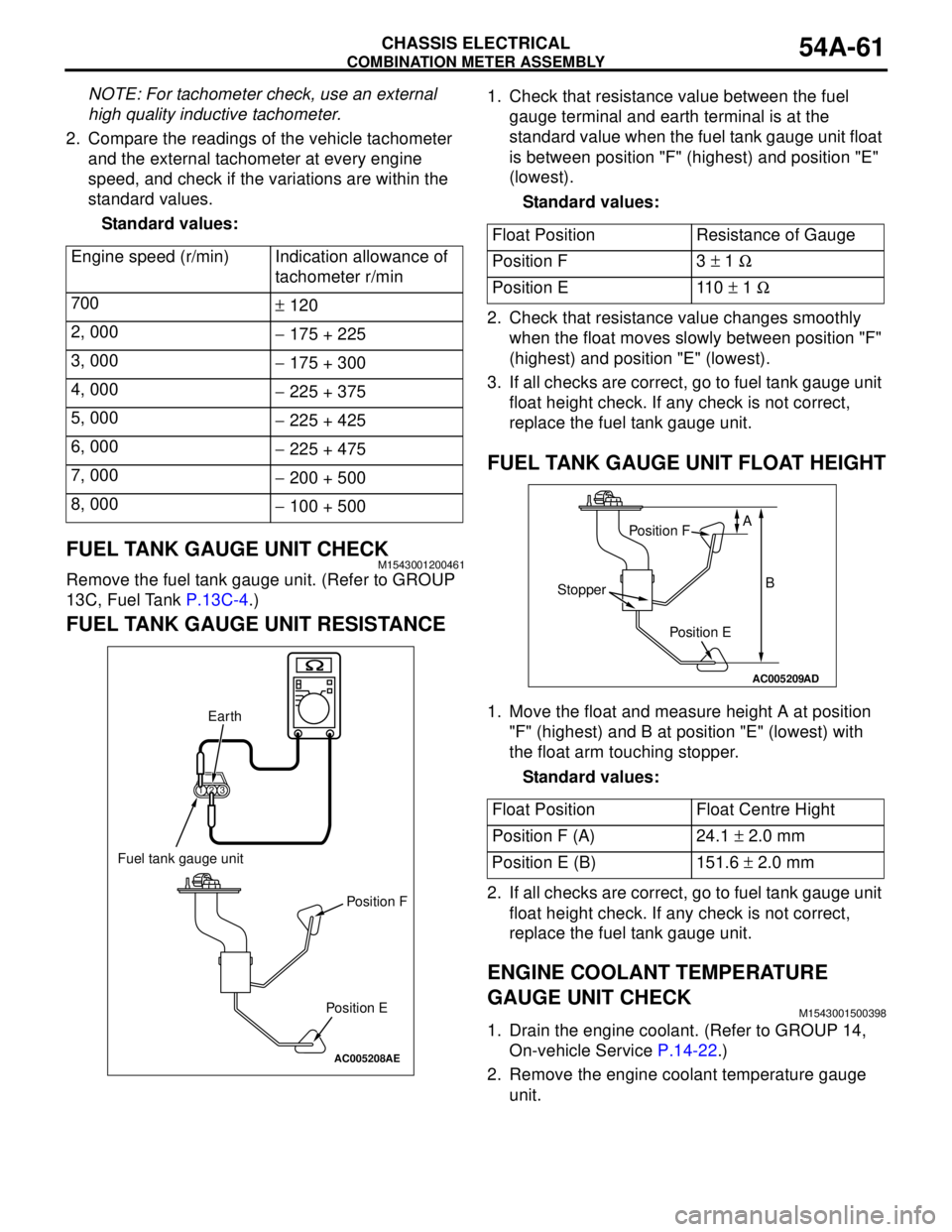
FUEL TANK GAUGE UNIT RESISTANCE
1. Check that resistance value between the fuel
gauge terminal and earth terminal is at the
standard value when the fuel tank gauge unit float
is between position "F" (highest) and position "E"
(lowest).
Standard values:
2. Check that resistance value changes smoothly
when the float moves slowly between position "F"
(highest) and position "E" (lowest).
3. If all checks are correct, go to fuel tank gauge unit
float height check. If any check is not correct,
replace the fuel tank gauge unit.
FUEL TANK GAUGE UNIT FLOAT HEIGHT
1. Move the float and measure height A at position
"F" (highest) and B at position "E" (lowest) with
the float arm touching stopper.
Standard values:
2. If all checks are correct, go to fuel tank gauge unit
float height check. If any check is not correct,
replace the fuel tank gauge unit.
ENGINE COOLANT TEMPERATURE
GAUGE UNIT CHECK
M1543001500398
1. Drain the engine coolant. (Refer to GROUP 14,
On-vehicle Service P.14-22.)
2. Remove the engine coolant temperature gauge
unit. Engine speed (r/min) Indication allowance of
tachometer r/min
700
± 120
2, 000
− 175 + 225
3, 000
− 175 + 300
4, 000
− 225 + 375
5, 000
− 225 + 425
6, 000
− 225 + 475
7, 000
− 200 + 500
8, 000
− 100 + 500
AC005208
123
AE
Fuel tank gauge unit
Earth
Position F
Position E
Float Position Resistance of Gauge
Position F 3 ± 1 Ω
Position E 110 ± 1 Ω
Float Position Float Centre Hight
Position F (A) 24.1 ± 2.0 mm
Position E (B) 151.6 ± 2.0 mm
AC005209
AD
Position F
Position E
Stopper
A
B
Page 455 of 788

HEADLAMP
CHASSIS ELECTRICAL54A-67
NOTE: Height from the floor to the centre of
the headlamps (Reference value): 840 mm
(3) Measure the distance from the centre line of
the vehicle to the centre of each headlamp.
Transfer the measurement to the screen.
Vertical tape or mark on the screen with
reference to the centre line of each headlamp
bulb.
HEADLAMP ADJUSTMENT
CAUTION
•Do not cover a headlamp for more than three
minutes to prevent the plastic headlamp lens
deformation.
•When adjusting one headlamp beam, make
sure that another headlamp is off by
disconnecting the connector from it. When
reconnecting the connector, make sure that
the headlamp beam is not disturbed
accidentally.
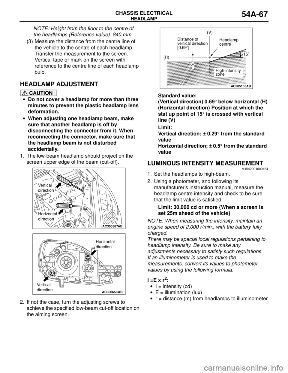
1. The low-beam headlamp should project on the
screen upper edge of the beam (cut-off).
2. If not the case, turn the adjusting screws to
achieve the specified low-beam cut-off location on
the aiming screen.Standard value:
(Vertical direction) 0.69° below horizontal (H)
(Horizontal direction) Position at which the
stat up point of 15° is crossed with vertical
line (V)
Limit:
Vertical direction; ± 0.29° from the standard
value
Horizontal direction; ± 0.5° from the standard
value
LUMINOUS INTENSITY MEASUREMENTM1542001000464
1. Set the headlamps to high-beam.
2. Using a photometer, and following its
manufacturer's instruction manual, measure the
headlamp centre intensity and check to be sure
that the limit value is satisfied.
Limit: 30,000 cd or more {When a screen is
set 25m ahead of the vehicle}
NOTE: When measuring the intensity, maintain an
engine speed of 2,000 r/min., with the battery fully
charged.
There may be special local regulations pertaining to
headlamp intensity. Be sure to make any
adjustments necessary to satisfy such regulations.
If an illuminometer is used to make the
measurements, convert its values to photometer
values by using the following formula.
I =E x r
2:
•I = intensity (cd)
•E = illumination (lux)
•r = distance (m) from headlamps to illuminometer
AC300567AB
Vertical
direction
Horizontal
direction
AC300658AB
Vertical
direction
Horizontal
direction
AC305155
(H)(V)
Distance of
vertical direction
[0.69˚]Headlamp
centre
High intensity
zone
15˚
AB