check MITSUBISHI LANCER 2005 Workshop Manual
[x] Cancel search | Manufacturer: MITSUBISHI, Model Year: 2005, Model line: LANCER, Model: MITSUBISHI LANCER 2005Pages: 788, PDF Size: 45.98 MB
Page 462 of 788
FOG LAMP
CHASSIS ELECTRICAL54A-74
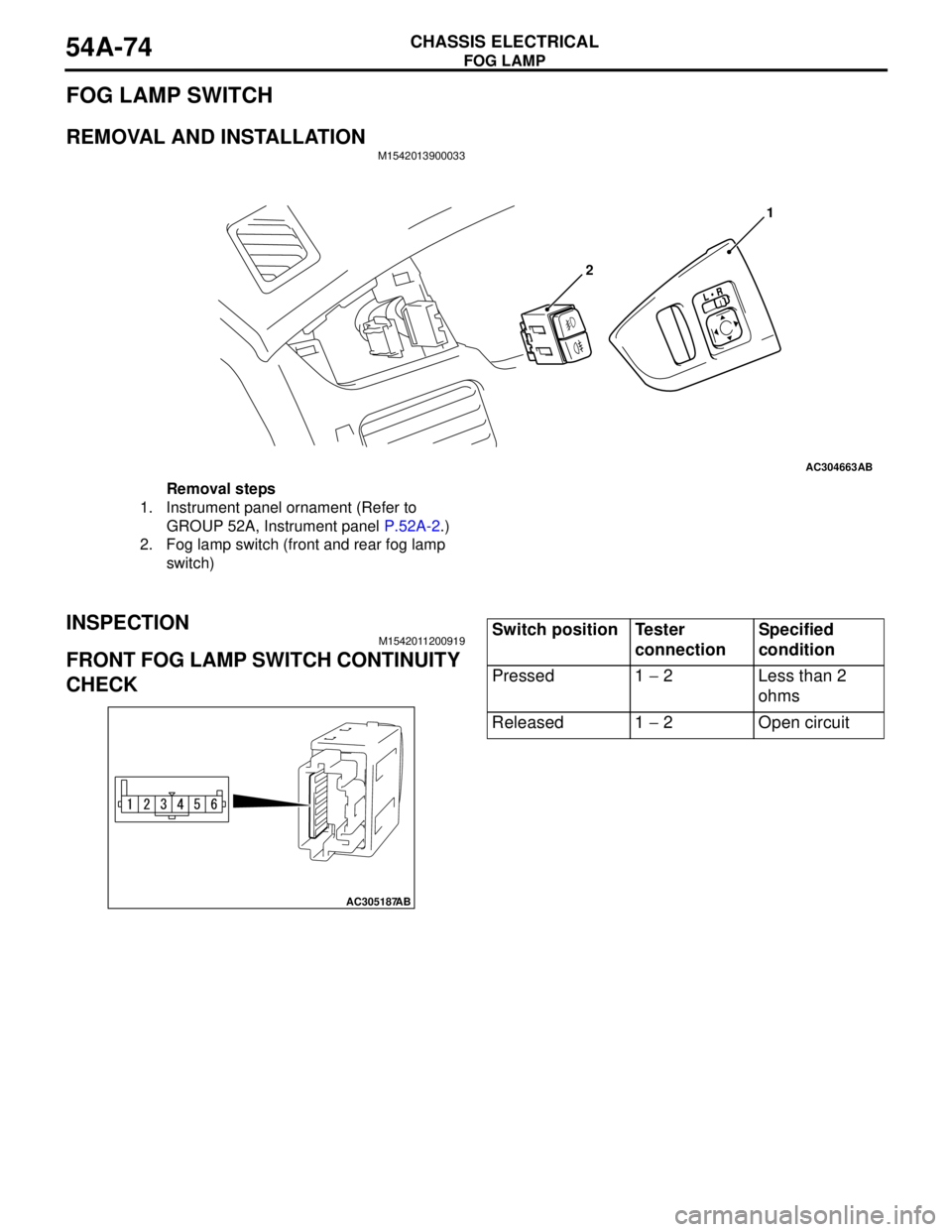
FOG LAMP SWITCH
REMOVAL AND INSTALLATIONM1542013900033
INSPECTIONM1542011200919
FRONT FOG LAMP SWITCH CONTINUITY
CHECK
AC304663AB
21
Removal steps
1. Instrument panel ornament (Refer to
GROUP 52A, Instrument panel P.52A-2.)
2. Fog lamp switch (front and rear fog lamp
switch)
AC305187
AB
Switch position Tester
connectionSpecified
condition
Pressed 1 − 2 Less than 2
ohms
Released 1 − 2 Open circuit
Page 463 of 788
REAR FOG LAMP
CHASSIS ELECTRICAL54A-75
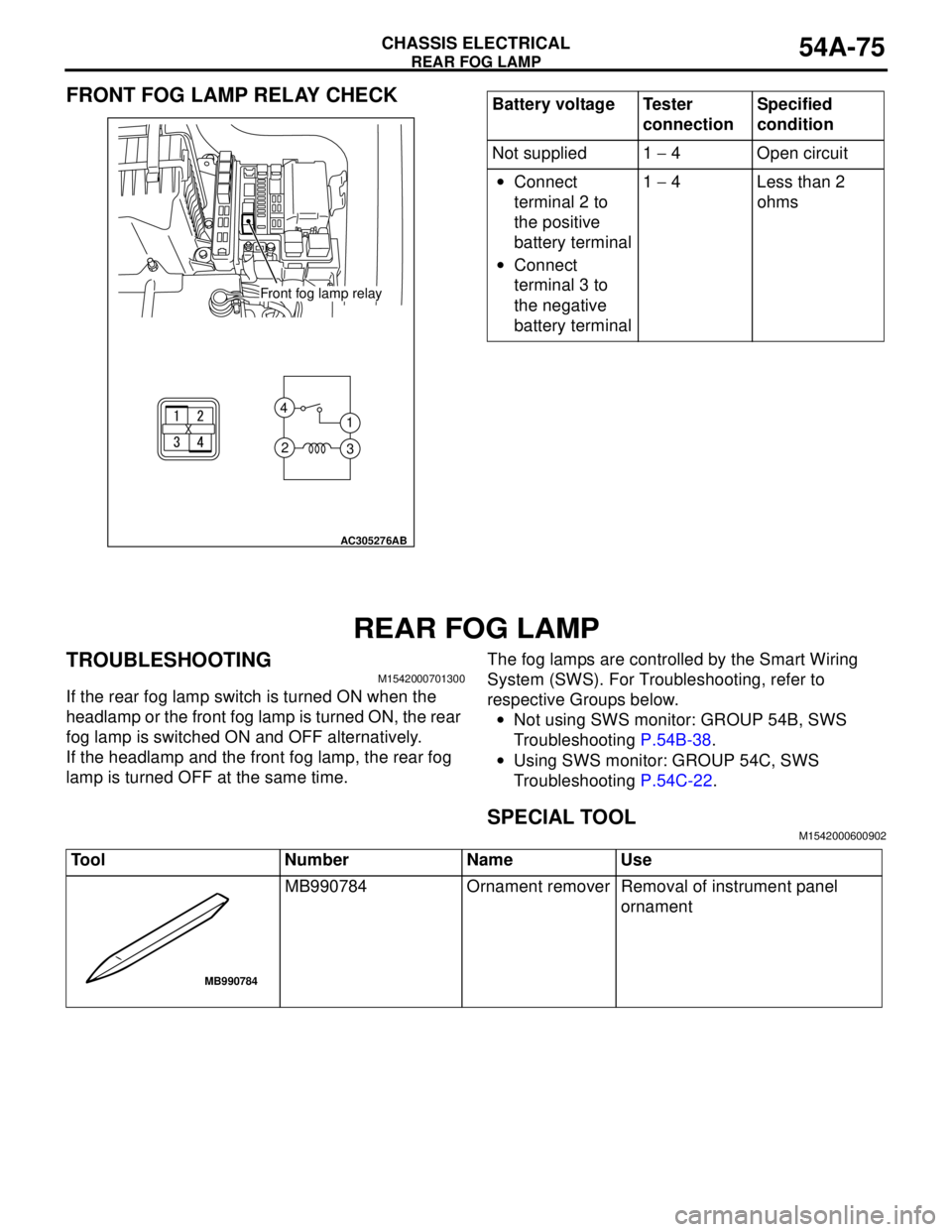
FRONT FOG LAMP RELAY CHECK
REAR FOG LAMP
TROUBLESHOOTINGM1542000701300
If the rear fog lamp switch is turned ON when the
headlamp or the front fog lamp is turned ON, the rear
fog lamp is switched ON and OFF alternatively.
If the headlamp and the front fog lamp, the rear fog
lamp is turned OFF at the same time.The fog lamps are controlled by the Smart Wiring
System (SWS). For Troubleshooting, refer to
respective Groups below.
•Not using SWS monitor: GROUP 54B, SWS
Troubleshooting P.54B-38.
•Using SWS monitor: GROUP 54C, SWS
Troubleshooting P.54C-22.
SPECIAL TOOLM1542000600902
1 4
3 2
AC305276
AB
Front fog lamp relay
Battery voltage Tester
connectionSpecified
condition
Not supplied 1 − 4 Open circuit
•Connect
terminal 2 to
the positive
battery terminal
•Connect
terminal 3 to
the negative
battery terminal1 − 4 Less than 2
ohms
Tool Number Name Use
MB990784 Ornament remover Removal of instrument panel
ornament
MB990784
Page 464 of 788
REAR FOG LAMP
CHASSIS ELECTRICAL54A-76
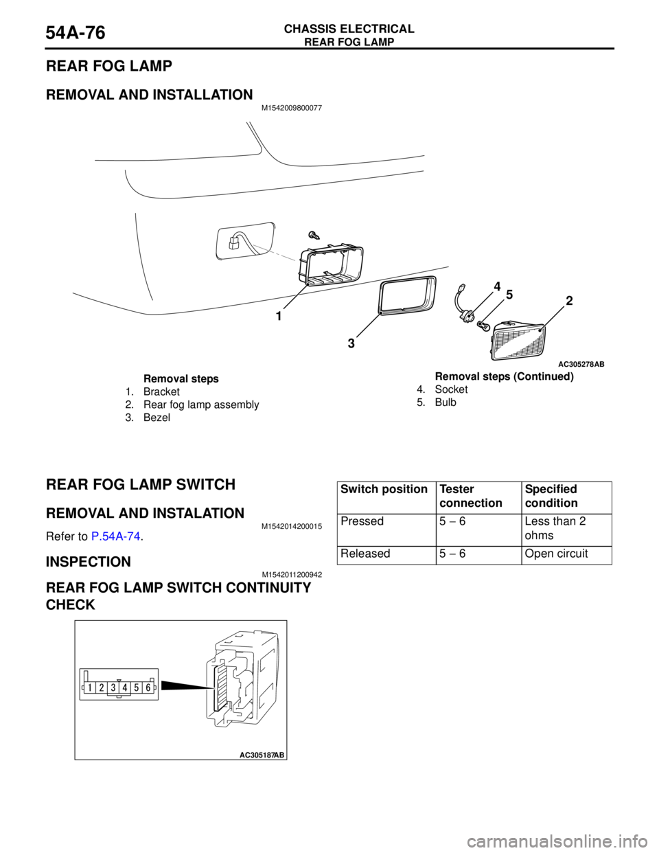
REAR FOG LAMP
REMOVAL AND INSTALLATIONM1542009800077
REAR FOG LAMP SWITCH
REMOVAL AND INSTALATIONM1542014200015
Refer to P.54A-74.
INSPECTIONM1542011200942
REAR FOG LAMP SWITCH CONTINUITY
CHECK
AC305278AB
32
1
4
5
Removal steps
1. Bracket
2. Rear fog lamp assembly
3. Bezel4. Socket
5. BulbRemoval steps (Continued)
AC305187
AB
Switch position Tester
connectionSpecified
condition
Pressed 5 − 6 Less than 2
ohms
Released 5 − 6 Open circuit
Page 465 of 788
SIDE TURN-SIGNAL LAMP
CHASSIS ELECTRICAL54A-77
FRONT FOG LAMP RELAY CHECK
SIDE TURN-SIGNAL LAMP
SPECIAL TOOLM1542000600913
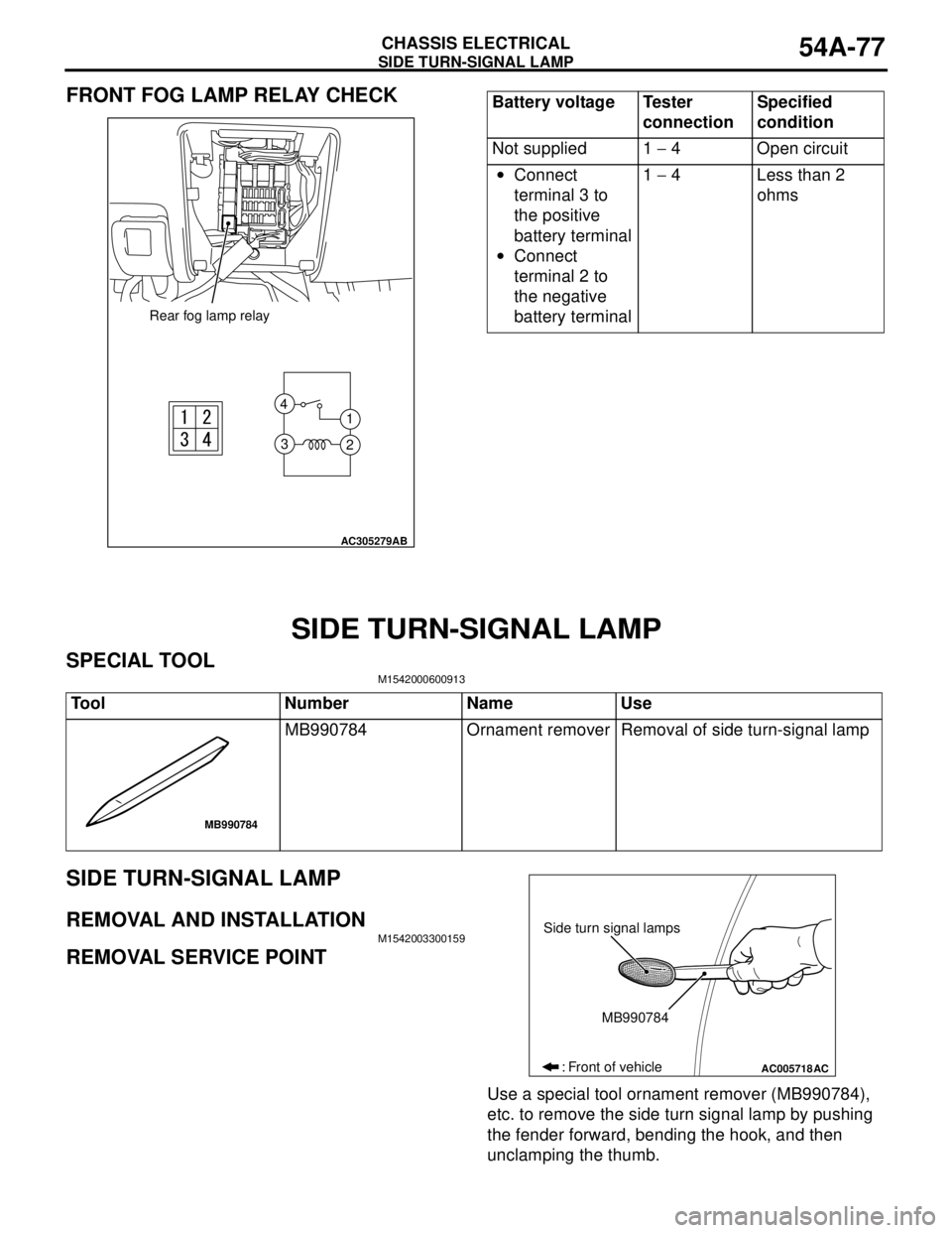
SIDE TURN-SIGNAL LAMP
REMOVAL AND INSTALLATIONM1542003300159
REMOVAL SERVICE POINT
Use a special tool ornament remover (MB990784),
etc. to remove the side turn signal lamp by pushing
the fender forward, bending the hook, and then
unclamping the thumb.
AC305279
1 4
3
2
AB
Rear fog lamp relay
Battery voltage Tester
connectionSpecified
condition
Not supplied 1 − 4 Open circuit
•Connect
terminal 3 to
the positive
battery terminal
•Connect
terminal 2 to
the negative
battery terminal1 − 4 Less than 2
ohms
Tool Number Name Use
MB990784 Ornament remover Removal of side turn-signal lamp
MB990784
AC005718
Side turn signal lamps
MB990784
: Front of vehicle
AC
Page 474 of 788
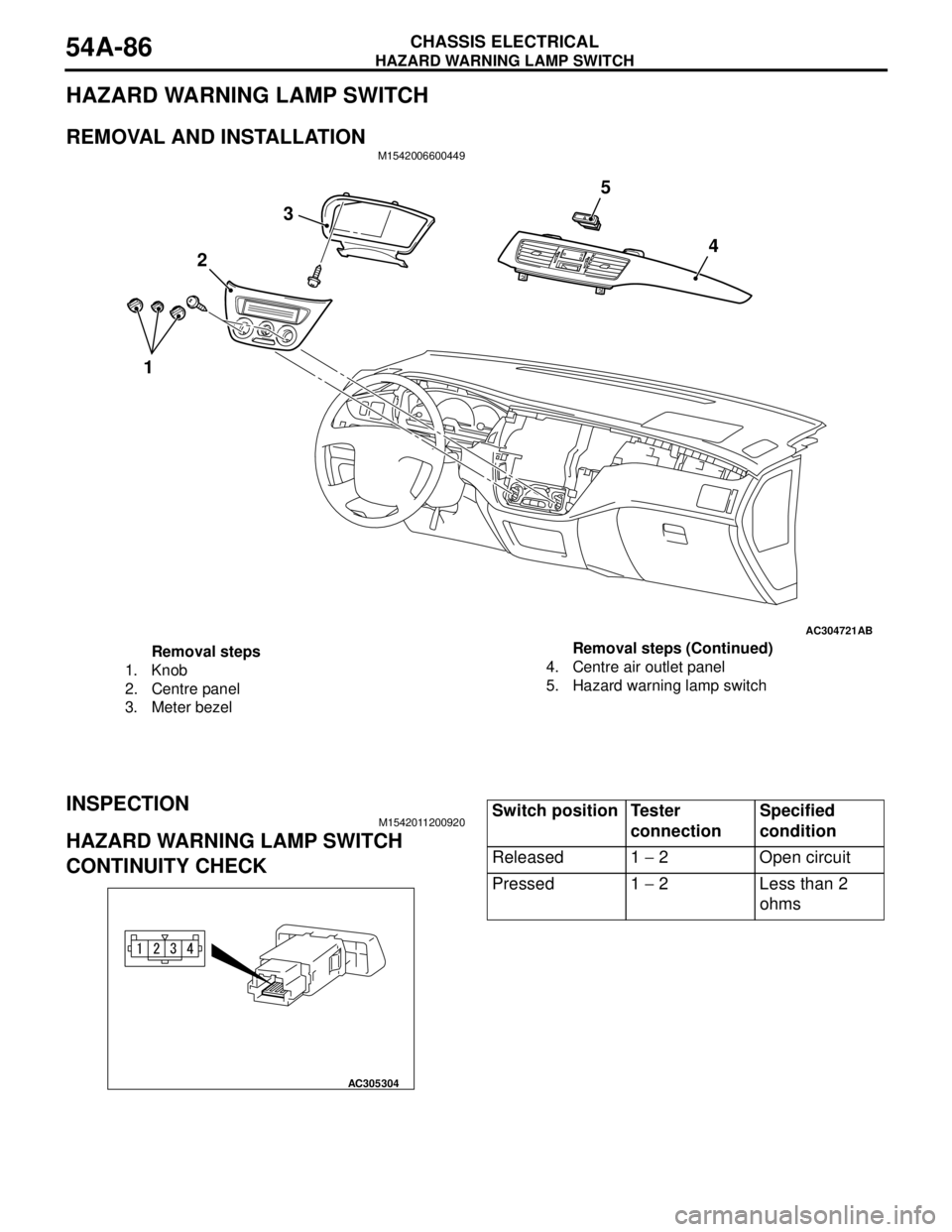
HAZARD WARNING LAMP SWITCH
CHASSIS ELECTRICAL54A-86
HAZARD WARNING LAMP SWITCH
REMOVAL AND INSTALLATIONM1542006600449
INSPECTIONM1542011200920
HAZARD WARNING LAMP SWITCH
CONTINUITY CHECK
AC304721AB
3
4
2
15
Removal steps
1. Knob
2. Centre panel
3. Meter bezel4. Centre air outlet panel
5. Hazard warning lamp switchRemoval steps (Continued)
AC305304
Switch position Tester
connectionSpecified
condition
Released 1 − 2 Open circuit
Pressed 1 − 2 Less than 2
ohms
Page 476 of 788
COLUMN SWITCH
CHASSIS ELECTRICAL54A-88
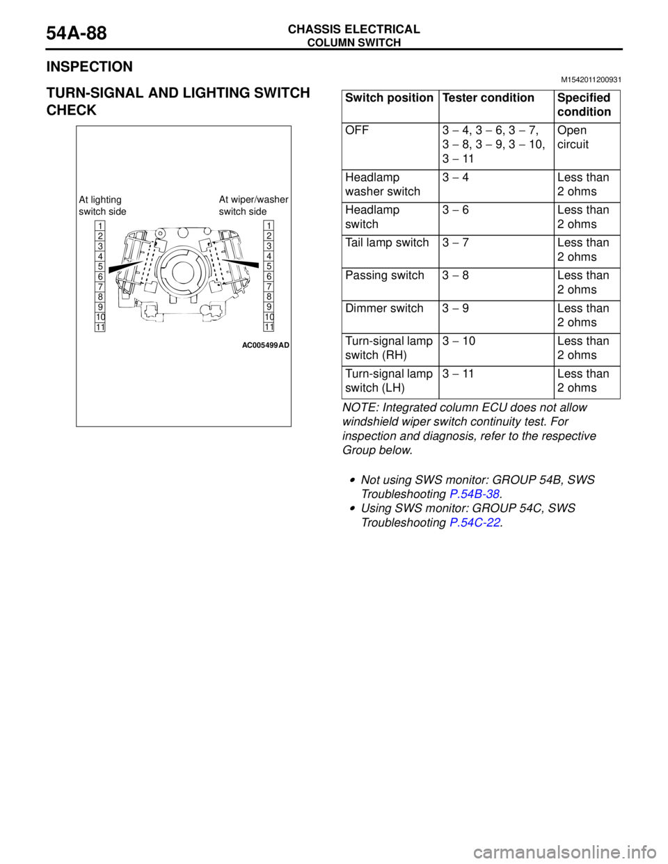
INSPECTIONM1542011200931
TURN-SIGNAL AND LIGHTING SWITCH
CHECK
NOTE: Integrated column ECU does not allow
windshield wiper switch continuity test. For
inspection and diagnosis, refer to the respective
Group below.
.
•Not using SWS monitor: GROUP 54B, SWS
Troubleshooting P.54B-38.
•Using SWS monitor: GROUP 54C, SWS
Troubleshooting P.54C-22.
1
6
8
11 109 7 5 4 3 21
6
8
11 109 7 5 4
3
2
AC005499
At lighting
switch sideAt wiper/washer
switch side
AD
Switch position Tester condition Specified
condition
OFF 3 − 4, 3 − 6, 3 − 7,
3 − 8, 3 − 9, 3 − 10,
3 − 11Open
circuit
Headlamp
washer switch3 − 4 Less than
2 ohms
Headlamp
switch3 − 6 Less than
2 ohms
Tail lamp switch 3 − 7 Less than
2 ohms
Passing switch 3 − 8 Less than
2 ohms
Dimmer switch 3 − 9 Less than
2 ohms
Turn-signal lamp
switch (RH)3 − 10 Less than
2 ohms
Turn-signal lamp
switch (LH)3 − 11 Less than
2 ohms
Page 477 of 788
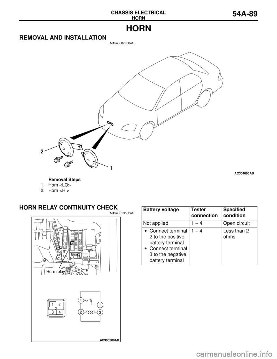
HORN
CHASSIS ELECTRICAL54A-89
HORN
REMOVAL AND INSTALLATIONM1543007900413
HORN RELAY CONTINUITY CHECKM1543019502418
AC304666AB
1 2
Removal Steps
1. Horn
2. Horn
AC305306
1 4
3 2
AB
Horn relay
Battery voltage Tester
connectionSpecified
condition
Not applied 1 − 4 Open circuit
•Connect terminal
2 to the positive
battery terminal
•Connect terminal
3 to the negative
battery terminal1 − 4 Less than 2
ohms
Page 479 of 788
CIGARETTE LIGHTER
CHASSIS ELECTRICAL54A-91
CIGARETTE LIGHTER
INSPECTIONM1543005700242
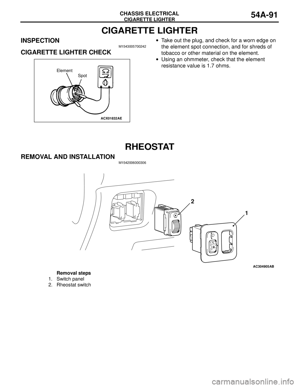
CIGARETTE LIGHTER CHECK
•Take out the plug, and check for a worn edge on
the element spot connection, and for shreds of
tobacco or other material on the element.
•Using an ohmmeter, check that the element
resistance value is 1.7 ohms.
RHEOSTAT
REMOVAL AND INSTALLATIONM1542006000306
ACX01832AE
Element
Spot
AC304905AB
2
1
Removal steps
1. Switch panel
2. Rheostat switch
Page 480 of 788
RHEOSTAT
CHASSIS ELECTRICAL54A-92
INSPECTIONM1542006100228
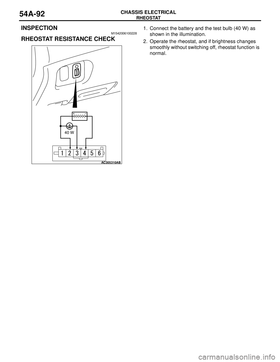
RHEOSTAT RESISTANCE CHECK
1. Connect the battery and the test bulb (40 W) as
shown in the illumination.
2. Operate the rheostat, and if brightness changes
smoothly without switching off, rheostat function is
normal.
AC305310
AB
40 W
Page 484 of 788
REAR WINDOW DEFOGGER
CHASSIS ELECTRICAL54A-96
ON-VEHICLE SERVICE
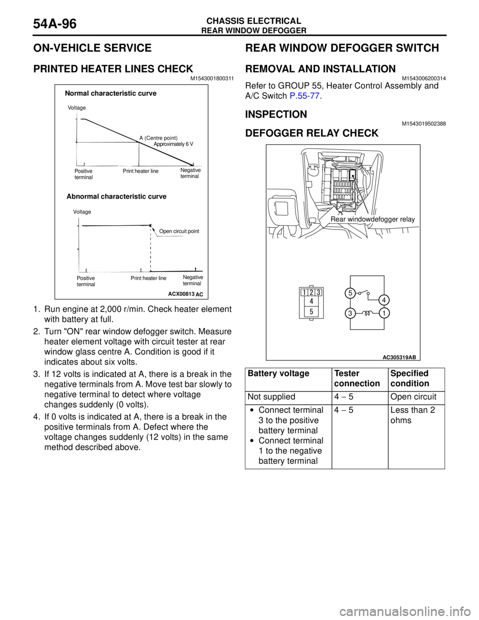
PRINTED HEATER LINES CHECKM1543001800311
1. Run engine at 2,000 r/min. Check heater element
with battery at full.
2. Turn "ON" rear window defogger switch. Measure
heater element voltage with circuit tester at rear
window glass centre A. Condition is good if it
indicates about six volts.
3. If 12 volts is indicated at A, there is a break in the
negative terminals from A. Move test bar slowly to
negative terminal to detect where voltage
changes suddenly (0 volts).
4. If 0 volts is indicated at A, there is a break in the
positive terminals from A. Defect where the
voltage changes suddenly (12 volts) in the same
method described above.
REAR WINDOW DEFOGGER SWITCH
REMOVAL AND INSTALLATIONM1543006200314
Refer to GROUP 55, Heater Control Assembly and
A/C Switch P.55-77.
INSPECTIONM1543019502388
DEFOGGER RELAY CHECK
ACX00813
Normal characteristic curve
Abnormal characteristic curve
A (Centre point)
Approximately 6 V
Negative
terminal Print heater line
Positive
terminal
Open circuit point Voltage
AC Voltage
Negative
terminal Print heater line
Positive
terminal
Battery voltage Tester
connectionSpecified
condition
Not supplied 4 − 5 Open circuit
•Connect terminal
3 to the positive
battery terminal
•Connect terminal
1 to the negative
battery terminal4 − 5 Less than 2
ohms
1 5
4
3
AC305319
AB
Rear windowdefogger relay