ECU MITSUBISHI LANCER 2005 Service Manual
[x] Cancel search | Manufacturer: MITSUBISHI, Model Year: 2005, Model line: LANCER, Model: MITSUBISHI LANCER 2005Pages: 788, PDF Size: 45.98 MB
Page 270 of 788
POWER STEERING GEAR BOX AND LINKAGE
POWER STEERING37-36
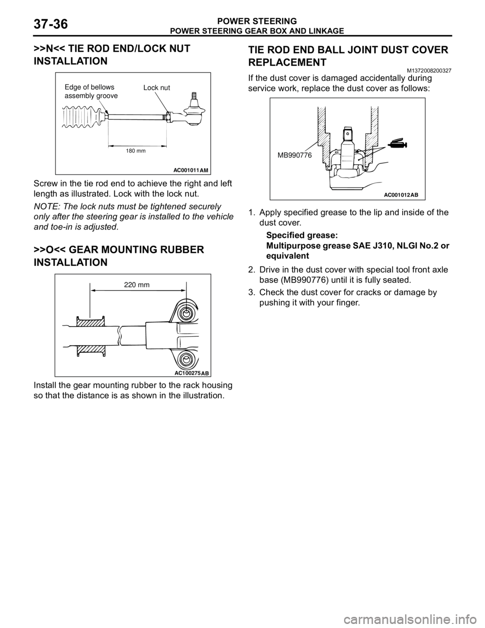
>>N<< TIE ROD END/LOCK NUT
INSTALLATION
Screw in the tie rod end to achieve the right and left
length as illustrated. Lock with the lock nut.
NOTE: The lock nuts must be tightened securely
only after the steering gear is installed to the vehicle
and toe-in is adjusted.
>>O<< GEAR MOUNTING RUBBER
INSTALLATION
Install the gear mounting rubber to the rack housing
so that the distance is as shown in the illustration.
TIE ROD END BALL JOINT DUST COVER
REPLACEMENT
M1372008200327
If the dust cover is damaged accidentally during
service work, replace the dust cover as follows:
1. Apply specified grease to the lip and inside of the
dust cover.
Specified grease:
Multipurpose grease SAE J310, NLGI No.2 or
equivalent
2. Drive in the dust cover with special tool front axle
base (MB990776) until it is fully seated.
3. Check the dust cover for cracks or damage by
pushing it with your finger.
AC001011
AM
Lock nut Edge of bellows
assembly groove
180 mm
AC100275
AB
220 mm
AC001012
AB
MB990776
Page 312 of 788
Page 315 of 788
DOOR
BODY42-37
INSTALLATION SERVICE POINTS
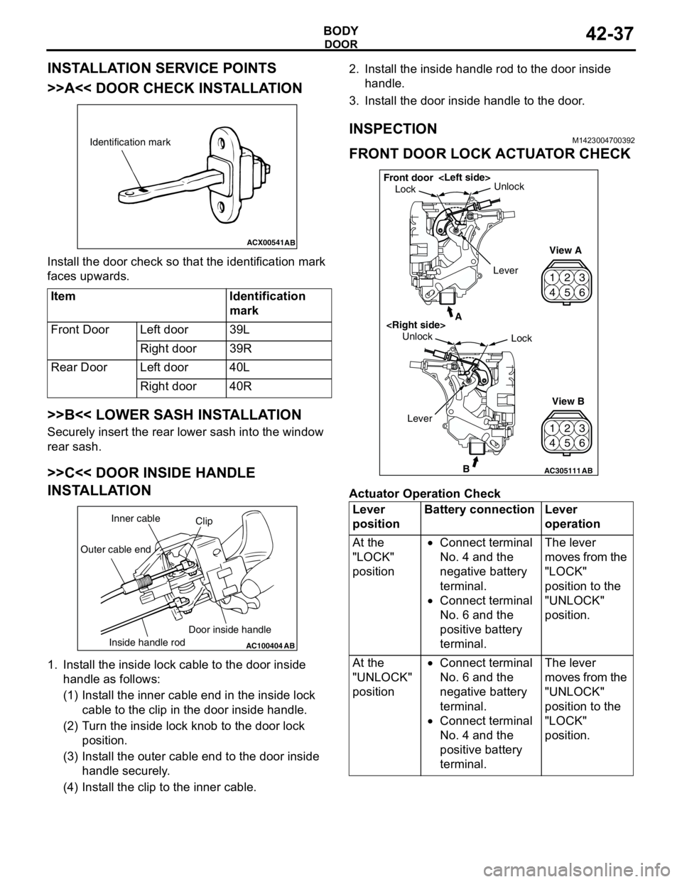
>>A<< DOOR CHECK INSTALLATION
Install the door check so that the identification mark
faces upwards.
>>B<< LOWER SASH INSTALLATION
Securely insert the rear lower sash into the window
rear sash.
>>C<< DOOR INSIDE HANDLE
INSTALLATION
1. Install the inside lock cable to the door inside
handle as follows:
(1) Install the inner cable end in the inside lock
cable to the clip in the door inside handle.
(2) Turn the inside lock knob to the door lock
position.
(3) Install the outer cable end to the door inside
handle securely.
(4) Install the clip to the inner cable.2. Install the inside handle rod to the door inside
handle.
3. Install the door inside handle to the door.
INSPECTIONM1423004700392
FRONT DOOR LOCK ACTUATOR CHECK
Actuator Operation Check Item Identification
mark
Front Door Left door 39L
Right door 39R
Rear Door Left door 40L
Right door 40R
ACX00541
Identification mark
AB
AC100404
AB
Clip Inner cable
Outer cable end
Inside handle rodDoor inside handleLever
positionBattery connection Lever
operation
At the
"LOCK"
position•Connect terminal
No. 4 and the
negative battery
terminal.
•Connect terminal
No. 6 and the
positive battery
terminal.The lever
moves from the
"LOCK"
position to the
"UNLOCK"
position.
At the
"UNLOCK"
position•Connect terminal
No. 6 and the
negative battery
terminal.
•Connect terminal
No. 4 and the
positive battery
terminal.The lever
moves from the
"UNLOCK"
position to the
"LOCK"
position.
42
53
6 1
42
53
6 1
AC305111B
A
AB
LockUnlock
View A
View B Unlock
Lock Front door
Lever
Page 331 of 788
KEYLESS ENTRY SYSTEM
BODY42-53
TROUBLESHOOTINGM1428000700287
The keyless entry system is controlled by the Smart
Wiring System (SWS). For troubleshooting, refer to
GROUP 54B, Troubleshooting P.54B-17 or GROUP
54C, Troubleshooting P.54C-4.
ON-VEHICLE SERVICE
KEYLESS ENTRY SYSTEM CHECKM1428001400096
Check the system as described below. If the system
does not work, carry out troubleshooting. Refer to
GROUP 54B, Troubleshooting P.54B-17, refer to
GROUP 54C, Troubleshooting P.54C-4.
•Operate the transmitter to check that the doors
and tailgate can be locked and unlocked.
•Operate the transmitter to check that the
answerback function works in response to door
and tailgate
NOTE: The adjustment function allows you to
change the answerback setting as follows. Prior
to that check, confirm which setting is activated.
.
•The hazard warning lamps flash twice when
locked and once when unlocked. The room
lamp flashes twice when locked and
illuminates for 15 seconds when unlocked.
•The hazard warning lamps do not flash when
locked and flash once when unlocked. The
room lamp flashes twice when locked and
illuminates for 15 seconds when unlocked.
•The hazard warning lamps flash twice when
locked and do not flash when unlocked. The
room lamp flashes twice when locked and
illuminates for 15 seconds when unlocked.
•The hazard warning lamps do not flash when
both locked and unlocked. The room lamp
flashes twice when locked and illuminates for
15 seconds when unlocked.
KEYLESS ENTRY SYSTEM TIMER LOCK
FUNCTION INSPECTION
M1428004000138
Push the transmitter unlock button and check to see
that the doors and tailgate
seconds. If it doesn't, then execute troubleshooting
remedies. Refer to GROUP 54B, Troubleshooting
P.54B-17, refer to GROUP 54C, Troubleshooting
P.54C-4.
ENABLING/DISABLING THE
ANSWERBACK FUNCTION
M1428003200214
If the keyless entry system locks or unlocks the
doors, the room lamp flashes or illuminates, the
hazard warning lamp flashes (hazard answerback
function). The hazard answerback function can be
enabled or disabled according to the following
procedure:
ENABLING/DISABLING THE HAZARD
ANSWERBACK FUNCTION
The hazard answerback function can be enabled or
disabled by one of the two following procedures.
1. Enter the hazard answerback customize mode by
performing one of the following steps. If the
ETACS-ECU enters the customize mode, its
buzzer will sound once.
(1) Turn the ignition switch to “LOCK”(OFF)
position.
(2) Turn off the hazard warning lamp switch.
CAUTION
Before connecting or disconnecting the earth,
turn the ignition switch to the "LOCK" (OFF)
position.
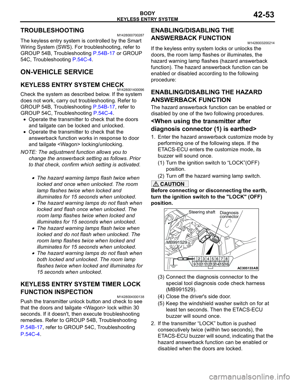
(3) Connect the diagnosis connector to the
special tool diagnosis code check harness
(MB991529).
(4) Close the driver's side door.
(5) Keep the windshield washer switch on for at
least ten seconds. Then the ETACS-ECU
buzzer will sound once.
2. If the transmitter “LOCK” button is pushed
consecutively twice (within two seconds), the
ETACS-ECU buzzer will sound, indicating that the
hazard answerback function can be enabled or
disabled when the doors are locked.
AC305133AB
Diagnosis
connector
MB991529Steering shaft
Page 332 of 788
KEYLESS ENTRY SYSTEM
BODY42-54
•Enable the hazard answerback function
when the doors are locked: The
ETACS-ECU buzzer will sound once.
•Disable the hazard answerback function
when the doors are locked: The
ETACS-ECU buzzer will sound twice.
3. If the transmitter “UNLOCK” button is pushed
consecutively twice (within two seconds), the
ETACS-ECU buzzer will sound, indicating that the
hazard answerback function can be enabled or
disabled when the doors are unlocked.
•Enable the hazard answerback function
when the doors are unlocked: The
ETACS-ECU buzzer will sound once.
•Disable the hazard answerback function
when the doors are unlocked: The
ETACS-ECU buzzer will sound twice.
4. Exit the hazard answerback customize mode by
observing one of the following steps.
(1) Disconnect diagnosis connector terminal (1)
form the earth.
(2) Turn the ignition switch to position other then
“LOCK”(OFF), or remove the ignition key.
(3) Open the driver's side door.
(4) Any other warning buzzer output occurs.
NOTE: If any operation is not done for at least three
minutes after the ETACS-ECU has entered the
customize mode, the hazard answerback customize
mode will be canceled automatically.
connector>
1. Enter the hazard answerback customize mode by
performing one of the following steps. If the
ETACS-ECU enters the customize mode, its
buzzer will sound once.
(1) Turn the ignition switch to “LOCK”(OFF)
position.
(2) Turn off the hazard warning lamp switch.
CAUTION
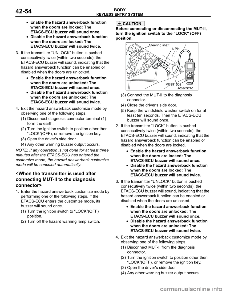
Before connecting or disconnecting the MUT-II,
turn the ignition switch to the "LOCK" (OFF)
position.
(3) Connect the MUT-II to the diagnosis
connector.
(4) Close the driver's side door.
(5) Keep the windshield washer switch on for at
least ten seconds. Then the ETACS-ECU
buzzer will sound once.
2. If the transmitter “LOCK” button is pushed
consecutively twice (within two seconds), the
ETACS-ECU buzzer will sound, indicating that the
hazard answerback function can be enabled or
disabled when the doors are locked.
•Enable the hazard answerback function
when the doors are locked: The
ETACS-ECU buzzer will sound once.
•Disable the hazard answerback function
when the doors are locked: The
ETACS-ECU buzzer will sound twice.
3. If the transmitter “UNLOCK” button is pushed
consecutively twice (within two seconds), the
ETACS-ECU buzzer will sound, indicating that the
hazard answerback function can be enabled or
disabled when the doors are unlocked.
•Enable the hazard answerback function
when the doors are unlocked: The
ETACS-ECU buzzer will sound once.
•Disable the hazard answerback function
when the doors are unlocked: The
ETACS-ECU buzzer will sound twice.
4. Exit the hazard answerback customize mode by
observing one of the following steps.
(1) Disconnect MUT-II from the diagnosis
connector.
(2) Turn the ignition switch to position other then
“LOCK”(OFF), or remove the ignition key.
(3) Open the driver's side door.
(4) Any other warning buzzer output occurs.
AC304777
Steering shaft
ACMB991502
16-Pin
Page 333 of 788
KEYLESS ENTRY SYSTEM
BODY42-55
NOTE: If any operation is not done for at least three
minutes after the ETACS-ECU has entered the
customize mode, the hazard answerback customize
mode will be canceled automatically.
(MB991824) to the diagnosis connector>
1. Enter the hazard answerback customize mode by
performing one of the following steps. If the
ETACS-ECU enters the customize mode, its
buzzer will sound once.
(1) Turn the ignition switch to “LOCK”(OFF)
position.
(2) Turn off the hazard warning lamp switch.
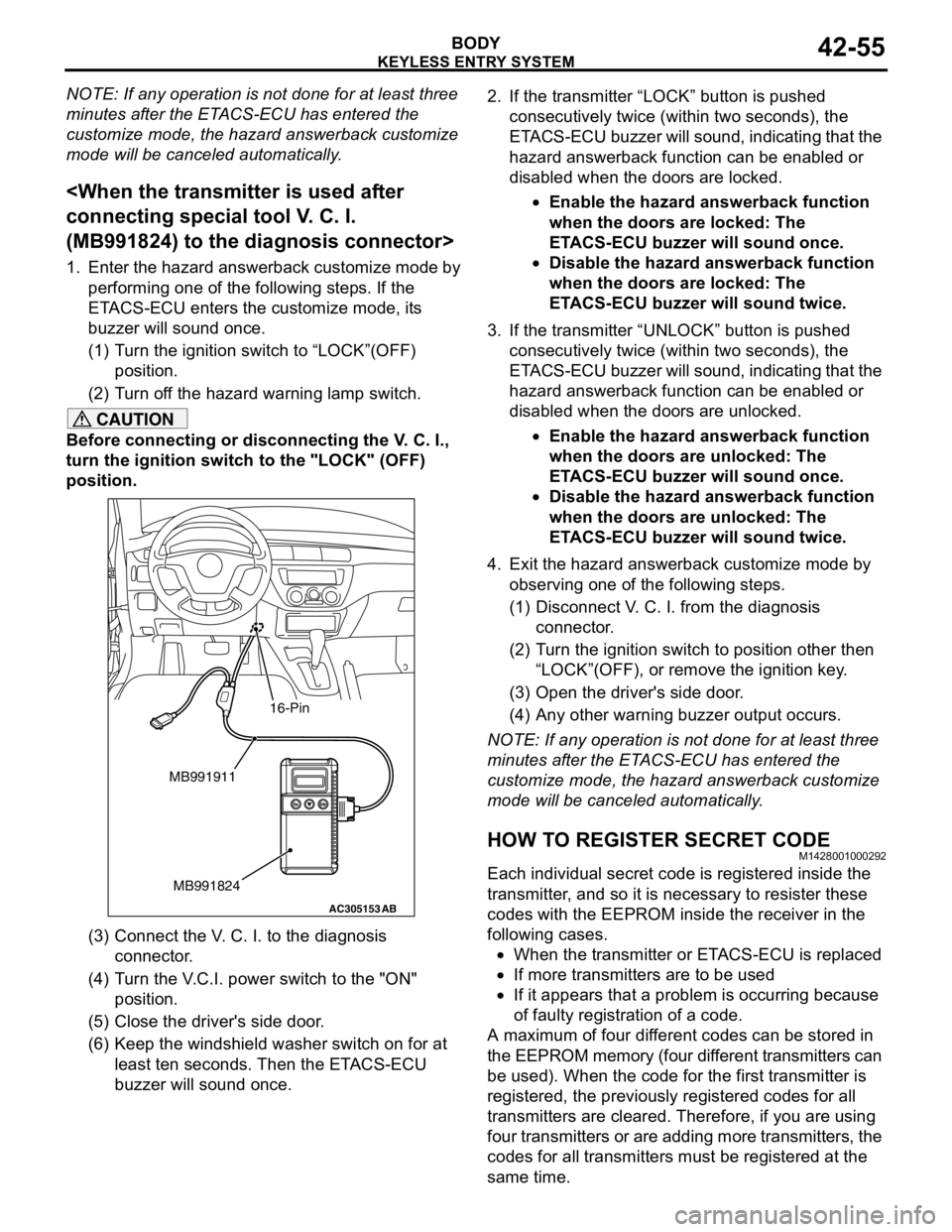
CAUTION
Before connecting or disconnecting the V. C. I.,
turn the ignition switch to the "LOCK" (OFF)
position.
(3) Connect the V. C. I. to the diagnosis
connector.
(4) Turn the V.C.I. power switch to the "ON"
position.
(5) Close the driver's side door.
(6) Keep the windshield washer switch on for at
least ten seconds. Then the ETACS-ECU
buzzer will sound once.2. If the transmitter “LOCK” button is pushed
consecutively twice (within two seconds), the
ETACS-ECU buzzer will sound, indicating that the
hazard answerback function can be enabled or
disabled when the doors are locked.
•Enable the hazard answerback function
when the doors are locked: The
ETACS-ECU buzzer will sound once.
•Disable the hazard answerback function
when the doors are locked: The
ETACS-ECU buzzer will sound twice.
3. If the transmitter “UNLOCK” button is pushed
consecutively twice (within two seconds), the
ETACS-ECU buzzer will sound, indicating that the
hazard answerback function can be enabled or
disabled when the doors are unlocked.
•Enable the hazard answerback function
when the doors are unlocked: The
ETACS-ECU buzzer will sound once.
•Disable the hazard answerback function
when the doors are unlocked: The
ETACS-ECU buzzer will sound twice.
4. Exit the hazard answerback customize mode by
observing one of the following steps.
(1) Disconnect V. C. I. from the diagnosis
connector.
(2) Turn the ignition switch to position other then
“LOCK”(OFF), or remove the ignition key.
(3) Open the driver's side door.
(4) Any other warning buzzer output occurs.
NOTE: If any operation is not done for at least three
minutes after the ETACS-ECU has entered the
customize mode, the hazard answerback customize
mode will be canceled automatically.
HOW TO REGISTER SECRET CODEM1428001000292
Each individual secret code is registered inside the
transmitter, and so it is necessary to resister these
codes with the EEPROM inside the receiver in the
following cases.
•When the transmitter or ETACS-ECU is replaced
•If more transmitters are to be used
•If it appears that a problem is occurring because
of faulty registration of a code.
A maximum of four different codes can be stored in
the EEPROM memory (four different transmitters can
be used). When the code for the first transmitter is
registered, the previously registered codes for all
transmitters are cleared. Therefore, if you are using
four transmitters or are adding more transmitters, the
codes for all transmitters must be registered at the
same time.
AC305153AB
MB991911
MB991824
16-Pin
Page 359 of 788

WINDSHIELD WIPER AND WASHER
EXTERIOR51-21
WINDSHIELD WIPER AND WASHER
GENERAL INFORMATIONM1511000100514
WINDSHIELD WIPER AND WASHER
OPERATION
Windshield Low-speed (and High-speed)
Wiper Operation
•If the windshield low-speed wiper switch is turned
to the ON position with the ignition switch at the
"ACC" or "ON" position, the column switch sends
a low-speed wiper ON and high-speed wiper OFF
signals to the front-ECU. This turns the wiper
signal on and the wiper speed control relay off
(low-speed), causing the wipers to operate at
low-speed.
•If the windshield high-speed wiper switch is
turned to the ON position, the column switch
sends a low-speed wiper OFF and high-speed
wiper ON signals to the front-ECU. This turns
both the wiper signal and the wiper speed control
relay on (high-speed), causing the wipers to
operate at high-speed.
NOTE: The windshield wiper speed is switchable
with the built-in wiper speed control relay.
High-speed operations take place when the wiper
speed control relay is set to "ON" and low-speed
operations take place when the wiper speed control
relay is set to "OFF".
Windshield Intermittent Wiper Operation
The ETACS-ECU calculates the wiper operation
interval according to the voltage signal sent from the
column switch. Then the ETACS-ECU sends a signal
to the front-ECU. The front-ECU determines the
wiper operation interval and turns on the wiper relay
signal relay. This causes the wiper auto stop relay to
turn on. Then the wiper auto stop relay will turn off
after the wipers reach the park position. This causes
the wiper signal relay and then the wipers to turn off.
If the wiper signal relay remains off for the wiper
operation interval, the relay turns on again, causing
the wipers to operate in intermittent mode.
Windshield Mist Wiper Operation
•If the windshield mist wiper switch is turned to the
ON position with the ignition switch at the "ACC"
or "ON" position, the mist wiper high-speed
operation signal is sent to the front-ECU. This
signal turns on the wiper speed control relay,
causing the wipers to work at high-speed while
the mist switch is on.
•While the windshield mist wiper switch remains
turned on when the intermittent mode is still
working, the wipers work as the mist wiper.
However, the wipers return to the intermittent
mode again when the switch is changed back to
"INT" position.
•To prevent the windshield mist wiper from
operating when the windshield wiper switch is
turned OFF, the windshield mist wiper does not
work for 0.5 second after the windshield
intermittent wiper switch, the windshield
low-speed wiper switch and the windshield
high-speed wiper switch are turned OFF.
Windshield Washer Operation
•If the windshield washer switch is turned to ON
position with the ignition switch at "ACC" or "ON"
position, the windshield washer ON signal is sent
to the front-ECU. After 0.3 second, the windshield
wiper signal turns on. After the windshield washer
switch signal turns off, the windshield wiper signal
turns off in three seconds.
•If the windshield washer switch is turned on while
the windshield wiper is at intermittent mode,
when the windshield washer switch is turned OFF
within 0.2 second, the wiper works only once to
perform mist operation by the windshield washer
switch. When the ON condition of the windshield
washer switch continues more than 0.2 second,
the wiper performs the same movement as
normal condition from the time when 0.2 second
has elapsed and then returns to the intermittent
motion.
Page 360 of 788

WINDSHIELD WIPER AND WASHER
EXTERIOR51-22
SERVICE SPECIFICATIONM1511000300325
TROUBLESHOOTINGM1511000700323
The windshield wiper and washer are controlled by
the Smart Wiring System (SWS). For
troubleshooting, refer to GROUP 54B,
Troubleshooting P.54B-17 or GROUP 54C,
Troubleshooting P.54C-4.
NOTE: Even when the ETACS-ECU has failed, the
windshield wiper can work at low speed as fail-safe
mode. (Normally, the windshield wiper operates
when the ignition switch is at the "ACC" position. But,
if it enters the fail-safe mode, the wiper can operate
only when the ignition switch is at the "ON" position.)
ON-VEHICLE SERVICEM1511000800461
WINDSHIELD INTERMITTENT WIPER
INSPECTION
1. If the windshield intermittent wiper interval
adjusting knob is operated, the wiper interval
should change.
2. Holding the windshield intermittent wiper interval
adjusting knob, input the simulated vehicle speed
with MUT-II MB991502 and check that the wiper
interval changes as the vehicle speed changes.
3. If not, carry out the troubleshooting (Refer to
GROUP 54B, Troubleshooting P.54B-17 or
GROUP 54C, Troubleshooting P.54C-4). ItemStandard value
Windshield wiper blade park position mm 34 ± 5
Page 366 of 788

REAR WIPER AND WASHER
EXTERIOR51-28
REAR WIPER AND WASHER
GENERAL INFORMATIONM1511000100525
REAR WIPER AND WASHER OPERATION
Rear Wiper Operation
•If the rear wiper and washer switch is turned to
"INT" position with the ignition switch at "ACC" or
"ON" position, the ETACS-ECU turns ON the rear
wiper drive signal for three seconds
(approximately two cycles), then 7.4 seconds
later the intermittent motion operates every eight
seconds. If the selector lever is moved to the "R"
position when the rear wiper and washer switch is
turned to the "INT" position and the ignition
switch is at the "ACC" or "ON" position, the inhibitor switch "R" turns ON. One second later,
the ETACS-ECU turns ON the rear wiper drive
signal for three seconds (approximately two
cycles). Then, 7.4 seconds later, the intermittent
motion of eight seconds' cycle is restored.
Rear Washer Operation
•If the rear wiper and washer switch is turned to
the ON (washer) position with the ignition switch
at the "ACC" or "ON" position, the rear washer
ON signal is sent to the ETACS-ECU, causing the
rear wiper signal to turn on after 0.3 second. After
the rear washer switch signal turns off, the rear
wiper signal turns off in three seconds. If the rear
washer switch is turned to the ON position while
the rear wiper is in intermittent mode, the rear
washer works for that period when the washer
switch remains on. Then the rear wipers return to
the intermittent mode.
SERVICE SPECIFICATIONM1511000300336
TROUBLESHOOTINGM1511000700334
The rear wiper and washer are controlled by the
Smart Wiring System (SWS). For troubleshooting,
refer to GROUP 54B, Troubleshooting P.54B-17 or
GROUP 54C, Troubleshooting P.54C-4.
ON-VEHICLE SERVICEM1511000800472
CHECK OF REAR WIPER OPERATION
WHEN SELECTOR LEVER IS AT THE "R"
POSITION
1. When the selector lever is moved to the "R"
position with the rear wiper switch at the "INT"
position, the wiper should operate twice or three
times at low speed after approximately one
second.
2. If not, carry out the troubleshooting (Refer to
GROUP 54B, Troubleshooting P.54B-17 or
GROUP 54C, Troubleshooting P.54C-4). ItemStandard value
Rear wiper blade park position mm 42 ± 5
Page 374 of 788
DOOR MIRROR
EXTERIOR51-36
DOOR MIRROR
GENERAL INFORMATIONM1511000100536
DOOR MIRROR OPERATION
Remote Controlled Mirror Operation
•The mirror on the door mirror moves up/down
and left/right by operating the remote controlled
door mirror switch when the ignition switch is in
the "ON" or "ACC" position.Heated Door Mirror operation
•The defogger relay switch is activated (ON) by
turning on the A/C-ECU built-in defogger switch
when the ignition switch is in the "ON" position.
When the defogger relay is turned ON, power is
supplied to the defogger and door mirror, and the
heater of the door mirror (heated door mirror)
starts operations. The defogger comes with a
timer function and will automatically turn OFF the
switch approximately 11 minutes after the
defogger switch is turned ON. The heated door
mirror operations are also terminated along with
the defogger, at this time.
SERVICE SPECIFICATIONM1511000300347
SPECIAL TOOLM1511000601103
TROUBLESHOOTING
DIAGNOSIS TROUBLESHOOTING FLOWM1511014600169
Refer to GROUP 00 − How to Use
Troubleshooting/Inspection Service Points P.00-5.
TROUBLE SYMPTOM CHARTM1511015000160
ItemStandard value
Heated door mirror operation current Ω5.9 − 7.8
Tool Number Name Application
MB990784 Ornament remover Removal of remote controlled
mirror switch
MB990784
Symptom Inspection
procedureReference
page
All heated door mirrors do not operate 1
P.51-37
The right or left heated door mirror does not operate 2
P.51-39