ECU MITSUBISHI LANCER 2005 Repair Manual
[x] Cancel search | Manufacturer: MITSUBISHI, Model Year: 2005, Model line: LANCER, Model: MITSUBISHI LANCER 2005Pages: 788, PDF Size: 45.98 MB
Page 405 of 788
IGNITION SWITCH
CHASSIS ELECTRICAL54A-17
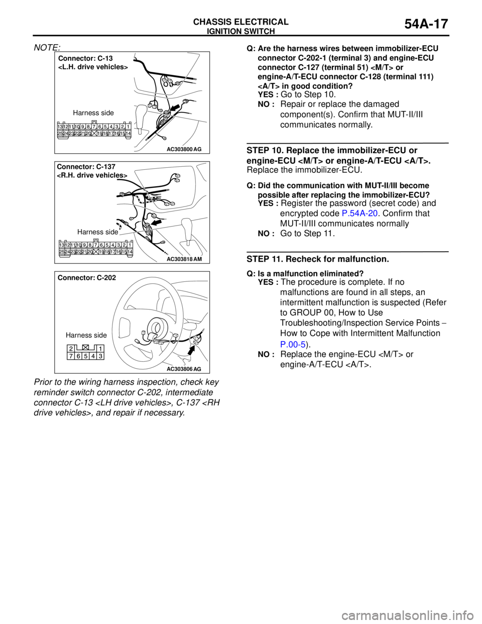
NOTE:
Prior to the wiring harness inspection, check key
reminder switch connector C-202, intermediate
connector C-13
connector C-202-1 (terminal 3) and engine-ECU
connector C-127 (terminal 51)
engine-A/T-ECU connector C-128 (terminal 111)
in good condition?
YES :
Go to Step 10.
NO : Repair or replace the damaged
component(s). Confirm that MUT-II/III
communicates normally.
STEP 10. Replace the immobilizer-ECU or
engine-ECU
Replace the immobilizer-ECU.
Q: Did the communication with MUT-II/III become
possible after replacing the immobilizer-ECU?
YES :
Register the password (secret code) and
encrypted code P.54A-20. Confirm that
MUT-II/III communicates normally
NO : Go to Step 11.
STEP 11. Recheck for malfunction.
Q: Is a malfunction eliminated?
YES :
The procedure is complete. If no
malfunctions are found in all steps, an
intermittent malfunction is suspected (Refer
to GROUP 00, How to Use
Troubleshooting/Inspection Service Points −
How to Cope with Intermittent Malfunction
P.00-5).
NO : Replace the engine-ECU
engine-A/T-ECU .
AC303800
Connector: C-13
Harness side
AG
AC303818
AM
Connector: C-137
Harness side
AC303806
Connector: C-202
Harness side
AG
Page 406 of 788

IGNITION SWITCH
CHASSIS ELECTRICAL54A-18
INSPECTION PROCEDURE 2: The Ignition Key cannot be Registered.
TECHNICAL DESCRIPTION (COMMENT)
The ignition key transponder or the immobilizer-ECU
is suspected to be defective.
TROUBLESHOOTING HINTS
•Malfunction of the ignition key
•Malfunction of immobilizer-ECU
DIAGNOSIS PROCEDURE
STEP 1. MUT-II/III diagnosis code.
Q: Does diagnosis code No.11 reset?
YES :
Refer to P.54A-9.
NO : Replace the ignition key that cannot be
registered. Then re-register the encrypted
code. (Refer to P.54A-20). Verify that the
ignition key can be registered, then Go to
Step 2.
STEP 2. Retest the system.
Q: Does registered ignition key function properly?
YES :
The procedure is complete. (If no
malfunctions are found in all steps, an
intermittent malfunction is suspected. Refer
to GROUP 00, How to Use
Troubleshooting/Inspection Service Points −
How to Cope with Intermittent Malfunction
P.00-5).
NO : Replace the immobilizer-ECU.
INSPECTION PROCEDURE 3: Engine does not Start (Cranking but no Initial Combustion).
TECHNICAL DESCRIPTION (COMMENT)
If the fuel injectors are not operating, there might be
a problem with the MPI system in addition to a
malfunction of the immobilizer system. It is normal for
this to occur if an attempt is made to start the engine
using a key that has not been properly registered.
TROUBLESHOOTING HINTS
•Malfunction of MPI system
•Malfunction of immobilizer-ECU
DIAGNOSIS PROCEDURE
STEP 1. Check the system voltage.
Measure the system voltage during cranking.
Q: Is the voltage 8 volts or more?
YES :
Go to Step 2.
NO : Check the battery. Refer to P.54A-4. The
engine should start.
STEP 2. Check the immobilizer system diagnosis
code and MPI system diagnosis code.
Q: Which diagnosis code resets, the immobilizer
system diagnosis code or the MPI system
diagnosis code?
Immobilizer system diagnosis code is set :
Refer
to P.54A-9.
MPI system diagnosis code is set : Refer to
GROUP 13A, Diagnosis P.13A-15, GROUP
13B, Diagnosis P.13B-15.
No diagnosis code is set : Go to Step 3.
STEP 3. Check the starting system.
Q: Does the engine start?
YES :
Go to Step 4.
NO : Refer to GROUP 13A, Diagnosis −
Symptom Chart P.13A-215, GROUP 13B,
Diagnosis − Symptom Chart P.13B-189. If
the malfunction is not resolved, replace the
immobilizer-ECU. Then register the
password (secret code) and encrypted
code. (Refer to P.54A-20.) The engine
should start.
Page 407 of 788
IGNITION SWITCH
CHASSIS ELECTRICAL54A-19
STEP 4. Retest the system
Q: Is the malfunction eliminated?
YES :
The procedure is complete. If no
malfunction are not found in all steps, an
intermittent malfunction is suspected (Refer
to GROUP 00, How to Use
Troubleshooting/Inspection Service
Points-How to Cope with Intermittent
Malfunction P.00-5).
NO : Replace the immobilizer-ECU.
DATA LIST REFERENCE TABLEM1543007300314
CHECK IMMOBILIZER-ECUM1543007600489
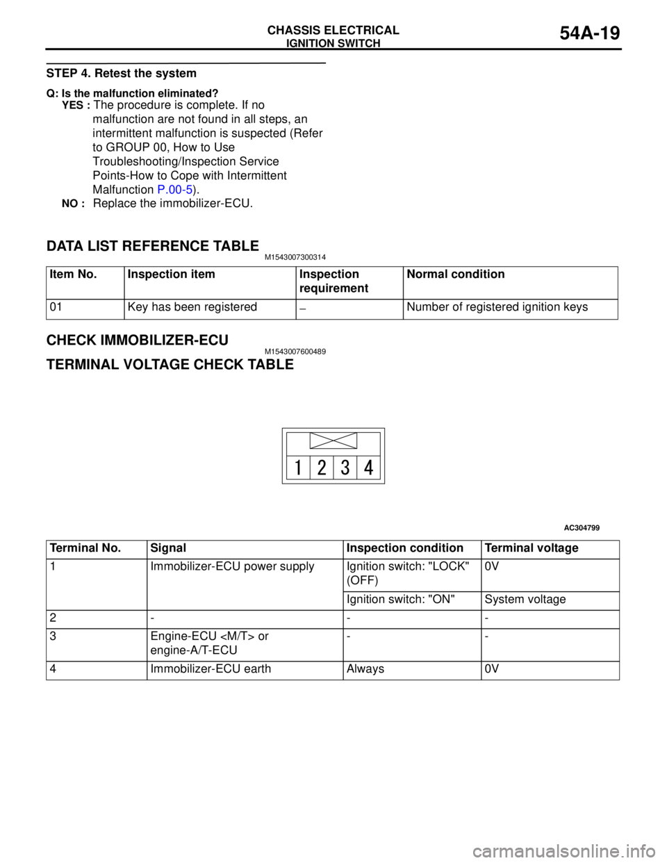
TERMINAL VOLTAGE CHECK TABLE
Item No. Inspection item Inspection
requirementNormal condition
01 Key has been registered
−Number of registered ignition keys
AC304799
Terminal No. Signal Inspection condition Terminal voltage
1 Immobilizer-ECU power supply Ignition switch: "LOCK"
(OFF) 0V
Ignition switch: "ON" System voltage
2- - -
3 Engine-ECU
engine-A/T-ECU--
4 Immobilizer-ECU earth Always 0V
Page 408 of 788

IGNITION SWITCH
CHASSIS ELECTRICAL54A-20
ON-VEHICLE SERVICE
HOW TO REGISTER ENCRYPTED CODEM1543008100410
CAUTION
Because registering the encrypted codes is done
after all previously-registered codes have been
erased, you should keep all of the ignition keys
that have already been registered accessible.
If the ignition key, Immobilizer-ECU,
engine-ECU
replaced or an ignition key is added, encrypted
codes of all the ignition keys must be registered. (A
maximum of eight different ignition key can be
registered.) Moreover, when the immobilizer-ECU
has been replaced, you will need to use MUT-II/III to
register the immobilizer-ECU and input the vehicle
secret code and to register the password (secret
code) that the owner specifies into the
immobilizer-ECU.
If an attempt is made to start the engine with an
unregistered ignition key, cranking occurs, but fuel
supply is cut off to disable the engine. In
approximately.
NOTE: Engine-ECU
has an encrypted code for immobilizer-ECU, and the
encrypted code is registered in the immobilizer-ECU
and ignition key.
POINTS TO NOTE DURING OPERATION
If none of the functions can be used, check the
diagnosis codes, and after carrying out any
necessary repairs, repeat the operation.
If an incorrect password is input ten times in a row,
the immobilizer-ECU judges that an unauthorized
operation is being attempted. Start-prevention mode
will be set, and engine operation will stop and all
special functions will be disabled. If the ignition
switch is turned to "ON" position, "Unauthorized
operation, start- prevention mode" will be cancelled.
KEY ID (ENCRYPTED CODE)
REGISTRATION
All ignition keys can be registered with MUT-II.
Additional ignition keys can be registered with
MUT-II.
Registration with the MUT-II
CAUTION
To prevent damage to MUT-II, always turn the
ignition switch to "LOCK" (OFF) position before
connecting or disconnecting MUT-II.
NOTE: .
•Using the key ID register function will cause all
key IDs that have been previously registered in
the immobilizer-ECU to be erased. All keys need
to be registered. Those which have been
registered before should be on hand before using
this function.
•If registering more than one key, do not
disconnect MUT-II halfway through the
registration process.
•After registering key IDs, check that the engine
can be started using all of the keys that have
been registered. If the engine will not start, refer
to Immobilizer System Diagnosis P.54A-6.
1. Connect MUT-II to diagnosis connector (16- pin).
2. Turn the ignition switch to "ON" position.
3. At "System Select," press "YES"
AC304777
Steering shaft
AB
MB991502
AC000522AD
Page 409 of 788
IGNITION SWITCH
CHASSIS ELECTRICAL54A-21
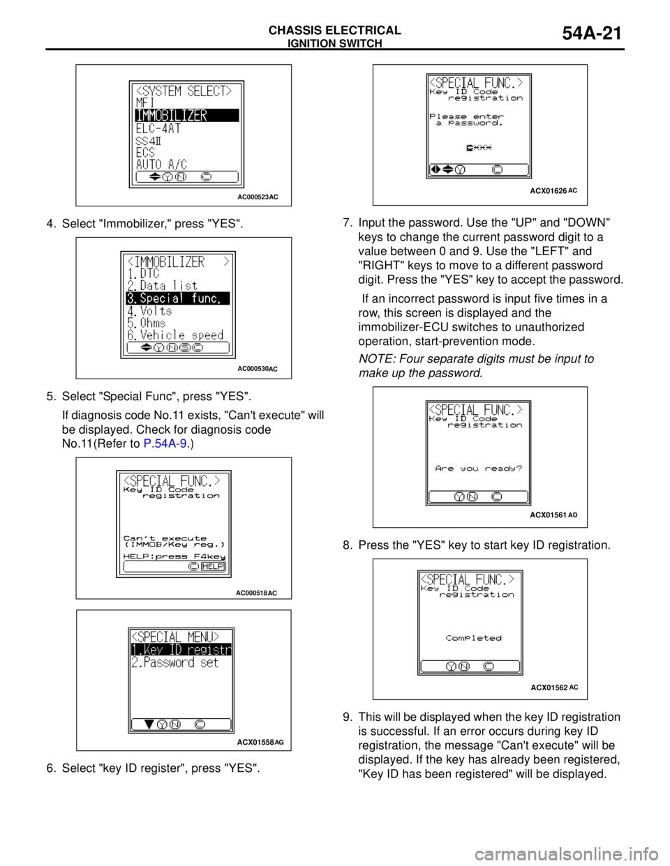
4. Select "Immobilizer," press "YES".
5. Select "Special Func", press "YES".
If diagnosis code No.11 exists, "Can't execute" will
be displayed. Check for diagnosis code
No.11(Refer to P.54A-9.)
6. Select "key ID register", press "YES".7. Input the password. Use the "UP" and "DOWN"
keys to change the current password digit to a
value between 0 and 9. Use the "LEFT" and
"RIGHT" keys to move to a different password
digit. Press the "YES" key to accept the password.
If an incorrect password is input five times in a
row, this screen is displayed and the
immobilizer-ECU switches to unauthorized
operation, start-prevention mode.
NOTE: Four separate digits must be input to
make up the password.
8. Press the "YES" key to start key ID registration.
9. This will be displayed when the key ID registration
is successful. If an error occurs during key ID
registration, the message "Can't execute" will be
displayed. If the key has already been registered,
"Key ID has been registered" will be displayed.
AC000523AC
AC000530AC
AC000518AC
ACX01558AG
ACX01626AC
ACX01561AD
ACX01562AC
Page 410 of 788
IGNITION SWITCH
CHASSIS ELECTRICAL54A-22
10.The number of keys currently registered will be
displayed. To register an additional key, replace
the ignition key with the next key to be registered
within five seconds and then press the "YES" key.
Key ID registration screen will be displayed, then
register another key.
If key ID registration is complete, press the "NO"
key.
NOTE: A maximum of eight different keys can be
registered.
11.This completes the registration operation. Turn
the ignition switch "LOCK" (OFF) and leave it off
for approximately ten seconds.
12.Check that the engine can be started with each of
the ignition keys.
13.Check that the immobilizer system diagnosis
code and MPI system diagnosis code did not set.
14.Turn the ignition switch to "LOCK" (OFF) position.
15.Disconnect MUT-II.
Registration of additional keys with the
MUT-II
Additional key(s) can be registered with the MUT-II
while keeping all existing key data.
CAUTION
To prevent damage to MUT-II, always turn the
ignition switch to "LOCK" (OFF) position before
connecting or disconnecting MUT-II.
NOTE: To register additional keys with the MUT-II,
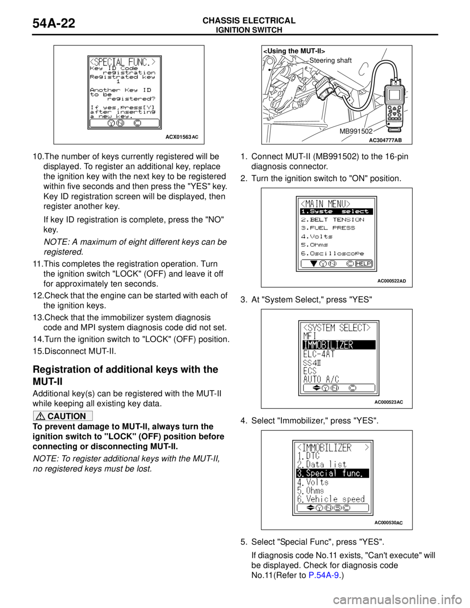
no registered keys must be lost.1. Connect MUT-II (MB991502) to the 16-pin
diagnosis connector.
2. Turn the ignition switch to "ON" position.
3. At "System Select," press "YES"
4. Select "Immobilizer," press "YES".
5. Select "Special Func", press "YES".
If diagnosis code No.11 exists, "Can't execute" will
be displayed. Check for diagnosis code
No.11(Refer to P.54A-9.)
ACX01563ACAC304777
Steering shaft
AB
MB991502
AC000522AD
AC000523AC
AC000530AC
Page 411 of 788
IGNITION SWITCH
CHASSIS ELECTRICAL54A-23
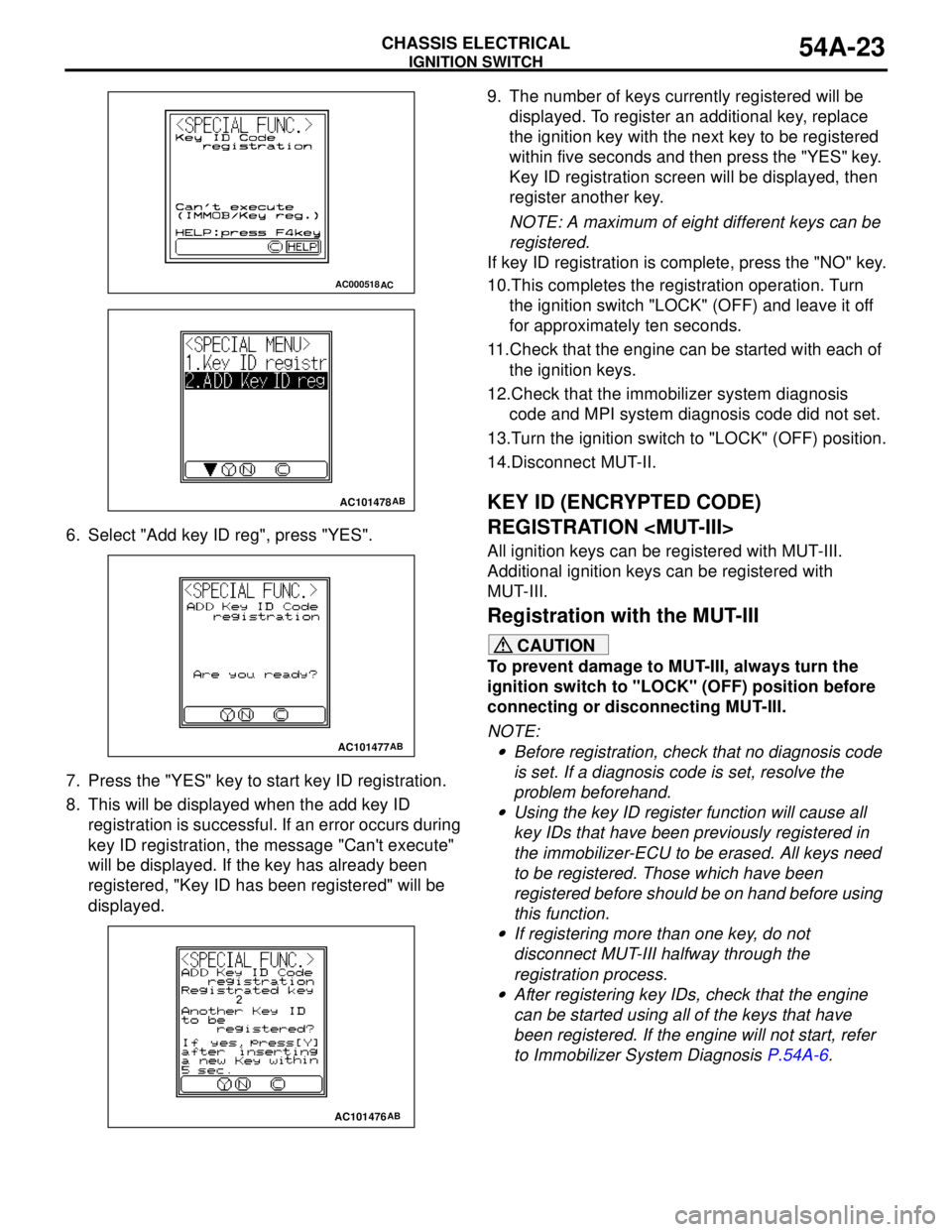
6. Select "Add key ID reg", press "YES".
7. Press the "YES" key to start key ID registration.
8. This will be displayed when the add key ID
registration is successful. If an error occurs during
key ID registration, the message "Can't execute"
will be displayed. If the key has already been
registered, "Key ID has been registered" will be
displayed.9. The number of keys currently registered will be
displayed. To register an additional key, replace
the ignition key with the next key to be registered
within five seconds and then press the "YES" key.
Key ID registration screen will be displayed, then
register another key.
NOTE: A maximum of eight different keys can be
registered.
If key ID registration is complete, press the "NO" key.
10.This completes the registration operation. Turn
the ignition switch "LOCK" (OFF) and leave it off
for approximately ten seconds.
11.Check that the engine can be started with each of
the ignition keys.
12.Check that the immobilizer system diagnosis
code and MPI system diagnosis code did not set.
13.Turn the ignition switch to "LOCK" (OFF) position.
14.Disconnect MUT-II.
KEY ID (ENCRYPTED CODE)
REGISTRATION
All ignition keys can be registered with MUT-III.
Additional ignition keys can be registered with
MUT-III.
Registration with the MUT-III
CAUTION
To prevent damage to MUT-III, always turn the
ignition switch to "LOCK" (OFF) position before
connecting or disconnecting MUT-III.
NOTE: .
•Before registration, check that no diagnosis code
is set. If a diagnosis code is set, resolve the
problem beforehand.
•Using the key ID register function will cause all
key IDs that have been previously registered in
the immobilizer-ECU to be erased. All keys need
to be registered. Those which have been
registered before should be on hand before using
this function.
•If registering more than one key, do not
disconnect MUT-III halfway through the
registration process.
•After registering key IDs, check that the engine
can be started using all of the keys that have
been registered. If the engine will not start, refer
to Immobilizer System Diagnosis P.54A-6.
AC000518AC
AC101478AB
AC101477AB
AC101476AB
Page 412 of 788
IGNITION SWITCH
CHASSIS ELECTRICAL54A-24
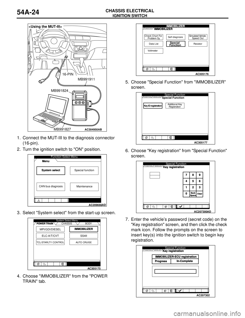
1. Connect the MUT-III to the diagnosis connector
(16-pin).
2. Turn the ignition switch to "ON" position.
3. Select "System select" from the start-up screen.
4. Choose "IMMOBILIZER" from the "POWER
TRAIN" tab.5. Choose "Special Function" from "IMMOBILIZER"
screen.
6. Choose "Key registration" from "Special Function"
screen.
7. Enter the vehicle’s password (secret code) on the
"Key registration" screen, and then click the check
mark icon. Follow the prompts on the screen to
insert key(s) into the ignition switch to begin key
registration.
AC304950
MB991911
16-PIN
MB991827 MB991824
AB
System selectSpecial function
CAN bus diagnosis
Function Select Menu
Menu
AC209666
Maintenance
AD
MPI/GDI/DIESEL
ELC-A/T/CVT
IMMOBILIZER
SS4II
TCL/STARLTY CONTROLAUTO CRUISE CHASSIS BODY System Select Menu
POWER TRAIN
AC305175
Check Chart For
Problem Sy
Data ListSpecial
Function
Self-diagnosisSimulated Vehicle
Speed Out
Resistor
Voltmeter
POWERTRAINIMMOBILIZERIMMOBILIZER
AC305176
Key ID registrationAdditional Key
Registration
POWERTRAINSpecial FunctionIMMOBILIZERSpecial Function
AC305177
POWERTRAIN IMMOBILIZERSpecial Function
789
456
123
0
BackBackSpaceSpaceClearClear
Key registration
AC207300
AD
POWERTRAIN IMMOBILIZERSpecial Function
IMMOBILIZER-ECU registration
ProgressIn-CompleteKey registration
AC207302
Page 414 of 788
IGNITION SWITCH
CHASSIS ELECTRICAL54A-26
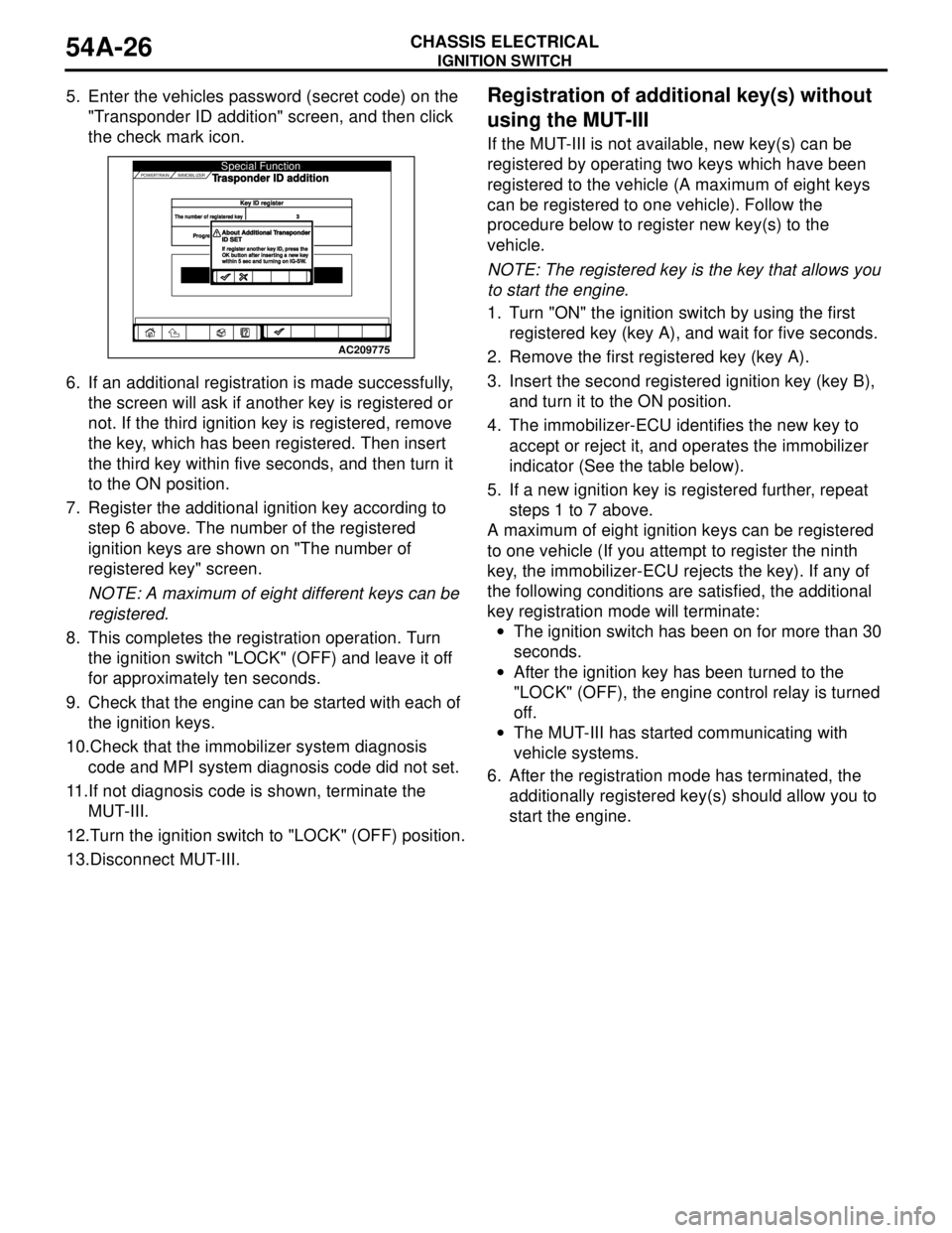
5. Enter the vehicles password (secret code) on the
"Transponder ID addition" screen, and then click
the check mark icon.
6. If an additional registration is made successfully,
the screen will ask if another key is registered or
not. If the third ignition key is registered, remove
the key, which has been registered. Then insert
the third key within five seconds, and then turn it
to the ON position.
7. Register the additional ignition key according to
step 6 above. The number of the registered
ignition keys are shown on "The number of
registered key" screen.
NOTE: A maximum of eight different keys can be
registered.
8. This completes the registration operation. Turn
the ignition switch "LOCK" (OFF) and leave it off
for approximately ten seconds.
9. Check that the engine can be started with each of
the ignition keys.
10.Check that the immobilizer system diagnosis
code and MPI system diagnosis code did not set.
11.If not diagnosis code is shown, terminate the
MUT-III.
12.Turn the ignition switch to "LOCK" (OFF) position.
13.Disconnect MUT-III.Registration of additional key(s) without
using the MUT-III
If the MUT-III is not available, new key(s) can be
registered by operating two keys which have been
registered to the vehicle (A maximum of eight keys
can be registered to one vehicle). Follow the
procedure below to register new key(s) to the
vehicle.
NOTE: The registered key is the key that allows you
to start the engine.
1. Turn "ON" the ignition switch by using the first
registered key (key A), and wait for five seconds.
2. Remove the first registered key (key A).
3. Insert the second registered ignition key (key B),
and turn it to the ON position.
4. The immobilizer-ECU identifies the new key to
accept or reject it, and operates the immobilizer
indicator (See the table below).
5. If a new ignition key is registered further, repeat
steps 1 to 7 above.
A maximum of eight ignition keys can be registered
to one vehicle (If you attempt to register the ninth
key, the immobilizer-ECU rejects the key). If any of
the following conditions are satisfied, the additional
key registration mode will terminate:
•The ignition switch has been on for more than 30
seconds.
•After the ignition key has been turned to the
"LOCK" (OFF), the engine control relay is turned
off.
•The MUT-III has started communicating with
vehicle systems.
6. After the registration mode has terminated, the
additionally registered key(s) should allow you to
start the engine.
AC207301
AC209775POWERTRAIN IMMOBILIZER
Key ID registerey ID registerThe number of registered keyThe number of registered key3
Progre
Progre
Special FunctionTrasponder ID addition
About Additional TAbout Additional TransponderransponderID SETID SETIf register another key ID, press theIf register another key ID, press theOK button after inserting a new keyOK button after inserting a new keywithin 5 sec and turning on IG-SWwithin 5 sec and turning on IG-SW.
Page 415 of 788
IGNITION SWITCH
CHASSIS ELECTRICAL54A-27
IGNITION SWITCH
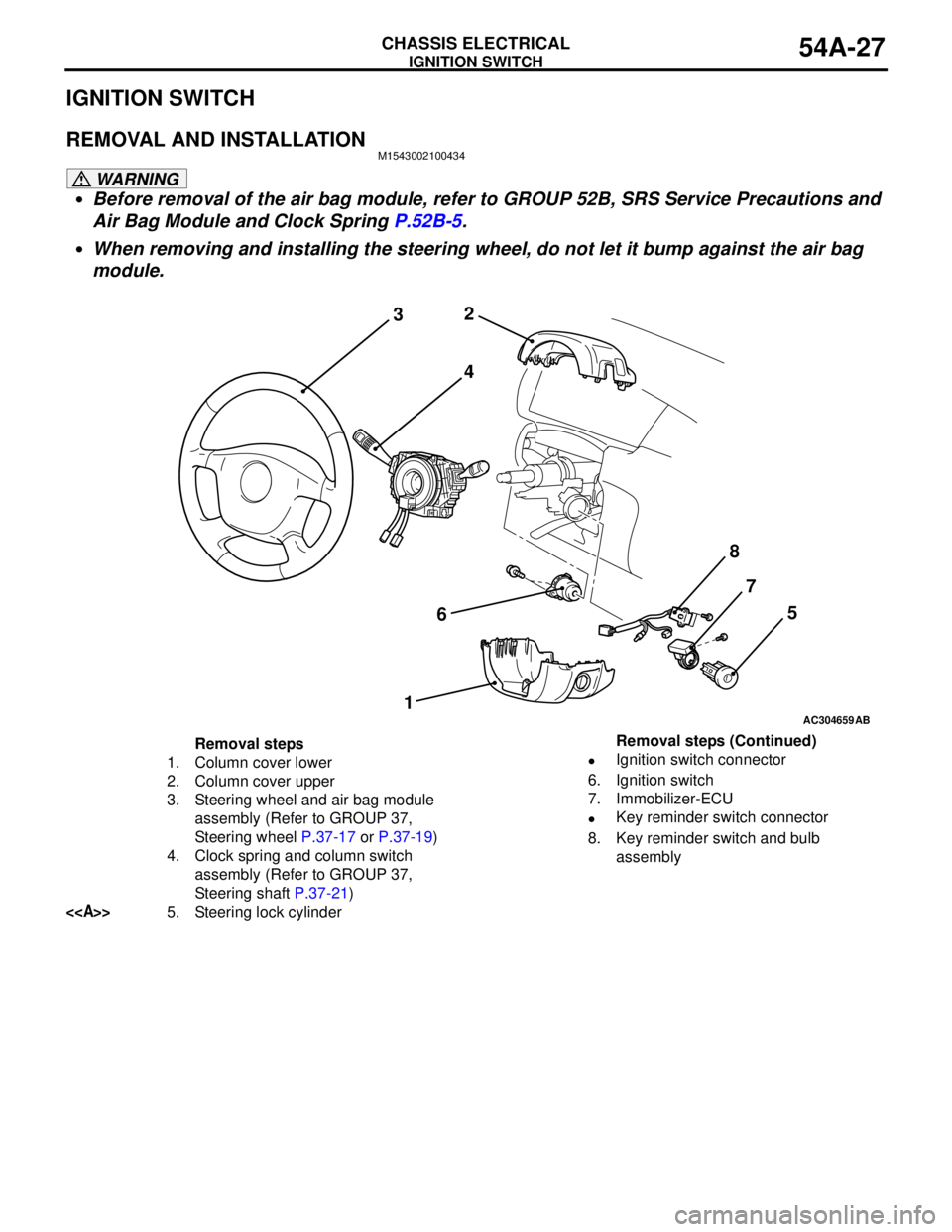
REMOVAL AND INSTALLATIONM1543002100434
WARNING
•Before removal of the air bag module, refer to GROUP 52B, SRS Service Precautions and
Air Bag Module and Clock Spring P.52B-5.
•When removing and installing the steering wheel, do not let it bump against the air bag
module.
AC304659
2
3
4
67
15
AB
8
Removal steps
1. Column cover lower
2. Column cover upper
3. Steering wheel and air bag module
assembly (Refer to GROUP 37,
Steering wheel P.37-17 or P.37-19)
4. Clock spring and column switch
assembly (Refer to GROUP 37,
Steering shaft P.37-21)
<>5. Steering lock cylinder•Ignition switch connector
6. Ignition switch
7. Immobilizer-ECU
•Key reminder switch connector
8. Key reminder switch and bulb
assembly Removal steps (Continued)