ECU MITSUBISHI LANCER 2005 Owner's Guide
[x] Cancel search | Manufacturer: MITSUBISHI, Model Year: 2005, Model line: LANCER, Model: MITSUBISHI LANCER 2005Pages: 788, PDF Size: 45.98 MB
Page 174 of 788
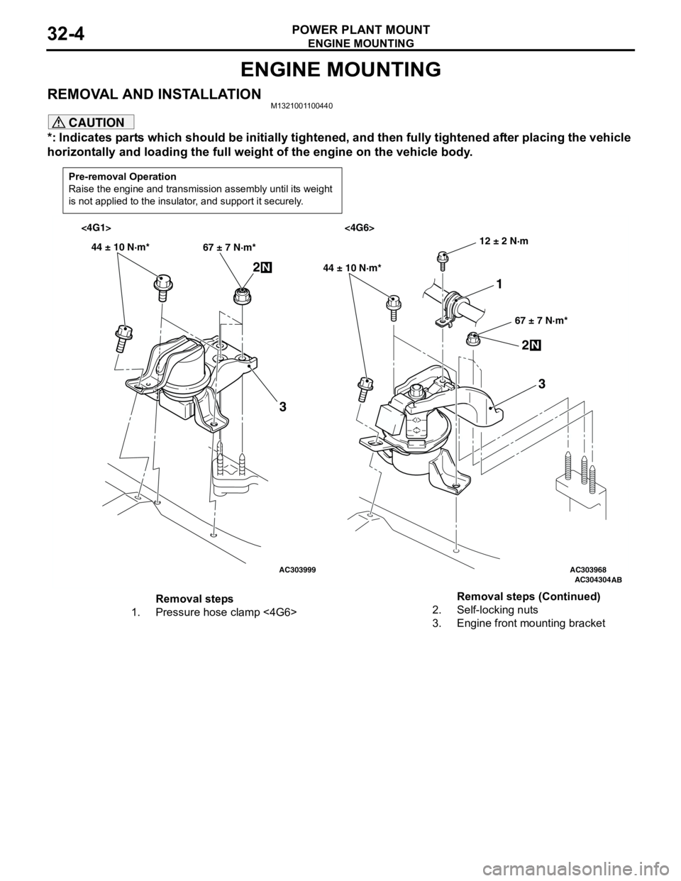
ENGINE MOUNTING
POWER PLANT MOUNT32-4
ENGINE MOUNTING
REMOVAL AND INSTALLATIONM1321001100440
CAUTION
*: Indicates parts which should be initially tightened, and then fully tightened after placing the vehicle
horizontally and loading the full weight of the engine on the vehicle body.
Pre-removal Operation
Raise the engine and transmission assembly until its weight
is not applied to the insulator, and support it securely.
AC303999AC303968AC304304
AB
<4G1> <4G6>
44 ± 10 N·m*
67 ± 7 N·m*
2N
3
44 ± 10 N·m*
67 ± 7 N·m*
2N
3
12 ± 2 N·m
1
Removal steps
1. Pressure hose clamp <4G6>2. Self-locking nuts
3. Engine front mounting bracketRemoval steps (Continued)
Page 175 of 788
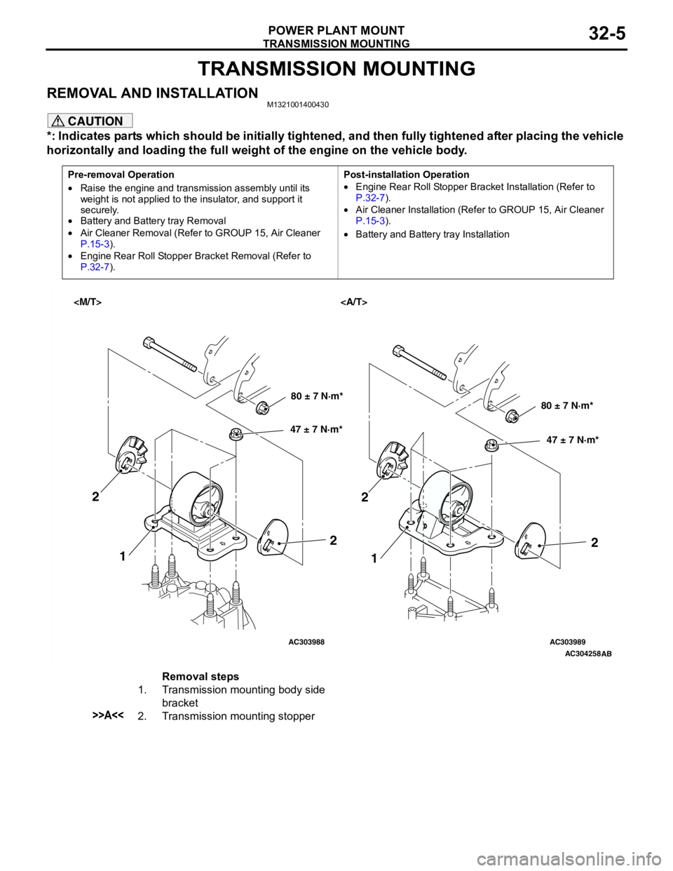
TRANSMISSION MOUNTING
POWER PLANT MOUNT32-5
TRANSMISSION MOUNTING
REMOVAL AND INSTALLATIONM1321001400430
CAUTION
*: Indicates parts which should be initially tightened, and then fully tightened after placing the vehicle
horizontally and loading the full weight of the engine on the vehicle body.
Pre-removal Operation
•Raise the engine and transmission assembly until its
weight is not applied to the insulator, and support it
securely.
•Battery and Battery tray Removal
•Air Cleaner Removal (Refer to GROUP 15, Air Cleaner
P.15-3).
•Engine Rear Roll Stopper Bracket Removal (Refer to
P.32-7).Post-installation Operation
•Engine Rear Roll Stopper Bracket Installation (Refer to
P.32-7).
•Air Cleaner Installation (Refer to GROUP 15, Air Cleaner
P.15-3).
•Battery and Battery tray Installation
AC303988AC303989
AC304258
AB
80 ± 7 N·m*
47 ± 7 N·m*80 ± 7 N·m*
47 ± 7 N·m*
1
1 2
22
2
Removal steps
1. Transmission mounting body side
bracket
>>A<<2. Transmission mounting stopper
Page 191 of 788
Page 218 of 788
Page 222 of 788
STABILIZER BAR
REAR SUSPENSION34-22
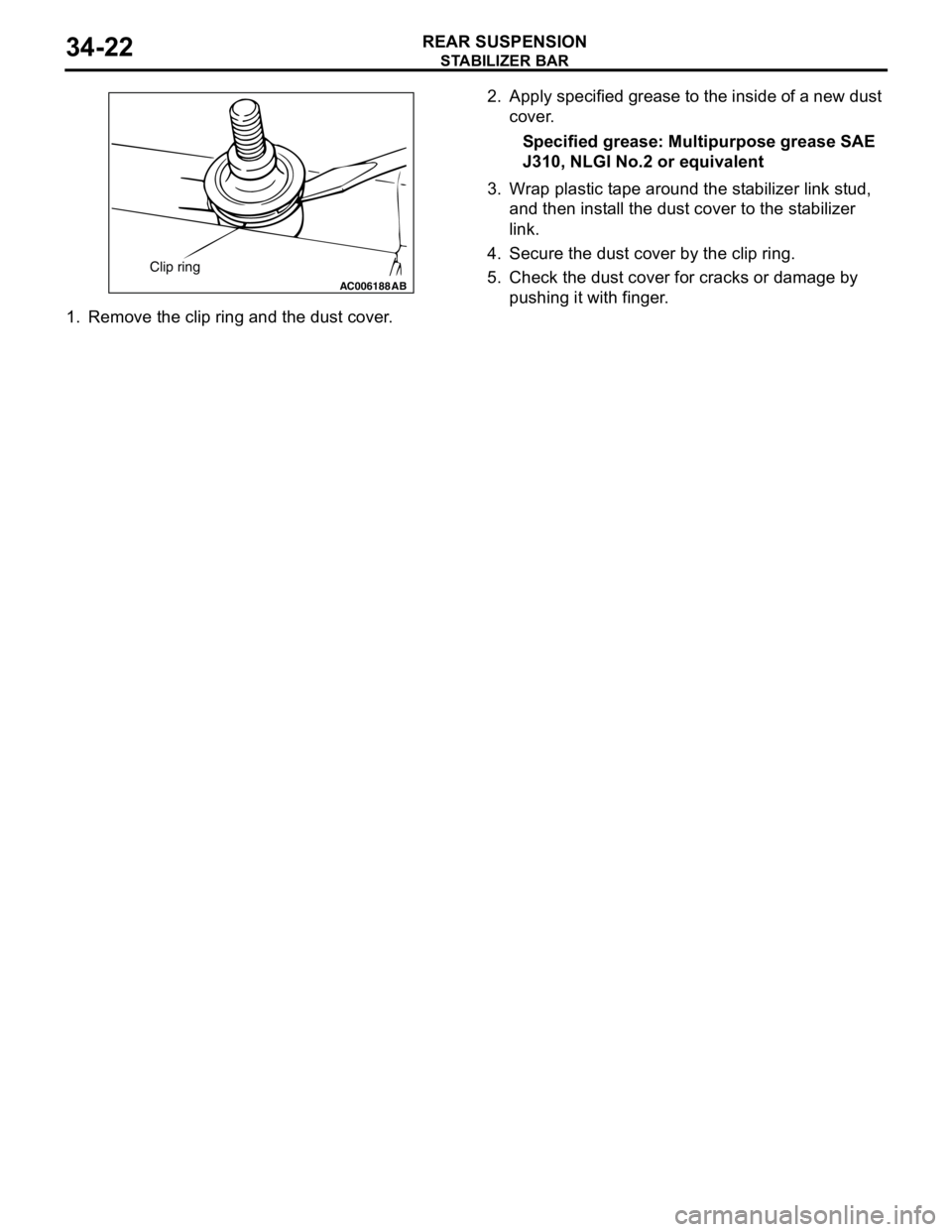
1. Remove the clip ring and the dust cover.2. Apply specified grease to the inside of a new dust
cover.
Specified grease: Multipurpose grease SAE
J310, NLGI No.2 or equivalent
3. Wrap plastic tape around the stabilizer link stud,
and then install the dust cover to the stabilizer
link.
4. Secure the dust cover by the clip ring.
5. Check the dust cover for cracks or damage by
pushing it with finger.
AC006188 AB
Clip ring
Page 227 of 788
LUBRICANTS
PARKING BRAKES36-3
LUBRICANTS
M1361000400293
ON-VEHICLE SERVICE
PARKING BRAKE LEVER STROKE
CHECK AND ADJUSTMENT
M1361000900339
1. Pull the parking brake lever with a force of
approximately 200 N and count the number of
notches.
Standard value: 5 − 7 notches
2. If the parking brake lever stroke is not the
standard value, adjust as described below.
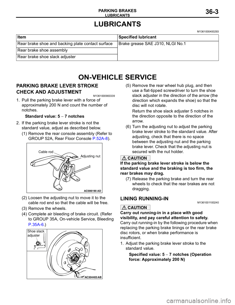
(1) Remove the rear console assembly (Refer to
GROUP 52A, Rear Floor Console P.52A-8).
(2) Loosen the adjusting nut to move it to the
cable rod end so that the cable will be free.
(3) Remove the wheels.
(4) Complete air bleeding of brake circuit. (Refer
to GROUP 35A, On-vehicle Service, Bleeding
P.35A-6.)(5) Remove the rear wheel hub plug, and then
use a flat-tipped screwdriver to turn the shoe
slack adjuster in the direction of the arrow (the
direction which expands the shoe) so that the
disc will not rotate.
Return the shoe slack adjuster 5 notches in
the direction opposite to the direction of the
arrow.
(6) Turn the adjusting nut to adjust the parking
brake lever stroke to the standard value. After
adjusting, check that there is no space
between the adjusting nut and the parking
brake lever. Check that the adjusting nut is
secured with the nut holder.
CAUTION
If the parking brake lever stroke is below the
standard value and the braking is too firm, the
rear brakes may drag.
(7) Release the parking brake and turn the rear
wheels to check that the rear brakes are not
dragging.
LINING RUNNING-INM1361001100240
CAUTION
Carry out running-in in a place with good
visibility, and pay careful attention to safety.
Carry out running-in by the following procedure when
replacing the parking brake linings or the rear brake
disc rotors, or when brake performance is
insufficient.
1. Adjust the parking brake lever stroke to the
standard value.
Specified value: 5 − 7 notches (Operation
force: Approximately 200 N) Item Specified lubricant
Rear brake shoe and backing plate contact surface Brake grease SAE J310, NLGI No.1
Rear brake shoe assembly
Rear brake shoe slack adjuster
AC006190
Cable rod
Adjusting nut
AD
AC304403AB
Shoe slack
adjuster
Page 247 of 788
ON-VEHICLE SERVICE
POWER STEERING37-13
STEERING WHEEL RETURN TO CENTRE
CHECK
M1372001800317
Conduct a road test:
1. Make both gradual and sudden turns and check
the steering wheel return.
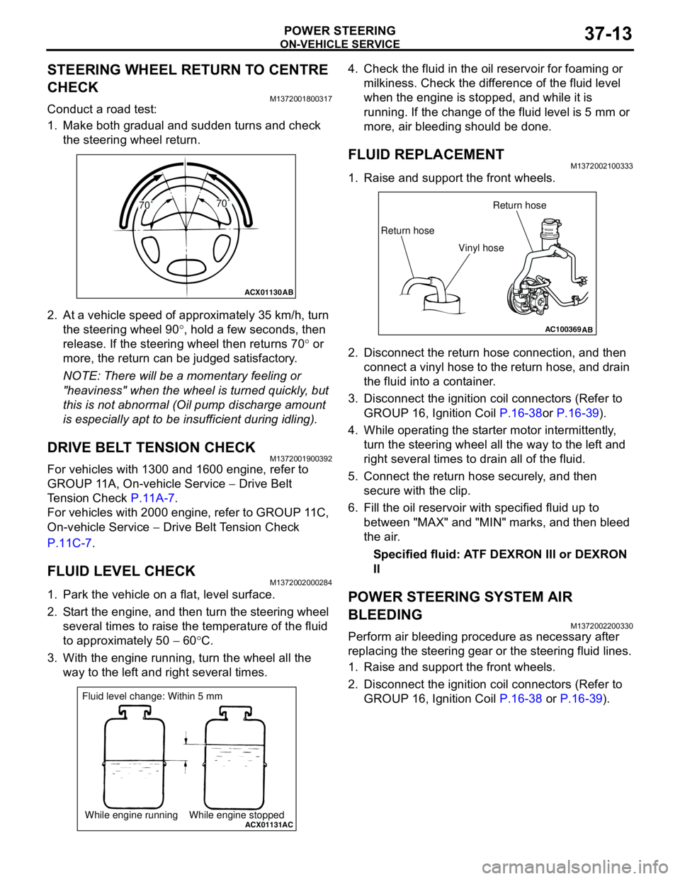
2. At a vehicle speed of approximately 35 km/h, turn
the steering wheel 90°, hold a few seconds, then
release. If the steering wheel then returns 70° or
more, the return can be judged satisfactory.
NOTE: There will be a momentary feeling or
"heaviness" when the wheel is turned quickly, but
this is not abnormal (Oil pump discharge amount
is especially apt to be insufficient during idling).
DRIVE BELT TENSION CHECKM1372001900392
For vehicles with 1300 and 1600 engine, refer to
GROUP 11A, On-vehicle Service − Drive Belt
Tension Check P.11A-7.
For vehicles with 2000 engine, refer to GROUP 11C,
On-vehicle Service − Drive Belt Tension Check
P.11C-7.
FLUID LEVEL CHECKM1372002000284
1. Park the vehicle on a flat, level surface.
2. Start the engine, and then turn the steering wheel
several times to raise the temperature of the fluid
to approximately 50 − 60°C.
3. With the engine running, turn the wheel all the
way to the left and right several times.4. Check the fluid in the oil reservoir for foaming or
milkiness. Check the difference of the fluid level
when the engine is stopped, and while it is
running. If the change of the fluid level is 5 mm or
more, air bleeding should be done.
FLUID REPLACEMENTM1372002100333
1. Raise and support the front wheels.
2. Disconnect the return hose connection, and then
connect a vinyl hose to the return hose, and drain
the fluid into a container.
3. Disconnect the ignition coil connectors (Refer to
GROUP 16, Ignition Coil P.16-38or P.16-39).
4. While operating the starter motor intermittently,
turn the steering wheel all the way to the left and
right several times to drain all of the fluid.
5. Connect the return hose securely, and then
secure with the clip.
6. Fill the oil reservoir with specified fluid up to
between "MAX" and "MIN" marks, and then bleed
the air.
Specified fluid: ATF DEXRON III or DEXRON
II
POWER STEERING SYSTEM AIR
BLEEDING
M1372002200330
Perform air bleeding procedure as necessary after
replacing the steering gear or the steering fluid lines.
1. Raise and support the front wheels.
2. Disconnect the ignition coil connectors (Refer to
GROUP 16, Ignition Coil P.16-38 or P.16-39).
ACX01130
AB
70˚70˚
ACX01131While engine running While engine stoppedAC
Fluid level change: Within 5 mm
AC100369AB
Return hoseReturn hose
Vinyl hose
Page 260 of 788
POWER STEERING GEAR BOX AND LINKAGE
POWER STEERING37-26
INSTALLATION SERVICE POINT
>>A<< JOINT COVER GROMMET
INSTALLATION
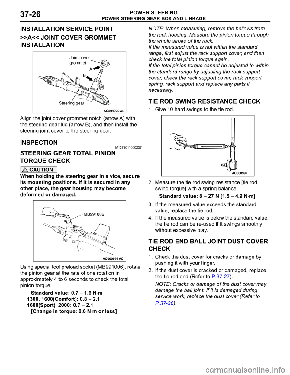
Align the joint cover grommet notch (arrow A) with
the steering gear lug (arrow B), and then install the
steering joint cover to the steering gear.
INSPECTIONM1372011000237
STEERING GEAR TOTAL PINION
TORQUE CHECK
CAUTION
When holding the steering gear in a vice, secure
its mounting positions. If it is secured in any
other place, the gear housing may become
deformed or damaged.
Using special tool preload socket (MB991006), rotate
the pinion gear at the rate of one rotation in
approximately 4 to 6 seconds to check the total
pinion torque.
Standard value: 0.7 − 1.6 N⋅m
1300, 1600(Comfort): 0.8 − 2.1
1600(Sport), 2000: 0.7 − 2.1
[Change in torque: 0.6 N⋅m or less]NOTE: When measuring, remove the bellows from
the rack housing. Measure the pinion torque through
the whole stroke of the rack.
If the measured value is not within the standard
range, first adjust the rack support cover, and then
check the total pinion torque again.
If the total pinion torque cannot be adjusted to within
the standard range by adjusting the rack support
cover, check the rack support cover, rack support
spring, rack support and replace any parts if
necessary.
TIE ROD SWING RESISTANCE CHECK
1. Give 10 hard swings to the tie rod.
2. Measure the tie rod swing resistance [tie rod
swing torque] with a spring balance.
Standard value: 8 − 27 N [1.5 − 4.9 N⋅m]
3. If the measured value exceeds the standard
value, replace the tie rod.
4. If the measured value is below the standard value,
the tie rod can be re-used if it swings smoothly
without excessive play.
TIE ROD END BALL JOINT DUST COVER
CHECK
1. Check the dust cover for cracks or damage by
pushing it with your finger.
2. If the dust cover is cracked or damaged, replace
the tie rod end (Refer to P.37-27).
NOTE: Cracks or damage of the dust cover may
damage the ball joint. If it is damaged during
service work, replace the dust cover (Refer to
P.37-36).
AC304922AB
A
B Joint cover
grommet
Steering gear
AC000996 AC
MB991006
AC000997
Page 268 of 788
POWER STEERING GEAR BOX AND LINKAGE
POWER STEERING37-34
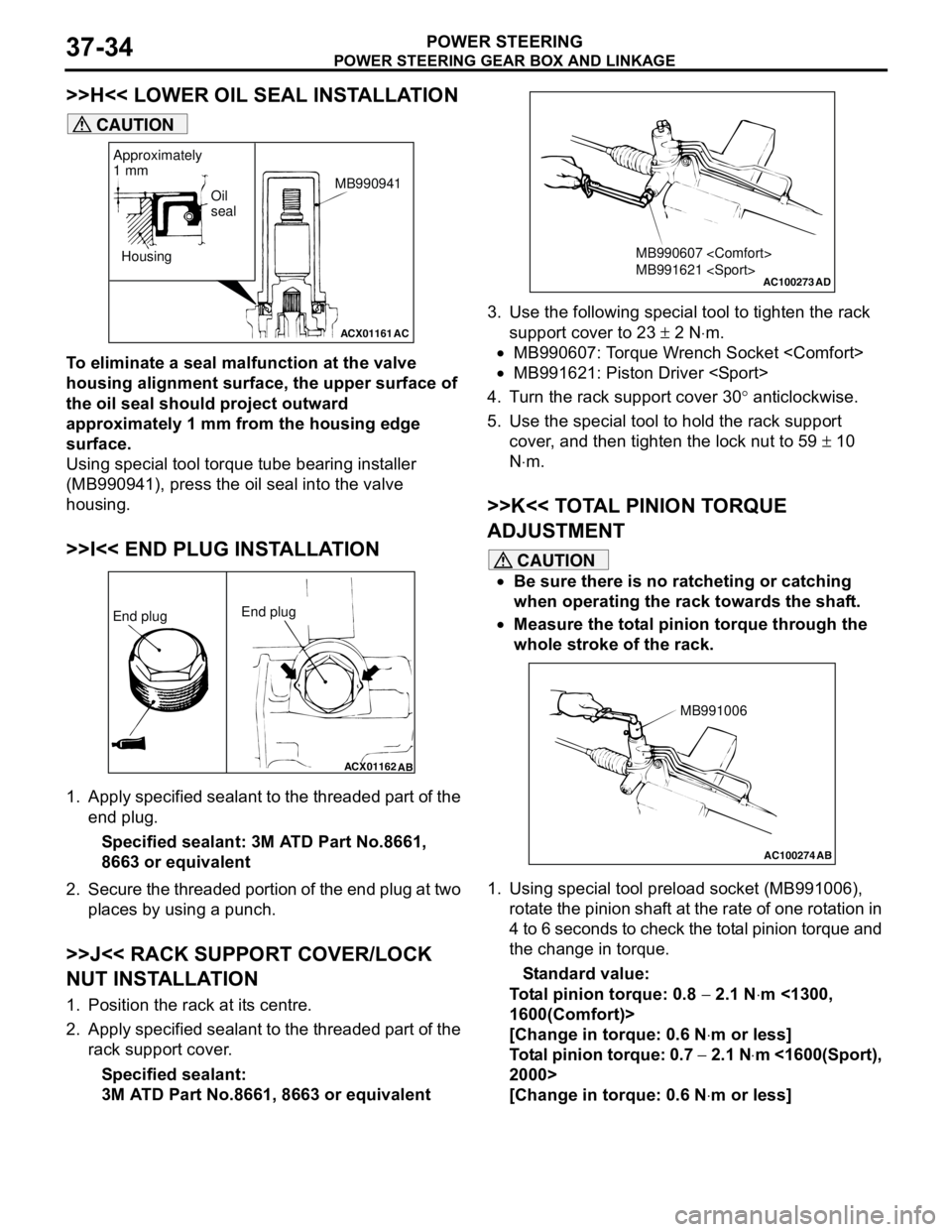
>>H<< LOWER OIL SEAL INSTALLATION
CAUTION
To eliminate a seal malfunction at the valve
housing alignment surface, the upper surface of
the oil seal should project outward
approximately 1 mm from the housing edge
surface.
Using special tool torque tube bearing installer
(MB990941), press the oil seal into the valve
housing.
>>I<< END PLUG INSTALLATION
1. Apply specified sealant to the threaded part of the
end plug.
Specified sealant: 3M ATD Part No.8661,
8663 or equivalent
2. Secure the threaded portion of the end plug at two
places by using a punch.
>>J<< RACK SUPPORT COVER/LOCK
NUT INSTALLATION
1. Position the rack at its centre.
2. Apply specified sealant to the threaded part of the
rack support cover.
Specified sealant:
3M ATD Part No.8661, 8663 or equivalent3. Use the following special tool to tighten the rack
support cover to 23 ± 2 N⋅m.
•MB990607: Torque Wrench Socket
•MB991621: Piston Driver
4. Turn the rack support cover 30° anticlockwise.
5. Use the special tool to hold the rack support
cover, and then tighten the lock nut to 59 ± 10
N⋅m.
>>K<< TOTAL PINION TORQUE
ADJUSTMENT
CAUTION
•Be sure there is no ratcheting or catching
when operating the rack towards the shaft.
•Measure the total pinion torque through the
whole stroke of the rack.
1. Using special tool preload socket (MB991006),
rotate the pinion shaft at the rate of one rotation in
4 to 6 seconds to check the total pinion torque and
the change in torque.
Standard value:
Total pinion torque: 0.8 − 2.1 N⋅m <1300,
1600(Comfort)>
[Change in torque: 0.6 N⋅m or less]
Total pinion torque: 0.7 − 2.1 N⋅m <1600(Sport),
2000>
[Change in torque: 0.6 N⋅m or less]
ACX01161
Housing
AC
Oil
seal
Approximately
1 mm
MB990941
ACX01162
AB
End plugEnd plug
AC100273
MB990607
MB991621
AD
AC100274 AB
MB991006
Page 269 of 788
POWER STEERING GEAR BOX AND LINKAGE
POWER STEERING37-35
CAUTION
When adjusting, set at the highest value of the
standard value range.
NOTE: If the total pinion toque cannot be adjusted
to the standard value within the specified return
angle, check the rack support cover components
and replace any parts if necessary.
2. If the total pinion torque or the change in torque is
outside the standard value, move the rack support
cover 0 − 30°, and adjust the pinion torque again.
>>L<< TAB WASHER/TIE ROD
INSTALLATION
After installing the tie rod to the rack, fold tab washer
end (two locations) to tie rod notch.
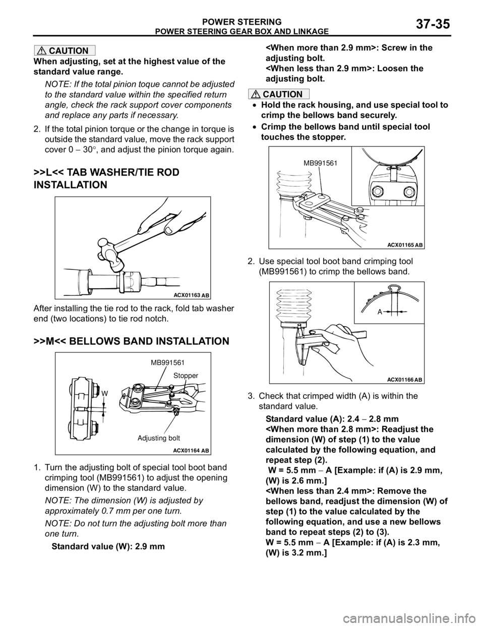
>>M<< BELLOWS BAND INSTALLATION
1. Turn the adjusting bolt of special tool boot band
crimping tool (MB991561) to adjust the opening
dimension (W) to the standard value.
NOTE: The dimension (W) is adjusted by
approximately 0.7 mm per one turn.
NOTE: Do not turn the adjusting bolt more than
one turn.
Standard value (W): 2.9 mm
adjusting bolt.
adjusting bolt.
CAUTION
•Hold the rack housing, and use special tool to
crimp the bellows band securely.
•Crimp the bellows band until special tool
touches the stopper.
2. Use special tool boot band crimping tool
(MB991561) to crimp the bellows band.
3. Check that crimped width (A) is within the
standard value.
Standard value (A): 2.4 − 2.8 mm
dimension (W) of step (1) to the value
calculated by the following equation, and
repeat step (2).
W = 5.5 mm − A [Example: if (A) is 2.9 mm,
(W) is 2.6 mm.]
bellows band, readjust the dimension (W) of
step (1) to the value calculated by the
following equation, and use a new bellows
band to repeat steps (2) to (3).
W = 5.5 mm − A [Example: if (A) is 2.3 mm,
(W) is 3.2 mm.]
ACX01163
AB
ACX01164
AB
WMB991561
Adjusting boltStopper
ACX01165AB
MB991561
ACX01166
AB
A