dış MITSUBISHI LANCER 2005 Service Manual
[x] Cancel search | Manufacturer: MITSUBISHI, Model Year: 2005, Model line: LANCER, Model: MITSUBISHI LANCER 2005Pages: 788, PDF Size: 45.98 MB
Page 124 of 788
EMISSION CONTROL
ENGINE AND EMISSION CONTROL17-16
5. Replace the gasket, and tighten to the specified
torque.
Tightening torque:
<4G1> 21 ± 4 N⋅m
<4G6> 20 ± 2 N⋅m
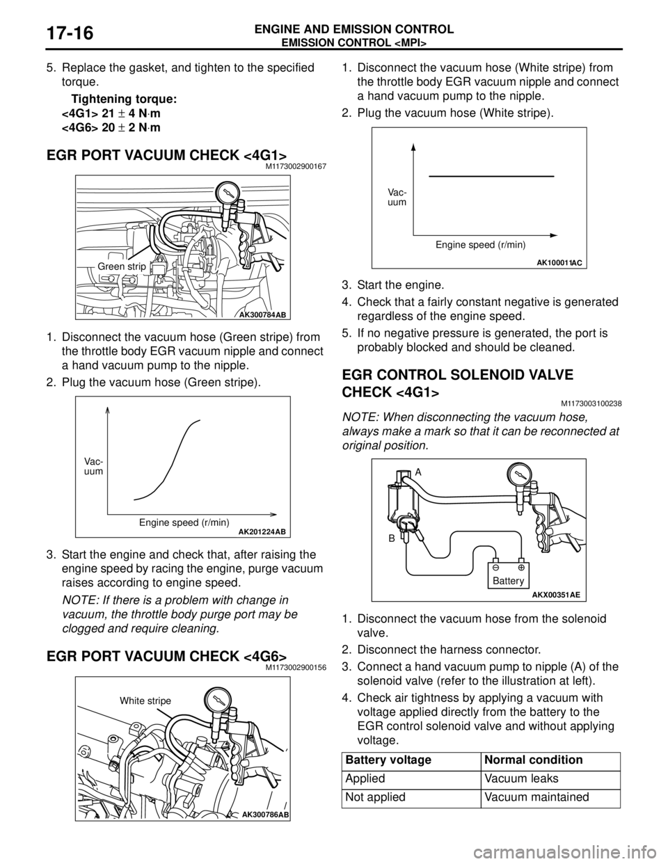
EGR PORT VACUUM CHECK <4G1>M1173002900167
1. Disconnect the vacuum hose (Green stripe) from
the throttle body EGR vacuum nipple and connect
a hand vacuum pump to the nipple.
2. Plug the vacuum hose (Green stripe).
3. Start the engine and check that, after raising the
engine speed by racing the engine, purge vacuum
raises according to engine speed.
NOTE: If there is a problem with change in
vacuum, the throttle body purge port may be
clogged and require cleaning.
EGR PORT VACUUM CHECK <4G6>M1173002900156
1. Disconnect the vacuum hose (White stripe) from
the throttle body EGR vacuum nipple and connect
a hand vacuum pump to the nipple.
2. Plug the vacuum hose (White stripe).
3. Start the engine.
4. Check that a fairly constant negative is generated
regardless of the engine speed.
5. If no negative pressure is generated, the port is
probably blocked and should be cleaned.
EGR CONTROL SOLENOID VALVE
CHECK <4G1>
M1173003100238
NOTE: When disconnecting the vacuum hose,
always make a mark so that it can be reconnected at
original position.
1. Disconnect the vacuum hose from the solenoid
valve.
2. Disconnect the harness connector.
3. Connect a hand vacuum pump to nipple (A) of the
solenoid valve (refer to the illustration at left).
4. Check air tightness by applying a vacuum with
voltage applied directly from the battery to the
EGR control solenoid valve and without applying
voltage.
AK300784AB
Green strip
AK201224AB
Vac-
uum
Engine speed (r/min)
AK300786AB
White stripe
Battery voltage Normal condition
Applied Vacuum leaks
Not applied Vacuum maintained
AK100011AC
Vac-
uum
Engine speed (r/min)
AKX00351
A
B
AE
Battery
Page 125 of 788

EMISSION CONTROL
ENGINE AND EMISSION CONTROL17-17
5. Measure the resistance between the terminals of
the solenoid valve.
Standard value: 29 − 35 Ω (at 20°C)
EGR CONTROL SOLENOID VALVE
CHECK <4G6>
M1173003100249
NOTE: When disconnecting the vacuum hose,
always make a mark so that it can be reconnected at
original position.1. Disconnect the vacuum hose from the solenoid
valve.
2. Disconnect the harness connector.
3. Connect a hand vacuum pump to nipple (A) of the
solenoid valve (refer to the illustration at left).
4. Check air tightness by applying a vacuum with
voltage applied directly from the battery to the
EGR control solenoid valve and without applying
voltage.
5. Measure the resistance between the terminals of
the solenoid valve.
Standard value: 29 − 35 Ω (at 20°C)
AKX00352
AK201251AB
A
B
C
Battery
Battery
voltageB nipple
conditionNormal condition
Not applied Open Vacuum
maintained
Applied Open Vacuum leaks
Closed Vacuum
maintained
AK100016
Page 133 of 788
26-1
GROUP 26
FRONT AXLE
CONTENTS
GENERAL INFORMATION . . . . . . . .26-2
SERVICE SPECIFICATIONS . . . . . . .26-3
LUBRICANTS . . . . . . . . . . . . . . . . . .26-3
SPECIAL TOOLS . . . . . . . . . . . . . . . .26-4
ON-VEHICLE SERVICE . . . . . . . . . . .26-7
WHEEL BEARING AXIAL PLAY CHECK . . 26-7
HUB BOLT REPLACEMENT . . . . . . . . . . . 26-7
FRONT AXLE HUB ASSEMBLY . . . .26-8
REMOVAL AND INSTALLATION . . . . . . . . 26-8
INSPECTION . . . . . . . . . . . . . . . . . . . . . . . . 26-11
DISASSEMBLY AND REASSEMBLY . . . . . 26-11
INSPECTION . . . . . . . . . . . . . . . . . . . . . . . . 26-13
DRIVE SHAFT ASSEMBLY . . . . . . . .26-14
REMOVAL AND INSTALLATION . . . . . . . . 26-14
DISASSEMBLY AND REASSEMBLY . . . . . 26-18
INSPECTION . . . . . . . . . . . . . . . . . . . . . . . . 26-21
BJ BOOT (RESIN BOOT)
REPLACEMENT . . . . . . . . . . . . . . . . . . . . . 26-21
Page 136 of 788
SPECIAL TOOLS
FRONT AXLE26-4
SPECIAL TOOLS
M1261000600375
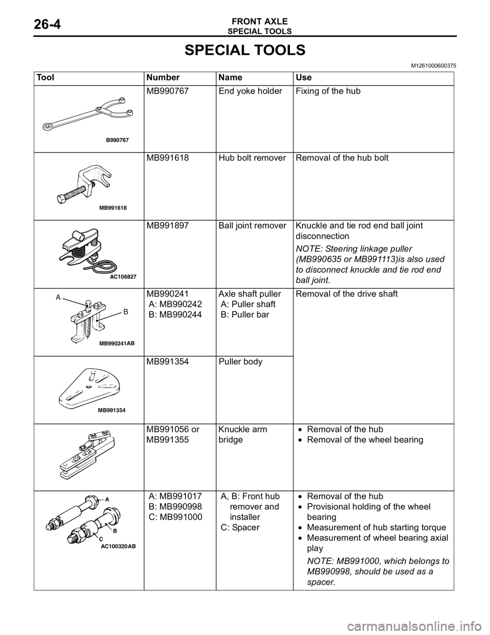
Tool Number Name Use
MB990767 End yoke holder Fixing of the hub
MB991618 Hub bolt remover Removal of the hub bolt
MB991897 Ball joint remover Knuckle and tie rod end ball joint
disconnection
NOTE: Steering linkage puller
(MB990635 or MB991113)is also used
to disconnect knuckle and tie rod end
ball joint.
MB990241
A: MB990242
B: MB990244Axle shaft puller
A: Puller shaft
B: Puller barRemoval of the drive shaft
MB991354 Puller body
MB991056 or
MB991355Knuckle arm
bridge•Removal of the hub
•Removal of the wheel bearing
A: MB991017
B: MB990998
C: MB991000A, B: Front hub
remover and
installer
C: Spacer•Removal of the hub
•Provisional holding of the wheel
bearing
•Measurement of hub starting torque
•Measurement of wheel bearing axial
play
NOTE: MB991000, which belongs to
MB990998, should be used as a
spacer.
B990767
MB991618
AC106827
MB990241AB
A
B
MB991354
AC100320 ABA
B
C
Page 139 of 788
ON-VEHICLE SERVICE
FRONT AXLE26-7
ON-VEHICLE SERVICE
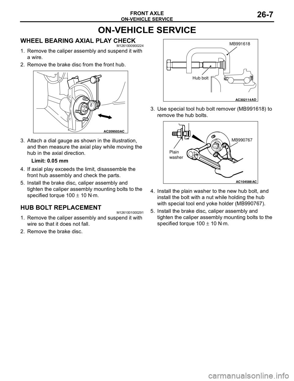
WHEEL BEARING AXIAL PLAY CHECKM1261000900224
1. Remove the caliper assembly and suspend it with
a wire.
2. Remove the brake disc from the front hub.
3. Attach a dial gauge as shown in the illustration,
and then measure the axial play while moving the
hub in the axial direction.
Limit: 0.05 mm
4. If axial play exceeds the limit, disassemble the
front hub assembly and check the parts.
5. Install the brake disc, caliper assembly and
tighten the caliper assembly mounting bolts to the
specified torque 100 ± 10 N⋅m.
HUB BOLT REPLACEMENTM1261001000291
1. Remove the caliper assembly and suspend it with
wire so that it does not fall.
2. Remove the brake disc.3. Use special tool hub bolt remover (MB991618) to
remove the hub bolts.
4. Install the plain washer to the new hub bolt, and
install the bolt with a nut while holding the hub
with special tool end yoke holder (MB990767).
5. Install the brake disc, caliper assembly and
tighten the caliper assembly mounting bolts to the
specified torque 100 ± 10 N⋅m.
AC209503AC
AC302114
MB991618
AD
Hub bolt
AC104588
MB990767
Plain
washer
AC
Page 140 of 788
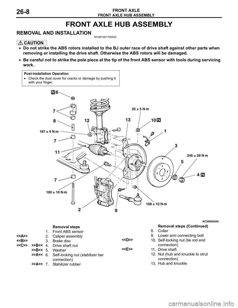
FRONT AXLE HUB ASSEMBLY
FRONT AXLE26-8
FRONT AXLE HUB ASSEMBLY
REMOVAL AND INSTALLATIONM1261001700353
CAUTION
•Do not strike the ABS rotors installed to the BJ outer race of drive shaft against other parts when
removing or installing the drive shaft. Otherwise the ABS rotors will be damaged.
•Be careful not to strike the pole piece at the tip of the front ABS sensor with tools during servicing
work.
Post-installation Operation
•Check the dust cover for cracks or damage by pushing it
with your finger.
AC209505
N
N
N
5
4 3 1 810
9 2 76
167 ± 9 N·m25 ± 5 N·m
108 ± 10 N·m245 ± 29 N·m
100 ± 10 N·m
AC
7
7
111213
Removal steps
1. Front ABS sensor
<>
2. Caliper assembly
<>
3. Brake disc
<
>>B<<5. Washer
>>A<<6. Self-locking nut (stabilizer bar
connection)
>>A<<7. Stabilizer rubber8. Collar
9. Lower arm connecting bolt
<
10. Self-locking nut (tie rod end
connection)
<
11 . D r i v e s h a f t
12. Nut (hub and knuckle to strut
connection)
13. Hub and knuckle
Removal steps (Continued)
Page 141 of 788
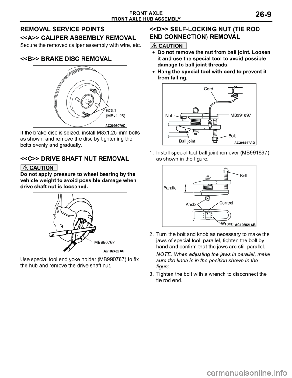
Page 143 of 788
FRONT AXLE HUB ASSEMBLY
FRONT AXLE26-11
INSPECTIONM1261001800242
•Check the hub for cracks and spline for wear.
•Check the knuckle for cracks.
•Check for defective bearing.NOTE: If the meshing of the wheel bearing outer
race and the knuckle, or of the wheel bearing
inner race and the hub, is loose, replace the
bearing or damaged parts.
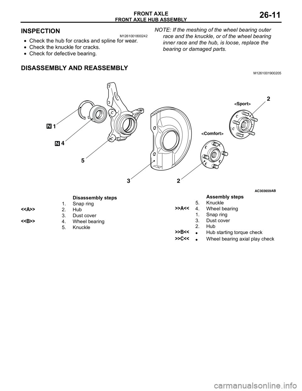
DISASSEMBLY AND REASSEMBLYM1261001900205
AC303659
N
N4 1
5
32
AB
2
Disassembly steps
1. Snap ring
<>2. Hub
3. Dust cover
<>4. Wheel bearing
5. KnuckleAssembly steps
5. Knuckle
>>A<<4. Wheel bearing
1. Snap ring
3. Dust cover
2. Hub
>>B<<•Hub starting torque check
>>C<<•Wheel bearing axial play check
Page 144 of 788
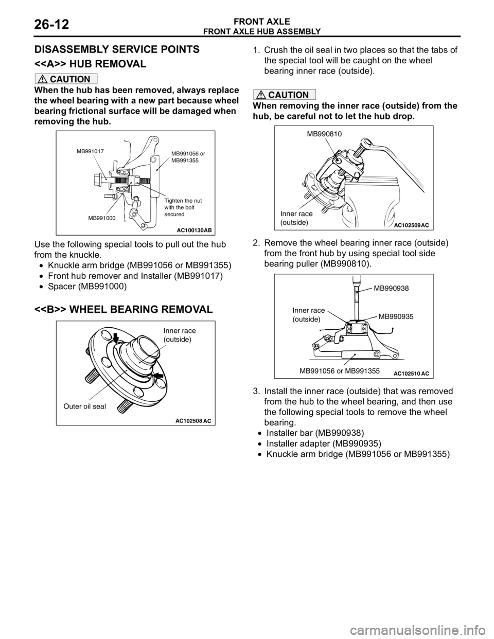
Page 145 of 788
FRONT AXLE HUB ASSEMBLY
FRONT AXLE26-13
REASSEMBLY SERVICE POINTS
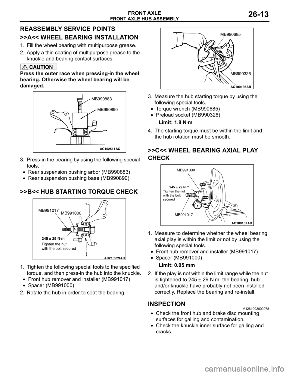
>>A<< WHEEL BEARING INSTALLATION
1. Fill the wheel bearing with multipurpose grease.
2. Apply a thin coating of multipurpose grease to the
knuckle and bearing contact surfaces.
CAUTION
Press the outer race when pressing-in the wheel
bearing. Otherwise the wheel bearing will be
damaged.
3. Press-in the bearing by using the following special
tools.
•Rear suspension bushing arbor (MB990883)
•Rear suspension bushing base (MB990890)
>>B<< HUB STARTING TORQUE CHECK
1. Tighten the following special tools to the specified
torque, and then press-in the hub into the knuckle.
•Front hub remover and installer (MB991017)
•Spacer (MB991000)
2. Rotate the hub in order to seat the bearing.3. Measure the hub starting torque by using the
following special tools.
•Torque wrench (MB990685)
•Preload socket (MB990326)
Limit: 1.8 N⋅m
4. The starting torque must be within the limit and
the hub rotation must be smooth.
>>C<< WHEEL BEARING AXIAL PLAY
CHECK
1. Measure to determine whether the wheel bearing
axial play is within the limit or not by using the
following special tools.
•Front hub remover and installer (MB991017)
•Spacer (MB991000)
Limit: 0.05 mm
2. If the play is not within the limit range while the nut
is tightened to 245 ± 29 N⋅m, the bearing, hub
and/or knuckle have probably not been installed
correctly. Replace the bearing and re-install.
INSPECTIONM1261002000078
•Check the front hub and brake disc mounting
surfaces for galling and contamination.
•Check the knuckle inner surface for galling and
cracks.
AC102511
MB990883
MB990890
AC
AC210929AC
MB991000 MB991017
245 ± 29 N·m
Tighten the nut
with the bolt secured
AC100136
MB990685
MB990326
AB
AC100137
MB991000
MB991017
245 ± 29 N·m
AB Tighten the nut
with the bolt
secured