electrical MITSUBISHI LANCER 2005 Manual PDF
[x] Cancel search | Manufacturer: MITSUBISHI, Model Year: 2005, Model line: LANCER, Model: MITSUBISHI LANCER 2005Pages: 788, PDF Size: 45.98 MB
Page 415 of 788
IGNITION SWITCH
CHASSIS ELECTRICAL54A-27
IGNITION SWITCH
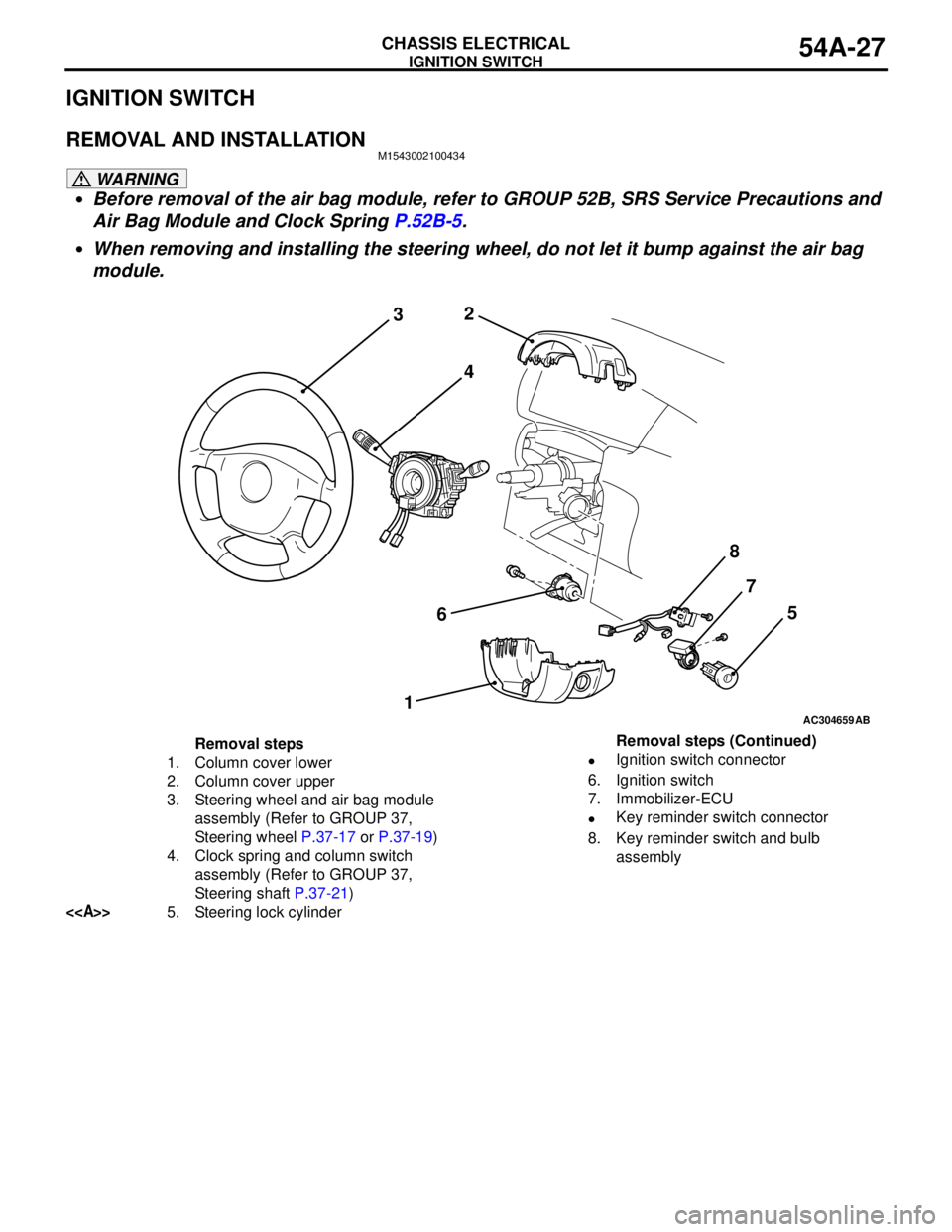
REMOVAL AND INSTALLATIONM1543002100434
WARNING
•Before removal of the air bag module, refer to GROUP 52B, SRS Service Precautions and
Air Bag Module and Clock Spring P.52B-5.
•When removing and installing the steering wheel, do not let it bump against the air bag
module.
AC304659
2
3
4
67
15
AB
8
Removal steps
1. Column cover lower
2. Column cover upper
3. Steering wheel and air bag module
assembly (Refer to GROUP 37,
Steering wheel P.37-17 or P.37-19)
4. Clock spring and column switch
assembly (Refer to GROUP 37,
Steering shaft P.37-21)
<>5. Steering lock cylinder•Ignition switch connector
6. Ignition switch
7. Immobilizer-ECU
•Key reminder switch connector
8. Key reminder switch and bulb
assembly Removal steps (Continued)
Page 416 of 788
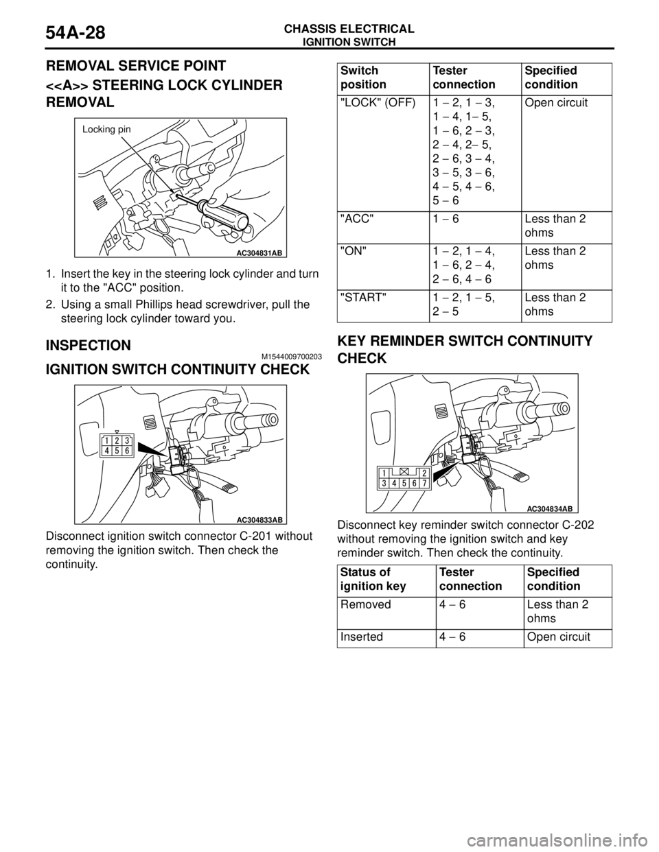
Page 417 of 788

COMBINATION METER ASSEMBLY
CHASSIS ELECTRICAL54A-29
COMBINATION METER ASSEMBLY
SERVICE SPECIFICATIONSM1543000300324
SEALANTM1543024600028
SPECIAL TOOLSM1543000601652
ItemStandard value
Speedometer indication error km/h (mph) 20 (12) 20 − 24 (12 − 15)
40 (25) 40 − 44 (25 − 28)
80 (50) 80 − 85 (50 − 53)
120 (75) 121 − 127 (75 − 79)
160 (100) 162 − 169 (100 − 105)
200 (125) 203 − 211 (126 − 131)
Tachometer indication error r/min 700
± 120
2,000
− 175 + 225
3,000
− 175 + 300
4,000
− 225 + 375
5,000
− 225 + 425
6,000
− 225 + 475
7,000
− 200 + 500
8,000
− 100 + 500
Fuel tank gauge unit resistance ΩFloat position F (highest) 3 ± 1
Float position E (lowest) 110 ± 1
Fuel gauge unit float height mm Float position F (A) 24.1 ± 2.0
Float position E (B) 151.6 ± 2.0
Engine coolant temperature gauge unit resistance Ω104 + 13.5 (at 70°C)
Item Specified sealant
Engine coolant temperature gauge unit 3M 1215 or equivalent
Tool Number Name Use
MB990784 Ornament remover Removal of meter bezel and
Instrument panel ornament
MB991502 MUT-II sub assembly Reading MPI system
diagnosis code
MB990784
B991502
Page 418 of 788
COMBINATION METER ASSEMBLY
CHASSIS ELECTRICAL54A-30
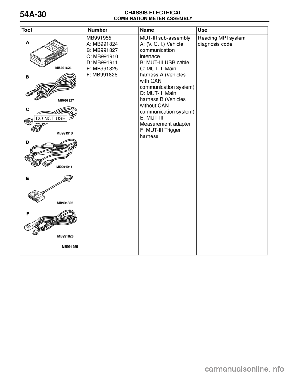
MB991955
A: MB991824
B: MB991827
C: MB991910
D: MB991911
E: MB991825
F: MB991826MUT-III sub-assembly
A: (V. C. I.) Vehicle
communication
interface
B: MUT-III USB cable
C: MUT-III Main
harness A (Vehicles
with CAN
communication system)
D: MUT-III Main
harness B (Vehicles
without CAN
communication system)
E: MUT-III
Measurement adapter
F: MUT-III Trigger
harnessReading MPI system
diagnosis code Tool Number Name Use
MB991910
MB991826
MB991955
MB991911
MB991824
MB991827
MB991825
A
B
C
D
E
F
DO NOT USE
Page 419 of 788

COMBINATION METER ASSEMBLY
CHASSIS ELECTRICAL54A-31
TROUBLESHOOTING
SYMPTOM CHARTM1543007201086
MB991223
A: MB991219
B: MB991220
C: MB991221
D: MB991222Harness set
A: Test harness
B: LED harness
C: LED harness
adapter
D: ProbeMaking voltage and
resistance measurements
during troubleshooting
A: Connect pin contact
pressure inspection
B: Power circuit inspection
C: Power circuit inspection
D: Commercial tester
connection Tool Number Name Use
MB991223
A
B
C
D
AC
Symptom Inspection
procedure No.Reference page
Speedometer does not work (the other meters work).
P.54A-32
Speedometer does not work (the other meters work). 2
P.54A-37
Tachometer does not work (the other meters work). 3
P.54A-44
Fuel gauge does not work (the other meters work). 4
P.54A-48
Engine coolant temperature gauge does not work (the other
meters work).5
P.54A-51
Combination meters does not work (the instruments do not
work).6
P.54A-54
Page 420 of 788
COMBINATION METER ASSEMBLY
CHASSIS ELECTRICAL54A-32
SYMPTOM PROCEDURES
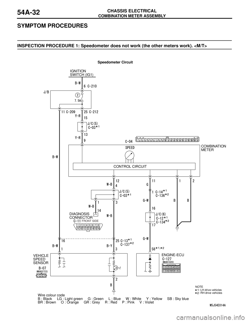
INSPECTION PROCEDURE 1: Speedometer does not work (the other meters work).
Speedometer Circuit
IGNITION
SWITCH (IG1)
VEHICLE
SPEED
SENSORDIAGNOSIS
CONNECTORCOMBINATION
METER
ENGINE-ECU
Wire colour code
B : Black LG : Light green G : Green L : Blue W : White Y : Yellow SB : Sky blue
BR : Brown O : Orange GR : Grey R : Red P : Pink V : Violet CONTROL CIRCUIT
FRONT SIDE
NOTE
LH drive vehicles
RH drive vehicles
,
Page 421 of 788
COMBINATION METER ASSEMBLY
CHASSIS ELECTRICAL54A-33
TECHNICAL DESCRIPTION (COMMENT)
The engine-ECU and its associated components, the
combination meter assembly, the wiring harness, or
the connector(s) may be defective.
TROUBLESHOOTING HINTS
•Malfunction of the vehicle speed sensor
•Malfunction of the engine-ECU
•Malfunction of the combination meter assembly
•The wiring harness or connectors may have
loose, corroded, or damaged terminals, or
terminals pushed back in the connector.
DIAGNOSIS PROCEDURE
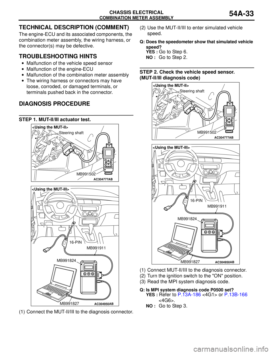
STEP 1. MUT-II/III actuator test.
(1) Connect the MUT-II/III to the diagnosis connector.(2) Use the MUT-II/III to enter simulated vehicle
speed.
Q: Does the speedometer show that simulated vehicle
speed?
YES :
Go to Step 6.
NO : Go to Step 2.
STEP 2. Check the vehicle speed sensor.
(MUT-II/III diagnosis code)
(1) Connect MUT-II/III to the diagnosis connector.
(2) Turn the ignition switch to the "ON" position.
(3) Read the MPI system diagnosis code.
Q: Is MPI system diagnosis code P0500 set?
YES :
Refer to P.13A-186 <4G1> or P.13B-166
<4G6>.
NO : Go to Step 3.
AC304777
Steering shaft
AB
MB991502
AC304950
MB991911
16-PIN
MB991827 MB991824
AB
AC304777
Steering shaft
AB
MB991502
AC304950
MB991911
16-PIN
MB991827 MB991824
AB
Page 422 of 788
COMBINATION METER ASSEMBLY
CHASSIS ELECTRICAL54A-34
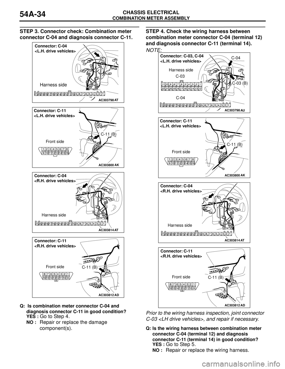
STEP 3. Connector check: Combination meter
connector C-04 and diagnosis connector C-11.
Q: Is combination meter connector C-04 and
diagnosis connector C-11 in good condition?
YES :
Go to Step 4.
NO : Repair or replace the damage
component(s).
STEP 4. Check the wiring harness between
combination meter connector C-04 (terminal 12)
and diagnosis connector C-11 (terminal 14).
NOTE:
Prior to the wiring harness inspection, joint connector
C-03
Q: Is the wiring harness between combination meter
connector C-04 (terminal 12) and diagnosis
connector C-11 (terminal 14) in good condition?
YES :
Go to Step 5.
NO : Repair or replace the wiring harness.
AC303798
Connector: C-04
Harness side
AT
AC303800
C-11 (B) Connector: C-11
Front side
AK
AC303814
Connector: C-04
Harness side
AT
AC303812
AD
Connector: C-11
Front side
C-11 (B)
AC303798AU
Connector: C-03, C-04
C-03 (B)
C-04 C-03 Harness side
AC303800
C-11 (B) Connector: C-11
Front side
AK
AC303814
Connector: C-04
Harness side
AT
AC303812
AD
Connector: C-11
Front side
C-11 (B)
Page 423 of 788
COMBINATION METER ASSEMBLY
CHASSIS ELECTRICAL54A-35
STEP 5. Retest the system
Q: Is the speedometer normal?
YES : .
The procedure is complete. (If no
malfunctions are found in all steps, an
intermittent malfunction is suspected. Refer
to GROUP 00, How to Use
Troubleshooting/Inspection Service
Points-How to Cope with Intermittent
Malfunction P.00-5).
NO : . Replace the combination meter assembly.
STEP 6. Check whether the diagnosis code is
reset.
Q: Is the MPI-related diagnosis code set?
YES :
Refer to GROUP 13A − Troubleshooting
P.13A-15, GROUP 13B − Troubleshooting
P.13B-15.
NO : . Go to Step 7.
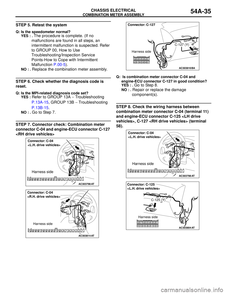
STEP 7. Connector check: Combination meter
connector C-04 and engine-ECU connector C-127
Q: Is combination meter connector C-04 and
engine-ECU connector C-127 in good condition?
YES : .
Go to Step 8.
NO : . Repair or replace the damage
component(s).
STEP 8. Check the wiring harness between
combination meter connector C-04 (terminal 11)
and engine-ECU connector C-125
58).
AC303798
Connector: C-04
Harness side
AT
AC303814
Connector: C-04
Harness side
AT
AC303816BA
Connector: C-127
C-127 (Y)
Harness side
AC303798
Connector: C-04
Harness side
AT
AC303804
Connector: C-125
C-125 (Y)
Harness side
51 52 53 54 55 56 57 58
66 65 64 63 62 61 60 59
AT
Page 424 of 788
COMBINATION METER ASSEMBLY
CHASSIS ELECTRICAL54A-36
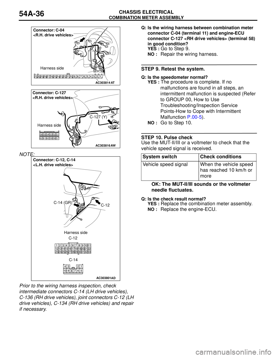
NOTE:
Prior to the wiring harness inspection, check
intermediate connectors C-14 (LH drive vehicles),
C-136 (RH drive vehicles), joint connectors C-12 (LH
drive vehicles), C-134 (RH drive vehicles) and repair
if necessary.
Q: Is the wiring harness between combination meter
connector C-04 (terminal 11) and engine-ECU
connector C-127
in good condition?
YES :
Go to Step 9.
NO : Repair the wiring harness.
STEP 9. Retest the system.
Q: Is the speedometer normal?
YES :
The procedure is complete. If no
malfunctions are found in all steps, an
intermittent malfunction is suspected (Refer
to GROUP 00, How to Use
Troubleshooting/Inspection Service
Points-How to Cope with Intermittent
Malfunction P.00-5).
NO : Go to Step 10.
STEP 10. Pulse check
Use the MUT-II/III or a voltmeter to check that the
vehicle speed signal is received.
OK: The MUT-II/III sounds or the voltmeter
needle fluctuates.
Q: Is the check result normal?
YES :
Replace the combination meter assembly.
NO : Replace the engine-ECU.
AC303814
Connector: C-04
Harness side
AT
AC303816AW
Connector: C-127
C-127 (Y)
Harness side
585261556256605459535751
AC303801
Connector: C-12, C-14
C-12C-14 (GR)
C-12
C-14 Harness side
AD
System switch Check conditions
Vehicle speed signal When the vehicle speed
has reached 10 km/h or
more