check MITSUBISHI LANCER 2005 Manual Online
[x] Cancel search | Manufacturer: MITSUBISHI, Model Year: 2005, Model line: LANCER, Model: MITSUBISHI LANCER 2005Pages: 788, PDF Size: 45.98 MB
Page 188 of 788
ON-VEHICLE SERVICE
FRONT SUSPENSION33-6
NOTE: The toe will move out as the left
turnbuckle is turned toward the front of the vehicle
and the right turnbuckle is turned toward the rear
of the vehicle.
2. Install the clip and tighten the lock nut to the
specified torque.
Tightening torque: 40 ± 5 N⋅m
3. Confirm that the toe-in is at the standard value.
4. Use a turning radius gauge to check that the
steering angle is at the standard value.
STEERING ANGLE
Standard value:
TOE-OUT ANGLE ON TURNS
To check the steering linkage, especially after the
vehicle has been involved in an accident or if an
accident is presumed, it is advisable to check the
toe-out angle on turns in addition to the wheel
alignment.
Conduct this test on the left turn as well as on the
right turn.
Standard value:
CAMBER, CASTER AND KINGPIN
INCLINATION
Standard value:NOTE: *: difference between right and left wheels
must be less than 30'
NOTE: Camber and caster are preset at the factory
and cannot be adjusted.
CAUTION
Never subject the wheel bearings to the vehicle
load when the driveshaft nuts are loosened.
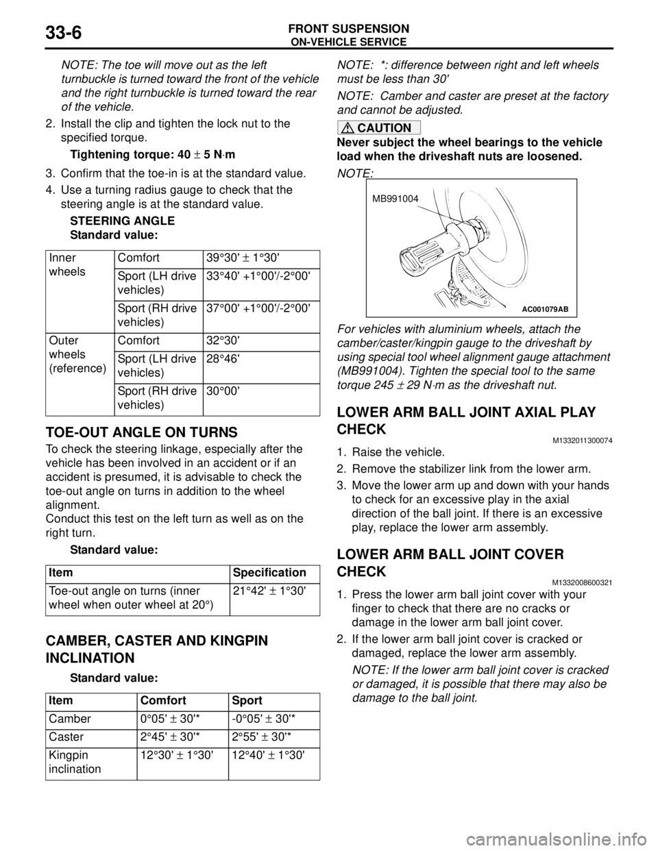
NOTE:
For vehicles with aluminium wheels, attach the
camber/caster/kingpin gauge to the driveshaft by
using special tool wheel alignment gauge attachment
(MB991004). Tighten the special tool to the same
torque 245
± 29 N⋅m as the driveshaft nut.
LOWER ARM BALL JOINT AXIAL PLAY
CHECK
M1332011300074
1. Raise the vehicle.
2. Remove the stabilizer link from the lower arm.
3. Move the lower arm up and down with your hands
to check for an excessive play in the axial
direction of the ball joint. If there is an excessive
play, replace the lower arm assembly.
LOWER ARM BALL JOINT COVER
CHECK
M1332008600321
1. Press the lower arm ball joint cover with your
finger to check that there are no cracks or
damage in the lower arm ball joint cover.
2. If the lower arm ball joint cover is cracked or
damaged, replace the lower arm assembly.
NOTE: If the lower arm ball joint cover is cracked
or damaged, it is possible that there may also be
damage to the ball joint. Inner
wheelsComfort 39°30' ± 1°30'
Sport (LH drive
vehicles)33°40' +1°00'/-2°00'
Sport (RH drive
vehicles)37°00' +1°00'/-2°00'
Outer
wheels
(reference)Comfort 32°30'
Sport (LH drive
vehicles)28°46'
Sport (RH drive
vehicles)30°00'
Item Specification
Toe-out angle on turns (inner
wheel when outer wheel at 20°)21°42' ± 1°30'
Item Comfort Sport
Camber 0°05' ± 30'* -0°05' ± 30'*
Caster 2°45' ± 30'* 2°55' ± 30'*
Kingpin
inclination12°30' ± 1°30' 12°40' ± 1°30'
AC001079
MB991004
AB
Page 189 of 788
STRUT ASSEMBLY
FRONT SUSPENSION33-7
STRUT ASSEMBLY
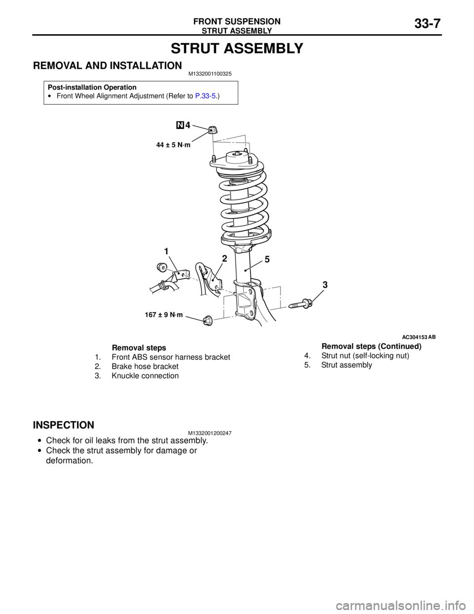
REMOVAL AND INSTALLATIONM1332001100325
INSPECTIONM1332001200247
•Check for oil leaks from the strut assembly.
•Check the strut assembly for damage or
deformation.
Post-installation Operation
•Front Wheel Alignment Adjustment (Refer to P.33-5.)
AC304153
44 ± 5 N·m
1
2
3 4
N
AB
167 ± 9 N·m
5
Removal steps
1. Front ABS sensor harness bracket
2. Brake hose bracket
3. Knuckle connection4. Strut nut (self-locking nut)
5. Strut assemblyRemoval steps (Continued)
Page 192 of 788
STRUT ASSEMBLY
FRONT SUSPENSION33-10
>>B<< STRUT NUT (SELF-LOCKING NUT)
INSTALLATION
1. Ensure that the bearing is seated correctly.
CAUTION
Do not use an impact wrench to tighten the bolt
of special tool spring compressor body
(MB991237), otherwise the special tool will break.
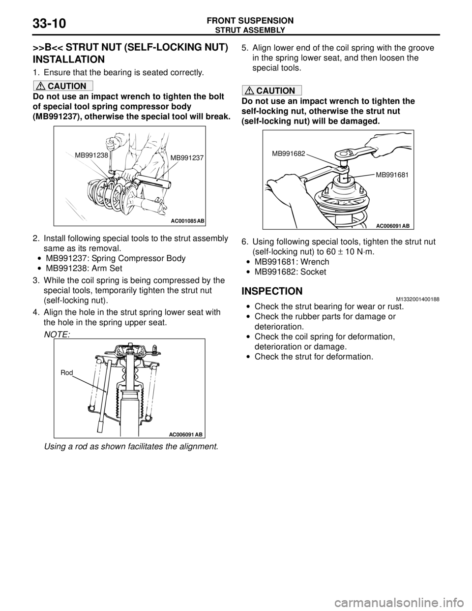
2. Install following special tools to the strut assembly
same as its removal.
•MB991237: Spring Compressor Body
•MB991238: Arm Set
3. While the coil spring is being compressed by the
special tools, temporarily tighten the strut nut
(self-locking nut).
4. Align the hole in the strut spring lower seat with
the hole in the spring upper seat.
NOTE:
Using a rod as shown facilitates the alignment.5. Align lower end of the coil spring with the groove
in the spring lower seat, and then loosen the
special tools.CAUTION
Do not use an impact wrench to tighten the
self-locking nut, otherwise the strut nut
(self-locking nut) will be damaged.
6. Using following special tools, tighten the strut nut
(self-locking nut) to 60 ± 10 N⋅m.
•MB991681: Wrench
•MB991682: Socket
INSPECTIONM1332001400188
•Check the strut bearing for wear or rust.
•Check the rubber parts for damage or
deterioration.
•Check the coil spring for deformation,
deterioration or damage.
•Check the strut for deformation.
AC001085 AB
MB991238
MB991237
AC006091 AB
Rod
AC006091 AB
MB991681 MB991682
Page 193 of 788
LOWER ARM
FRONT SUSPENSION33-11
LOWER ARM
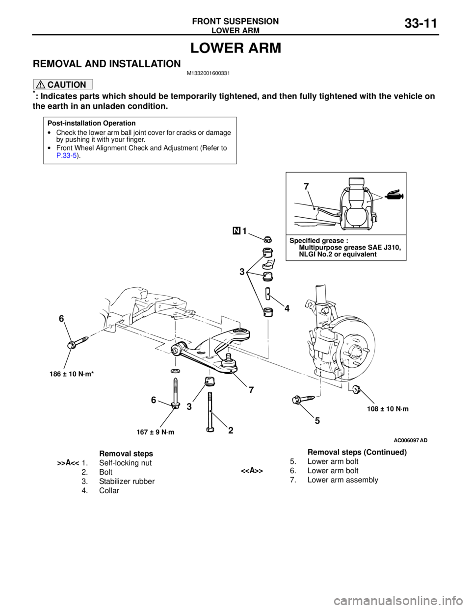
REMOVAL AND INSTALLATIONM1332001600331
CAUTION
*: Indicates parts which should be temporarily tightened, and then fully tightened with the vehicle on
the earth in an unladen condition.
Post-installation Operation
•Check the lower arm ball joint cover for cracks or damage
by pushing it with your finger.
•Front Wheel Alignment Check and Adjustment (Refer to
P.33-5).
AC006097AD
7
1
3
4
5
108 ± 10 N·m 186 ± 10 N·m*
7
3 6
N
Specified grease :
Multipurpose grease SAE J310,
NLGI No.2 or equivalent
167 ± 9 N·m
6
2
Removal steps
>>A<<1. Self-locking nut
2. Bolt
3. Stabilizer rubber
4. Collar5. Lower arm bolt<>6. Lower arm bolt
7. Lower arm assemblyRemoval steps (Continued)
Page 194 of 788
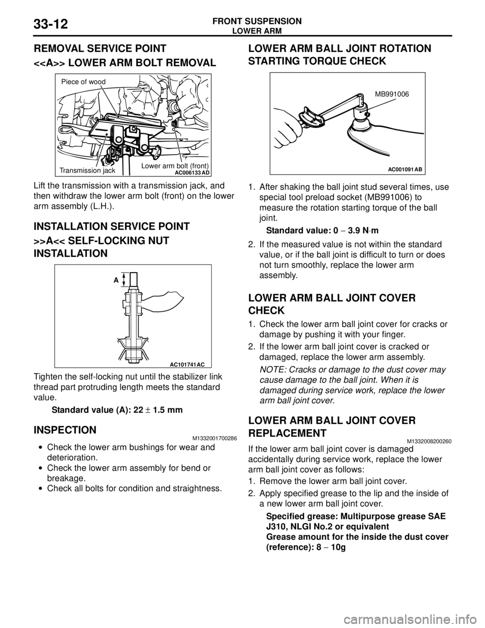
Page 195 of 788
LOWER ARM
FRONT SUSPENSION33-13
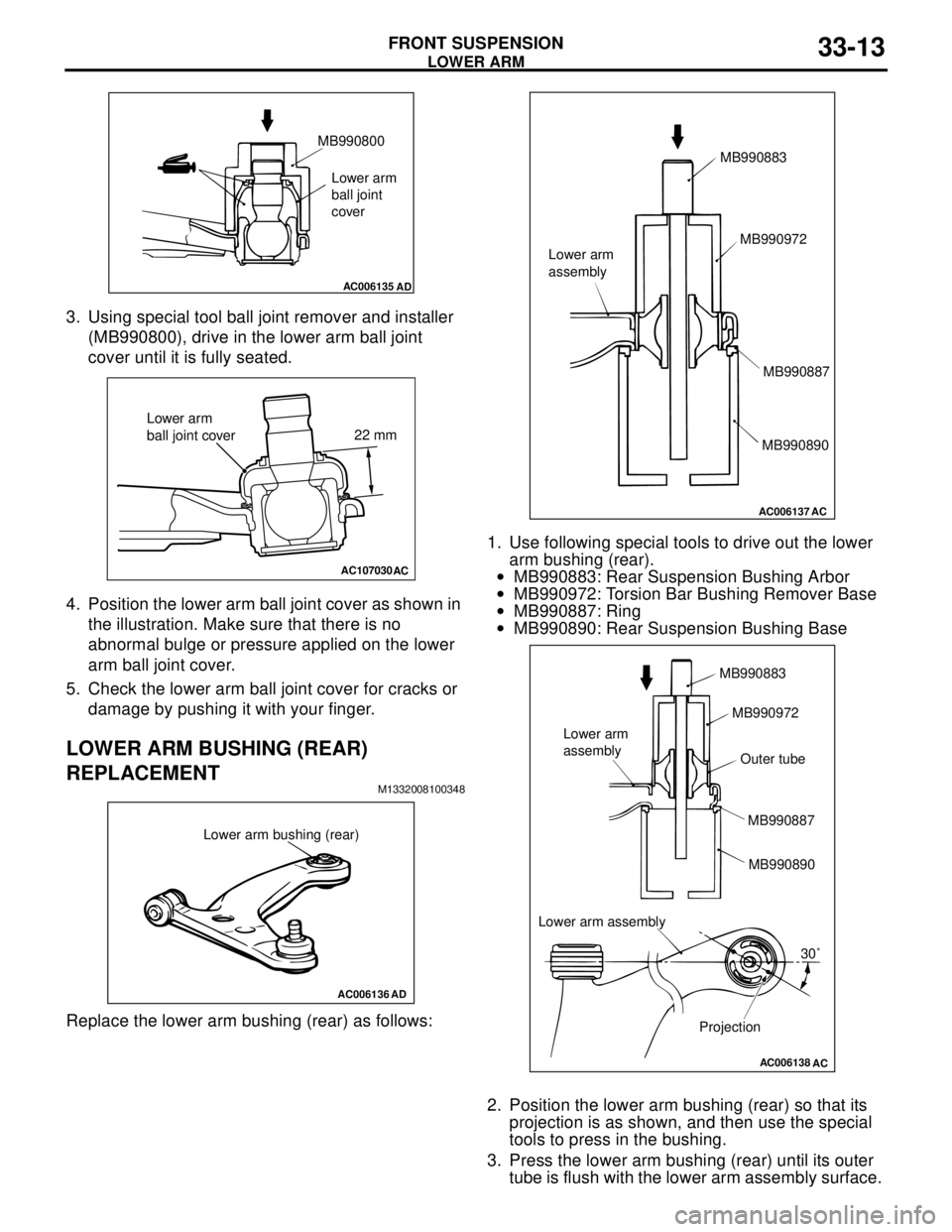
3. Using special tool ball joint remover and installer
(MB990800), drive in the lower arm ball joint
cover until it is fully seated.
4. Position the lower arm ball joint cover as shown in
the illustration. Make sure that there is no
abnormal bulge or pressure applied on the lower
arm ball joint cover.
5. Check the lower arm ball joint cover for cracks or
damage by pushing it with your finger.
LOWER ARM BUSHING (REAR)
REPLACEMENT
M1332008100348
Replace the lower arm bushing (rear) as follows:1. Use following special tools to drive out the lower
arm bushing (rear).
•MB990883: Rear Suspension Bushing Arbor
•MB990972: Torsion Bar Bushing Remover Base
•MB990887: Ring
•MB990890: Rear Suspension Bushing Base
2. Position the lower arm bushing (rear) so that its
projection is as shown, and then use the special
tools to press in the bushing.
3. Press the lower arm bushing (rear) until its outer
tube is flush with the lower arm assembly surface.
AC006135
AD
MB990800
Lower arm
ball joint
cover
AC107030AC
22 mm
Lower arm
ball joint cover
AC006136
AD
Lower arm bushing (rear)
AC006137
AC
MB990883
MB990972
MB990887
MB990890 Lower arm
assembly
AC006138
AC
MB990883
MB990972
MB990887
MB990890 Lower arm
assembly
Projection30˚ Lower arm assemblyOuter tube
Page 196 of 788
STABILIZER BAR
FRONT SUSPENSION33-14
STABILIZER BAR
REMOVAL AND INSTALLATIONM1332004000468
CAUTION
•Before removing the steering wheel and air bag module assembly, refer to GROUP 52B, Service
Precautions P.52B-5 and Air Bag Module and Clock Spring P.52B-210. Also, put the front wheels in
straight-ahead position. Failure to do so may damage the SRS clock spring and render the SRS air
bag inoperative, which results serious driver injury.
•
*: Indicates parts which should be initially tightened, and then fully tightened after placing the
vehicle horizontally and loading the full weight of the engine on the vehicle body.
Pre-removal Operation
•Steering Wheel and Air Bag Module Assembly Removal
(Comfort: refer to GROUP 37, Steering Wheel
P.37-17/Sport: refer to GROUP 37, Steering Wheel
P.37-19).
•Clock Spring Removal (Refer to GROUP 52B, Air Bag
Modules and Clock Spring P.52B-210).
•Centermember Removal (Refer to GROUP 32, Engine
Roll Stopper, Centermember P.32-7).
•Front Exhaust Pipe Removal (Refer to GROUP 15,
Exhaust Pipe and Main Muffler P.15-11).Post-installation Operation
•Front Exhaust Pipe Installation (Refer to GROUP 15,
Exhaust Pipe and Main Muffler P.15-11).
•Centermember Installation (Refer to GROUP 32, Engine
Roll Stopper, Centermember P.32-7).
•Clock Spring Installation (Refer to GROUP 52B, Air Bag
Modules and Clock Spring P.52B-210).
•Steering Wheel and Air Bag Module Assembly Installation
(Comfort: refer to GROUP 37, Steering Wheel
P.37-17/Sport: refer to GROUP 37, Steering Wheel
P.37-19).
•Check the dust covers for cracks or damage by pushing it
with your finger.
•Checking Steering Wheel Position with Wheels Straight
Ahead
•Front Wheel Alignment Check and Adjustment (Refer to
P.33-5).
Page 199 of 788
STABILIZER BAR
FRONT SUSPENSION33-17
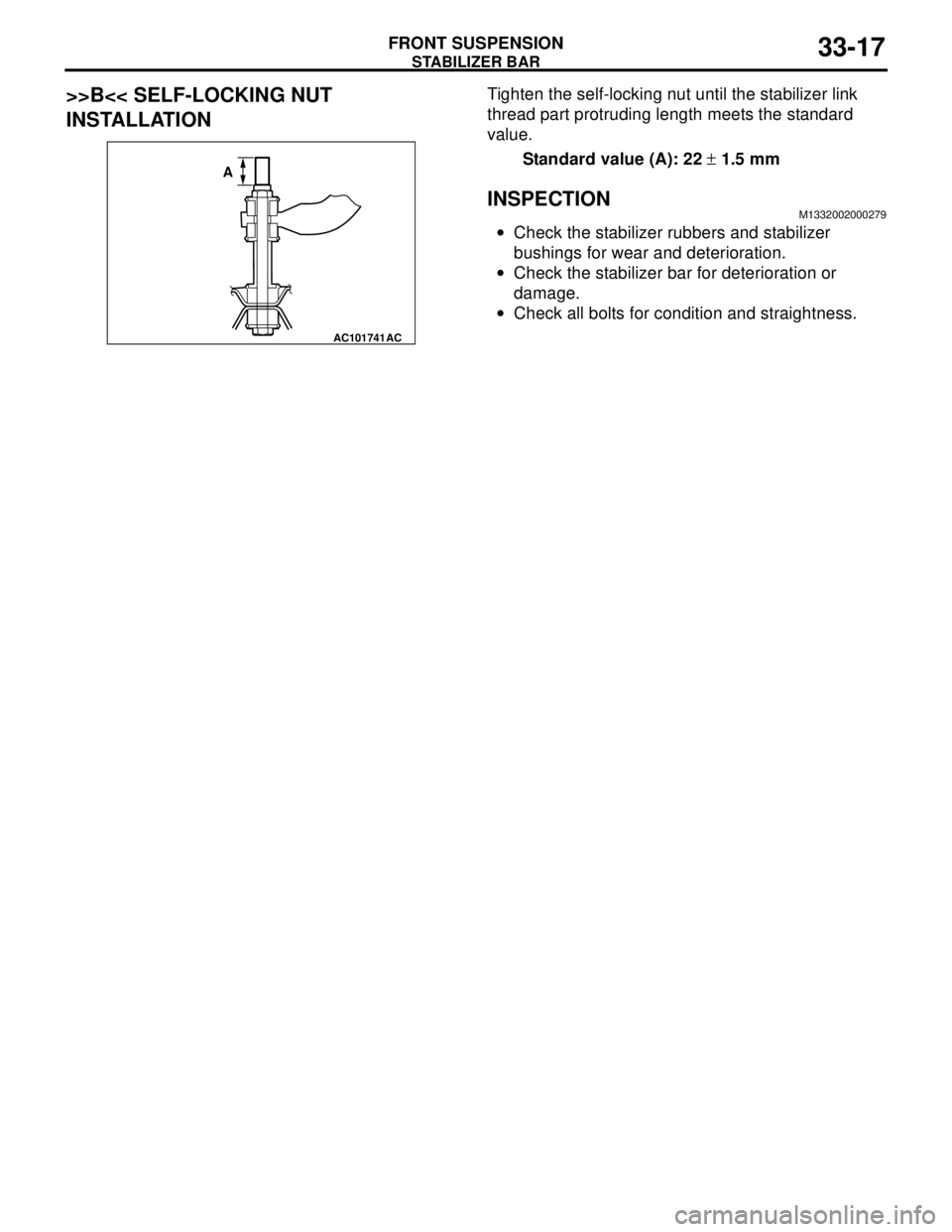
>>B<< SELF-LOCKING NUT
INSTALLATIONTighten the self-locking nut until the stabilizer link
thread part protruding length meets the standard
value.
Standard value (A): 22 ± 1.5 mm
INSPECTIONM1332002000279
•Check the stabilizer rubbers and stabilizer
bushings for wear and deterioration.
•Check the stabilizer bar for deterioration or
damage.
•Check all bolts for condition and straightness.
AC101741AC
A
Page 201 of 788
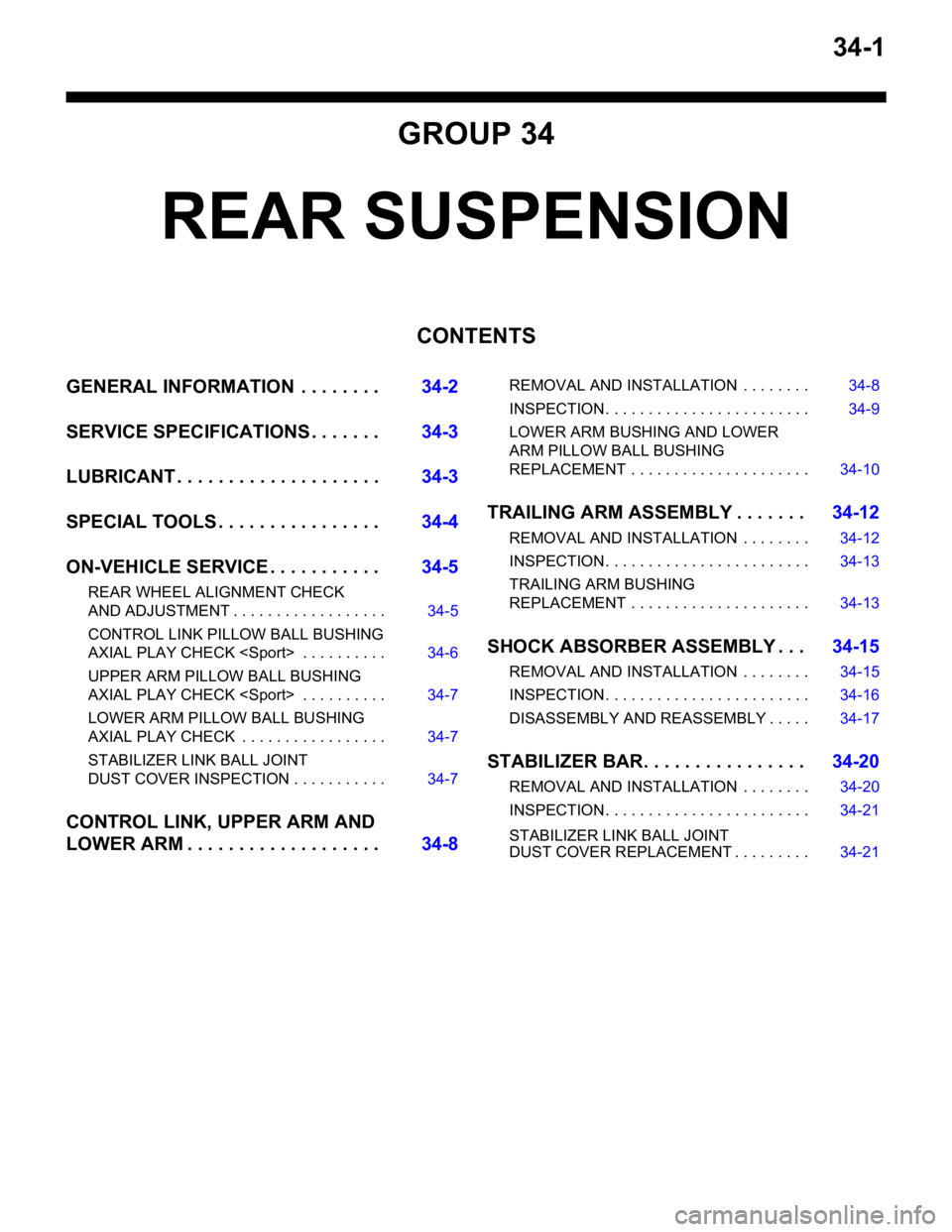
34-1
GROUP 34
REAR SUSPENSION
CONTENTS
GENERAL INFORMATION . . . . . . . .34-2
SERVICE SPECIFICATIONS . . . . . . .34-3
LUBRICANT . . . . . . . . . . . . . . . . . . . .34-3
SPECIAL TOOLS . . . . . . . . . . . . . . . .34-4
ON-VEHICLE SERVICE . . . . . . . . . . .34-5
REAR WHEEL ALIGNMENT CHECK
AND ADJUSTMENT . . . . . . . . . . . . . . . . . . 34-5
CONTROL LINK PILLOW BALL BUSHING
AXIAL PLAY CHECK
UPPER ARM PILLOW BALL BUSHING
AXIAL PLAY CHECK
LOWER ARM PILLOW BALL BUSHING
AXIAL PLAY CHECK . . . . . . . . . . . . . . . . . 34-7
STABILIZER LINK BALL JOINT
DUST COVER INSPECTION . . . . . . . . . . . 34-7
CONTROL LINK, UPPER ARM AND
LOWER ARM . . . . . . . . . . . . . . . . . . .34-8
REMOVAL AND INSTALLATION . . . . . . . . 34-8
INSPECTION . . . . . . . . . . . . . . . . . . . . . . . . 34-9
LOWER ARM BUSHING AND LOWER
ARM PILLOW BALL BUSHING
REPLACEMENT . . . . . . . . . . . . . . . . . . . . . 34-10
TRAILING ARM ASSEMBLY . . . . . . .34-12
REMOVAL AND INSTALLATION . . . . . . . . 34-12
INSPECTION . . . . . . . . . . . . . . . . . . . . . . . . 34-13
TRAILING ARM BUSHING
REPLACEMENT . . . . . . . . . . . . . . . . . . . . . 34-13
SHOCK ABSORBER ASSEMBLY . . .34-15
REMOVAL AND INSTALLATION . . . . . . . . 34-15
INSPECTION . . . . . . . . . . . . . . . . . . . . . . . . 34-16
DISASSEMBLY AND REASSEMBLY . . . . . 34-17
STABILIZER BAR. . . . . . . . . . . . . . . .34-20
REMOVAL AND INSTALLATION . . . . . . . . 34-20
INSPECTION . . . . . . . . . . . . . . . . . . . . . . . . 34-21
STABILIZER LINK BALL JOINT
DUST COVER REPLACEMENT . . . . . . . . . 34-21
Page 204 of 788
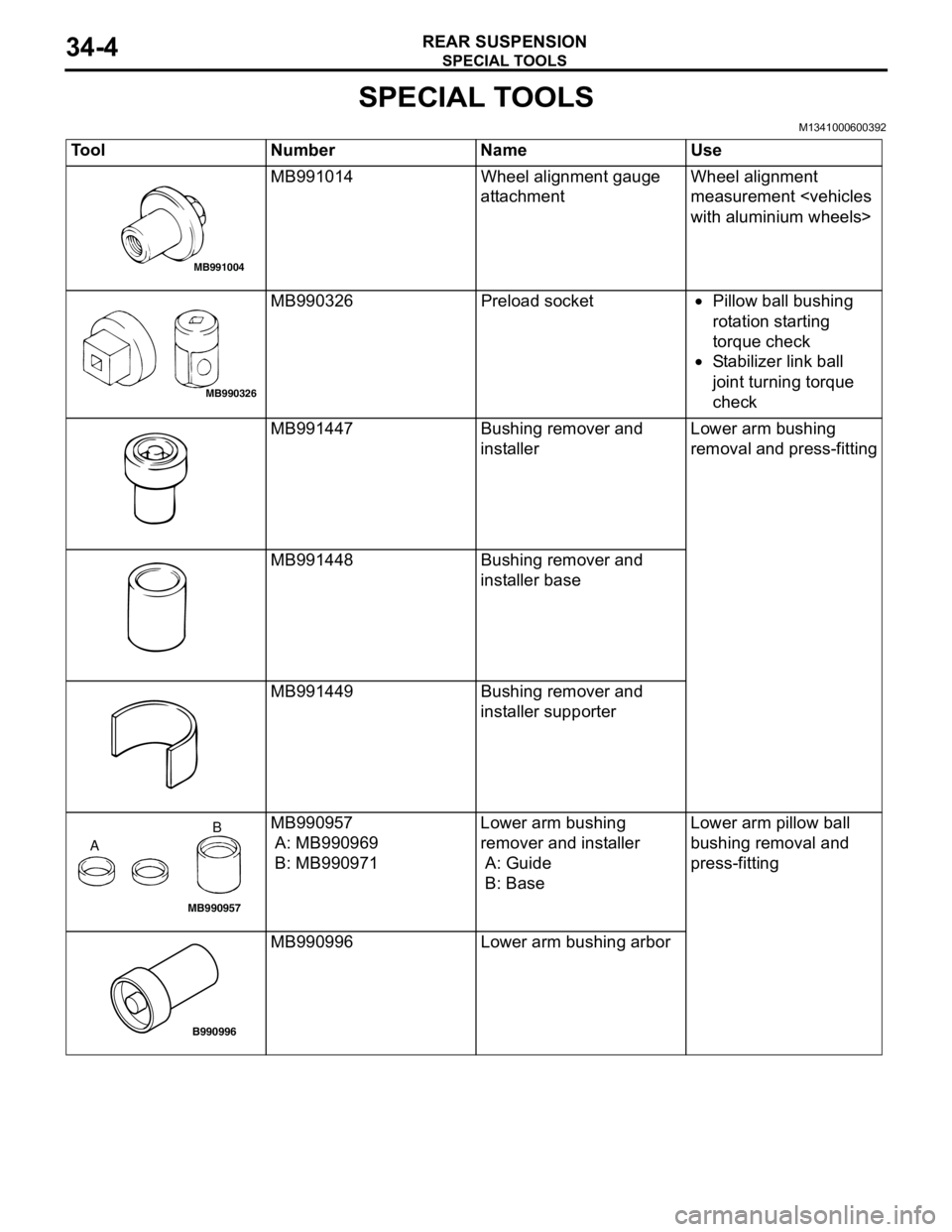
SPECIAL TOOLS
REAR SUSPENSION34-4
SPECIAL TOOLS
M1341000600392
Tool Number Name Use
MB991014 Wheel alignment gauge
attachmentWheel alignment
measurement
MB990326 Preload socket•Pillow ball bushing
rotation starting
torque check
•Stabilizer link ball
joint turning torque
check
MB991447 Bushing remover and
installerLower arm bushing
removal and press-fitting
MB991448 Bushing remover and
installer base
MB991449 Bushing remover and
installer supporter
MB990957
A: MB990969
B: MB990971Lower arm bushing
remover and installer
A: Guide
B: BaseLower arm pillow ball
bushing removal and
press-fitting
MB990996 Lower arm bushing arbor
MB991004
MB990326
MB990957
AB
B990996