check MITSUBISHI LANCER 2005 Repair Manual
[x] Cancel search | Manufacturer: MITSUBISHI, Model Year: 2005, Model line: LANCER, Model: MITSUBISHI LANCER 2005Pages: 788, PDF Size: 45.98 MB
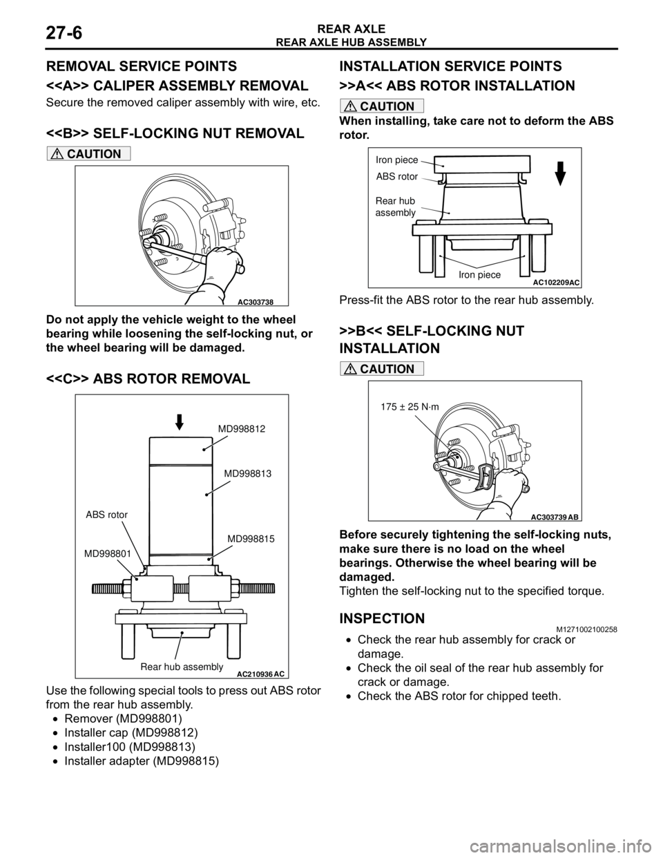
Page 140 of 788
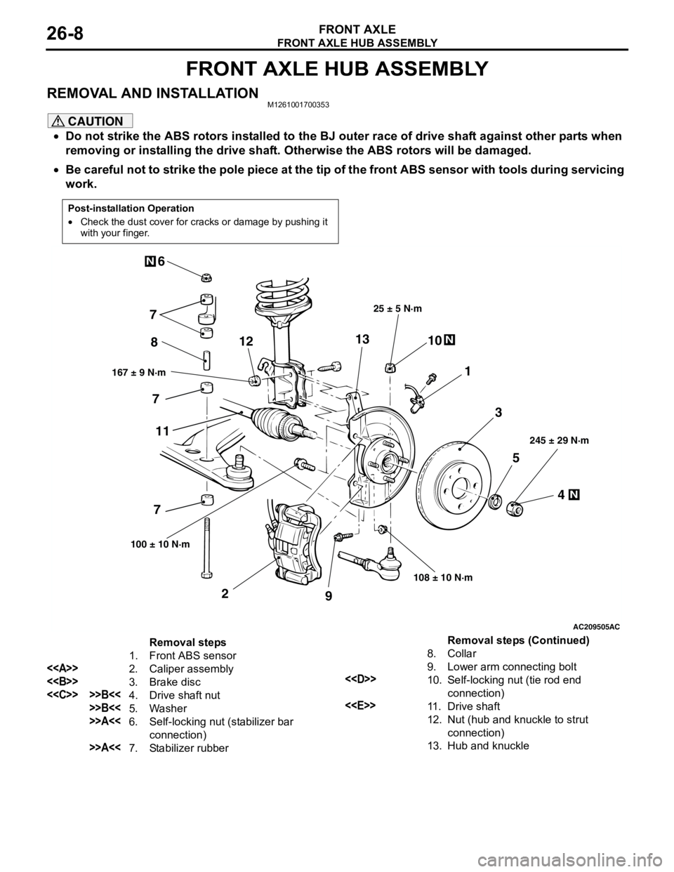
FRONT AXLE HUB ASSEMBLY
FRONT AXLE26-8
FRONT AXLE HUB ASSEMBLY
REMOVAL AND INSTALLATIONM1261001700353
CAUTION
•Do not strike the ABS rotors installed to the BJ outer race of drive shaft against other parts when
removing or installing the drive shaft. Otherwise the ABS rotors will be damaged.
•Be careful not to strike the pole piece at the tip of the front ABS sensor with tools during servicing
work.
Post-installation Operation
•Check the dust cover for cracks or damage by pushing it
with your finger.
AC209505
N
N
N
5
4 3 1 810
9 2 76
167 ± 9 N·m25 ± 5 N·m
108 ± 10 N·m245 ± 29 N·m
100 ± 10 N·m
AC
7
7
111213
Removal steps
1. Front ABS sensor
<>
2. Caliper assembly
<>
3. Brake disc
<
>>B<<5. Washer
>>A<<6. Self-locking nut (stabilizer bar
connection)
>>A<<7. Stabilizer rubber8. Collar
9. Lower arm connecting bolt
<
10. Self-locking nut (tie rod end
connection)
<
11 . D r i v e s h a f t
12. Nut (hub and knuckle to strut
connection)
13. Hub and knuckle
Removal steps (Continued)
Page 143 of 788
FRONT AXLE HUB ASSEMBLY
FRONT AXLE26-11
INSPECTIONM1261001800242
•Check the hub for cracks and spline for wear.
•Check the knuckle for cracks.
•Check for defective bearing.NOTE: If the meshing of the wheel bearing outer
race and the knuckle, or of the wheel bearing
inner race and the hub, is loose, replace the
bearing or damaged parts.
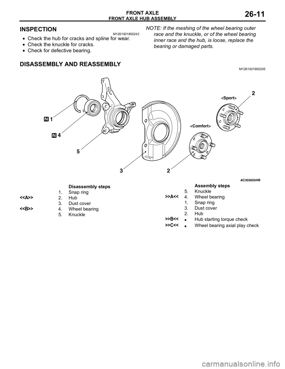
DISASSEMBLY AND REASSEMBLYM1261001900205
AC303659
N
N4 1
5
32
AB
2
Disassembly steps
1. Snap ring
<>2. Hub
3. Dust cover
<>4. Wheel bearing
5. KnuckleAssembly steps
5. Knuckle
>>A<<4. Wheel bearing
1. Snap ring
3. Dust cover
2. Hub
>>B<<•Hub starting torque check
>>C<<•Wheel bearing axial play check
Page 145 of 788
FRONT AXLE HUB ASSEMBLY
FRONT AXLE26-13
REASSEMBLY SERVICE POINTS
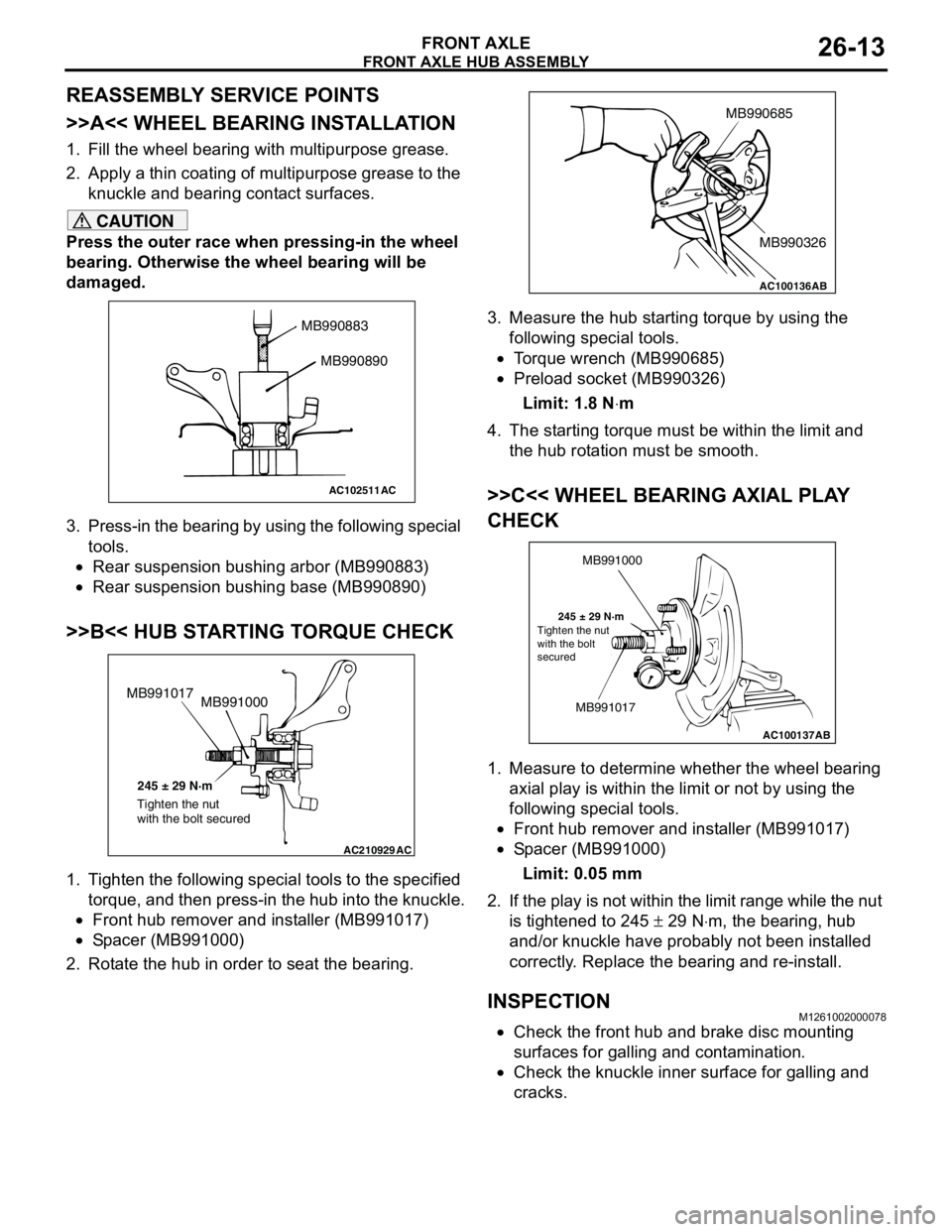
>>A<< WHEEL BEARING INSTALLATION
1. Fill the wheel bearing with multipurpose grease.
2. Apply a thin coating of multipurpose grease to the
knuckle and bearing contact surfaces.
CAUTION
Press the outer race when pressing-in the wheel
bearing. Otherwise the wheel bearing will be
damaged.
3. Press-in the bearing by using the following special
tools.
•Rear suspension bushing arbor (MB990883)
•Rear suspension bushing base (MB990890)
>>B<< HUB STARTING TORQUE CHECK
1. Tighten the following special tools to the specified
torque, and then press-in the hub into the knuckle.
•Front hub remover and installer (MB991017)
•Spacer (MB991000)
2. Rotate the hub in order to seat the bearing.3. Measure the hub starting torque by using the
following special tools.
•Torque wrench (MB990685)
•Preload socket (MB990326)
Limit: 1.8 N⋅m
4. The starting torque must be within the limit and
the hub rotation must be smooth.
>>C<< WHEEL BEARING AXIAL PLAY
CHECK
1. Measure to determine whether the wheel bearing
axial play is within the limit or not by using the
following special tools.
•Front hub remover and installer (MB991017)
•Spacer (MB991000)
Limit: 0.05 mm
2. If the play is not within the limit range while the nut
is tightened to 245 ± 29 N⋅m, the bearing, hub
and/or knuckle have probably not been installed
correctly. Replace the bearing and re-install.
INSPECTIONM1261002000078
•Check the front hub and brake disc mounting
surfaces for galling and contamination.
•Check the knuckle inner surface for galling and
cracks.
AC102511
MB990883
MB990890
AC
AC210929AC
MB991000 MB991017
245 ± 29 N·m
Tighten the nut
with the bolt secured
AC100136
MB990685
MB990326
AB
AC100137
MB991000
MB991017
245 ± 29 N·m
AB Tighten the nut
with the bolt
secured
Page 146 of 788
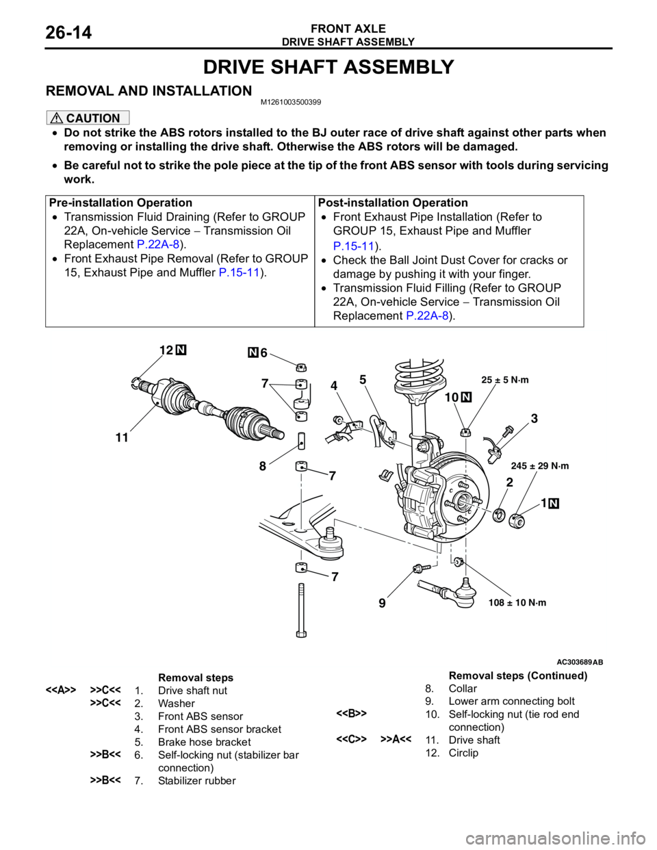
DRIVE SHAFT ASSEMBLY
FRONT AXLE26-14
DRIVE SHAFT ASSEMBLY
REMOVAL AND INSTALLATIONM1261003500399
CAUTION
•Do not strike the ABS rotors installed to the BJ outer race of drive shaft against other parts when
removing or installing the drive shaft. Otherwise the ABS rotors will be damaged.
•Be careful not to strike the pole piece at the tip of the front ABS sensor with tools during servicing
work.
Pre-installation Operation
•Transmission Fluid Draining (Refer to GROUP
22A, On-vehicle Service − Transmission Oil
Replacement P.22A-8).
•Front Exhaust Pipe Removal (Refer to GROUP
15, Exhaust Pipe and Muffler P.15-11).Post-installation Operation
•Front Exhaust Pipe Installation (Refer to
GROUP 15, Exhaust Pipe and Muffler
P.15-11).
•Check the Ball Joint Dust Cover for cracks or
damage by pushing it with your finger.
•Transmission Fluid Filling (Refer to GROUP
22A, On-vehicle Service − Transmission Oil
Replacement P.22A-8).
AC303689AB
9
N
N
NN
10 7
4
3
2
1
25 ± 5 N·m
245 ± 29 N·m
108 ± 10 N·m
8
5 6
1112
7
7
Removal steps
<> >>C<<1. Drive shaft nut
>>C<<2. Washer
3. Front ABS sensor
4. Front ABS sensor bracket
5. Brake hose bracket
>>B<<6. Self-locking nut (stabilizer bar
connection)
>>B<<7. Stabilizer rubber8. Collar
9. Lower arm connecting bolt
<>10. Self-locking nut (tie rod end
connection)
<
12. CirclipRemoval steps (Continued)
Page 153 of 788
DRIVE SHAFT ASSEMBLY
FRONT AXLE26-21
INSPECTIONM1261003800130
•Check the drive shaft for damage, bending or
corrosion.
•Check the drive shaft spline part for wear or
damage.
•Check the spider assembly for roller rotation,
wear or corrosion.
•Check the groove inside TJ case for wear or
corrosion.
•Check the dynamic damper for damage or
cracking.
•Check the boots for deterioration, damage or
cracking.
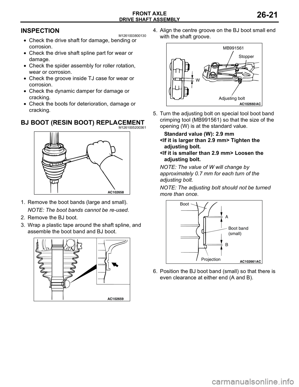
BJ BOOT (RESIN BOOT) REPLACEMENTM1261005200361
1. Remove the boot bands (large and small).
NOTE: The boot bands cannot be re-used.
2. Remove the BJ boot.
3. Wrap a plastic tape around the shaft spline, and
assemble the boot band and BJ boot.4. Align the centre groove on the BJ boot small end
with the shaft groove.
5. Turn the adjusting bolt on special tool boot band
crimping tool (MB991561) so that the size of the
opening (W) is at the standard value.
Standard value (W): 2.9 mm
adjusting bolt.
adjusting bolt.
NOTE: The value of W will change by
approximately 0.7 mm for each turn of the
adjusting bolt.
NOTE: The adjusting bolt should not be turned
more than once.
6. Position the BJ boot band (small) so that there is
even clearance at either end (A and B).
AC102658
AC102659
AC102660
WMB991561
Stopper
Adjusting bolt
AC
AC102661AC
Boot
A
Boot band
(small)
B
Projection
Page 154 of 788
DRIVE SHAFT ASSEMBLY
FRONT AXLE26-22
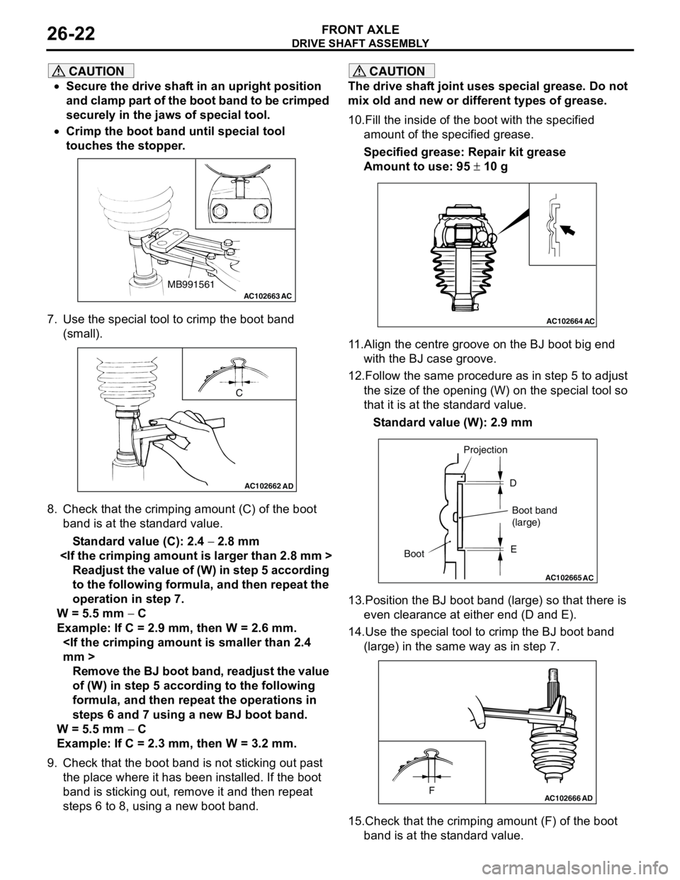
CAUTION
•Secure the drive shaft in an upright position
and clamp part of the boot band to be crimped
securely in the jaws of special tool.
•Crimp the boot band until special tool
touches the stopper.
7. Use the special tool to crimp the boot band
(small).
8. Check that the crimping amount (C) of the boot
band is at the standard value.
Standard value (C): 2.4 − 2.8 mm
Readjust the value of (W) in step 5 according
to the following formula, and then repeat the
operation in step 7.
W = 5.5 mm − C
Example: If C = 2.9 mm, then W = 2.6 mm.
Remove the BJ boot band, readjust the value
of (W) in step 5 according to the following
formula, and then repeat the operations in
steps 6 and 7 using a new BJ boot band.
W = 5.5 mm − C
Example: If C = 2.3 mm, then W = 3.2 mm.
9. Check that the boot band is not sticking out past
the place where it has been installed. If the boot
band is sticking out, remove it and then repeat
steps 6 to 8, using a new boot band.
CAUTION
The drive shaft joint uses special grease. Do not
mix old and new or different types of grease.
10.Fill the inside of the boot with the specified
amount of the specified grease.
Specified grease: Repair kit grease
Amount to use: 95 ± 10 g
11.Align the centre groove on the BJ boot big end
with the BJ case groove.
12.Follow the same procedure as in step 5 to adjust
the size of the opening (W) on the special tool so
that it is at the standard value.
Standard value (W): 2.9 mm
13.Position the BJ boot band (large) so that there is
even clearance at either end (D and E).
14.Use the special tool to crimp the BJ boot band
(large) in the same way as in step 7.
15.Check that the crimping amount (F) of the boot
band is at the standard value.
AC102663 ACMB991561
AC102662
C
AD
AC102664AC
AC102665
AC
BootProjection
Boot band
(large) D
E
AC102666FAD
Page 155 of 788
DRIVE SHAFT ASSEMBLY
FRONT AXLE26-23
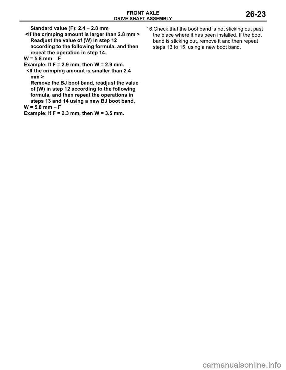
Standard value (F): 2.4 − 2.8 mm
Readjust the value of (W) in step 12
according to the following formula, and then
repeat the operation in step 14.
W = 5.8 mm − F
Example: If F = 2.9 mm, then W = 2.9 mm.
Remove the BJ boot band, readjust the value
of (W) in step 12 according to the following
formula, and then repeat the operations in
steps 13 and 14 using a new BJ boot band.
W = 5.8 mm − F
Example: If F = 2.3 mm, then W = 3.5 mm.16.Check that the boot band is not sticking out past
the place where it has been installed. If the boot
band is sticking out, remove it and then repeat
steps 13 to 15, using a new boot band.
Page 157 of 788
27-1
GROUP 27
REAR AXLE
CONTENTS
GENERAL INFORMATION . . . . . . . .27-2
SERVICE SPECIFICATIONS . . . . . . .27-2
SEALANT . . . . . . . . . . . . . . . . . . . . . .27-2
SPECIAL TOOLS . . . . . . . . . . . . . . . .27-3ON-VEHICLE SERVICE . . . . . . . . . . .27-4
WHEEL BEARING AXIAL PLAY CHECK . . 27-4
REAR HUB ROTARY-SLIDING
RESISTANCE CHECK . . . . . . . . . . . . . . . . 27-4
HUB BOLT REPLACEMENT . . . . . . . . . . . . 27-4
REAR AXLE HUB ASSEMBLY . . . . .27-5
REMOVAL AND INSTALLATION . . . . . . . . 27-5
INSPECTION . . . . . . . . . . . . . . . . . . . . . . . . 27-6
Page 160 of 788
ON-VEHICLE SERVICE
REAR AXLE27-4
ON-VEHICLE SERVICE
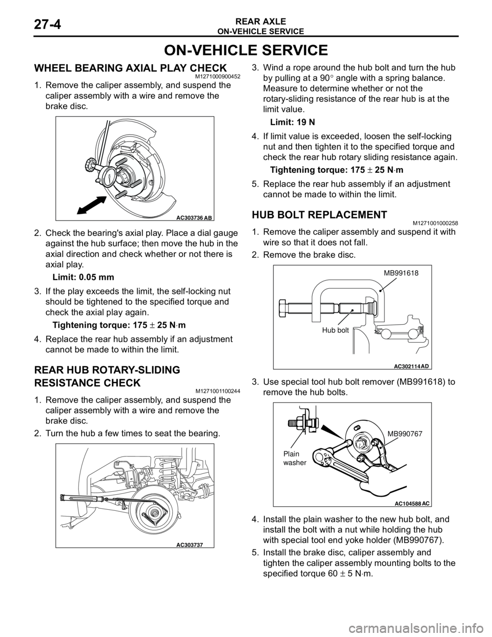
WHEEL BEARING AXIAL PLAY CHECKM1271000900452
1. Remove the caliper assembly, and suspend the
caliper assembly with a wire and remove the
brake disc.
2. Check the bearing's axial play. Place a dial gauge
against the hub surface; then move the hub in the
axial direction and check whether or not there is
axial play.
Limit: 0.05 mm
3. If the play exceeds the limit, the self-locking nut
should be tightened to the specified torque and
check the axial play again.
Tightening torque: 175 ± 25 N⋅m
4. Replace the rear hub assembly if an adjustment
cannot be made to within the limit.
REAR HUB ROTARY-SLIDING
RESISTANCE CHECK
M1271001100244
1. Remove the caliper assembly, and suspend the
caliper assembly with a wire and remove the
brake disc.
2. Turn the hub a few times to seat the bearing.3. Wind a rope around the hub bolt and turn the hub
by pulling at a 90° angle with a spring balance.
Measure to determine whether or not the
rotary-sliding resistance of the rear hub is at the
limit value.
Limit: 19 N
4. If limit value is exceeded, loosen the self-locking
nut and then tighten it to the specified torque and
check the rear hub rotary sliding resistance again.
Tightening torque: 175 ± 25 N⋅m
5. Replace the rear hub assembly if an adjustment
cannot be made to within the limit.
HUB BOLT REPLACEMENTM1271001000258
1. Remove the caliper assembly and suspend it with
wire so that it does not fall.
2. Remove the brake disc.
3. Use special tool hub bolt remover (MB991618) to
remove the hub bolts.
4. Install the plain washer to the new hub bolt, and
install the bolt with a nut while holding the hub
with special tool end yoke holder (MB990767).
5. Install the brake disc, caliper assembly and
tighten the caliper assembly mounting bolts to the
specified torque 60 ± 5 N⋅m.
AC303736AB
AC303737
AC302114
MB991618
AD
Hub bolt
AC104588
MB990767
Plain
washer
AC
Page 162 of 788