check MITSUBISHI LANCER 2005 Workshop Manual
[x] Cancel search | Manufacturer: MITSUBISHI, Model Year: 2005, Model line: LANCER, Model: MITSUBISHI LANCER 2005Pages: 788, PDF Size: 45.98 MB
Page 268 of 788
POWER STEERING GEAR BOX AND LINKAGE
POWER STEERING37-34
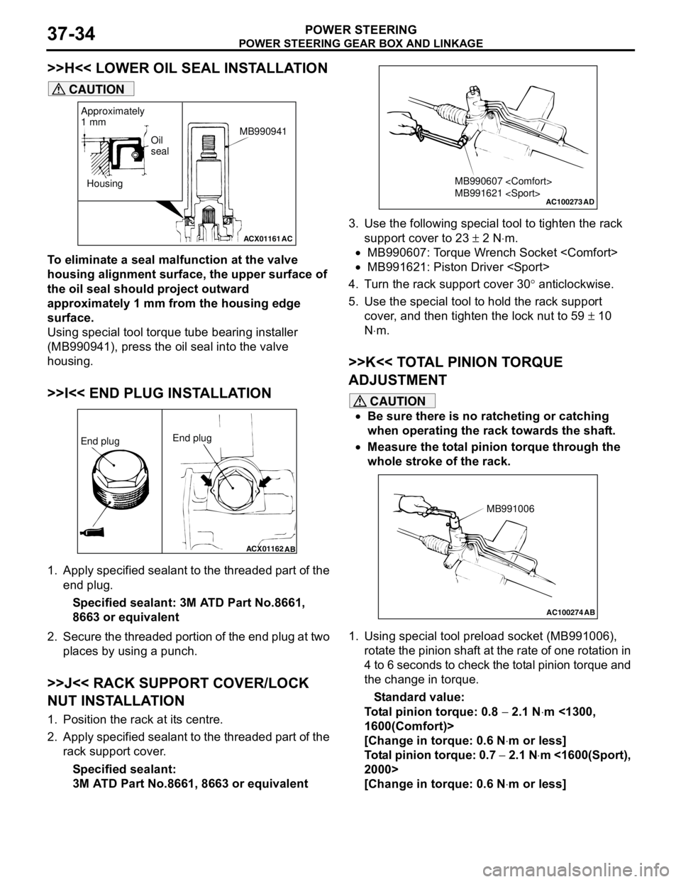
>>H<< LOWER OIL SEAL INSTALLATION
CAUTION
To eliminate a seal malfunction at the valve
housing alignment surface, the upper surface of
the oil seal should project outward
approximately 1 mm from the housing edge
surface.
Using special tool torque tube bearing installer
(MB990941), press the oil seal into the valve
housing.
>>I<< END PLUG INSTALLATION
1. Apply specified sealant to the threaded part of the
end plug.
Specified sealant: 3M ATD Part No.8661,
8663 or equivalent
2. Secure the threaded portion of the end plug at two
places by using a punch.
>>J<< RACK SUPPORT COVER/LOCK
NUT INSTALLATION
1. Position the rack at its centre.
2. Apply specified sealant to the threaded part of the
rack support cover.
Specified sealant:
3M ATD Part No.8661, 8663 or equivalent3. Use the following special tool to tighten the rack
support cover to 23 ± 2 N⋅m.
•MB990607: Torque Wrench Socket
•MB991621: Piston Driver
4. Turn the rack support cover 30° anticlockwise.
5. Use the special tool to hold the rack support
cover, and then tighten the lock nut to 59 ± 10
N⋅m.
>>K<< TOTAL PINION TORQUE
ADJUSTMENT
CAUTION
•Be sure there is no ratcheting or catching
when operating the rack towards the shaft.
•Measure the total pinion torque through the
whole stroke of the rack.
1. Using special tool preload socket (MB991006),
rotate the pinion shaft at the rate of one rotation in
4 to 6 seconds to check the total pinion torque and
the change in torque.
Standard value:
Total pinion torque: 0.8 − 2.1 N⋅m <1300,
1600(Comfort)>
[Change in torque: 0.6 N⋅m or less]
Total pinion torque: 0.7 − 2.1 N⋅m <1600(Sport),
2000>
[Change in torque: 0.6 N⋅m or less]
ACX01161
Housing
AC
Oil
seal
Approximately
1 mm
MB990941
ACX01162
AB
End plugEnd plug
AC100273
MB990607
MB991621
AD
AC100274 AB
MB991006
Page 269 of 788
POWER STEERING GEAR BOX AND LINKAGE
POWER STEERING37-35
CAUTION
When adjusting, set at the highest value of the
standard value range.
NOTE: If the total pinion toque cannot be adjusted
to the standard value within the specified return
angle, check the rack support cover components
and replace any parts if necessary.
2. If the total pinion torque or the change in torque is
outside the standard value, move the rack support
cover 0 − 30°, and adjust the pinion torque again.
>>L<< TAB WASHER/TIE ROD
INSTALLATION
After installing the tie rod to the rack, fold tab washer
end (two locations) to tie rod notch.
>>M<< BELLOWS BAND INSTALLATION
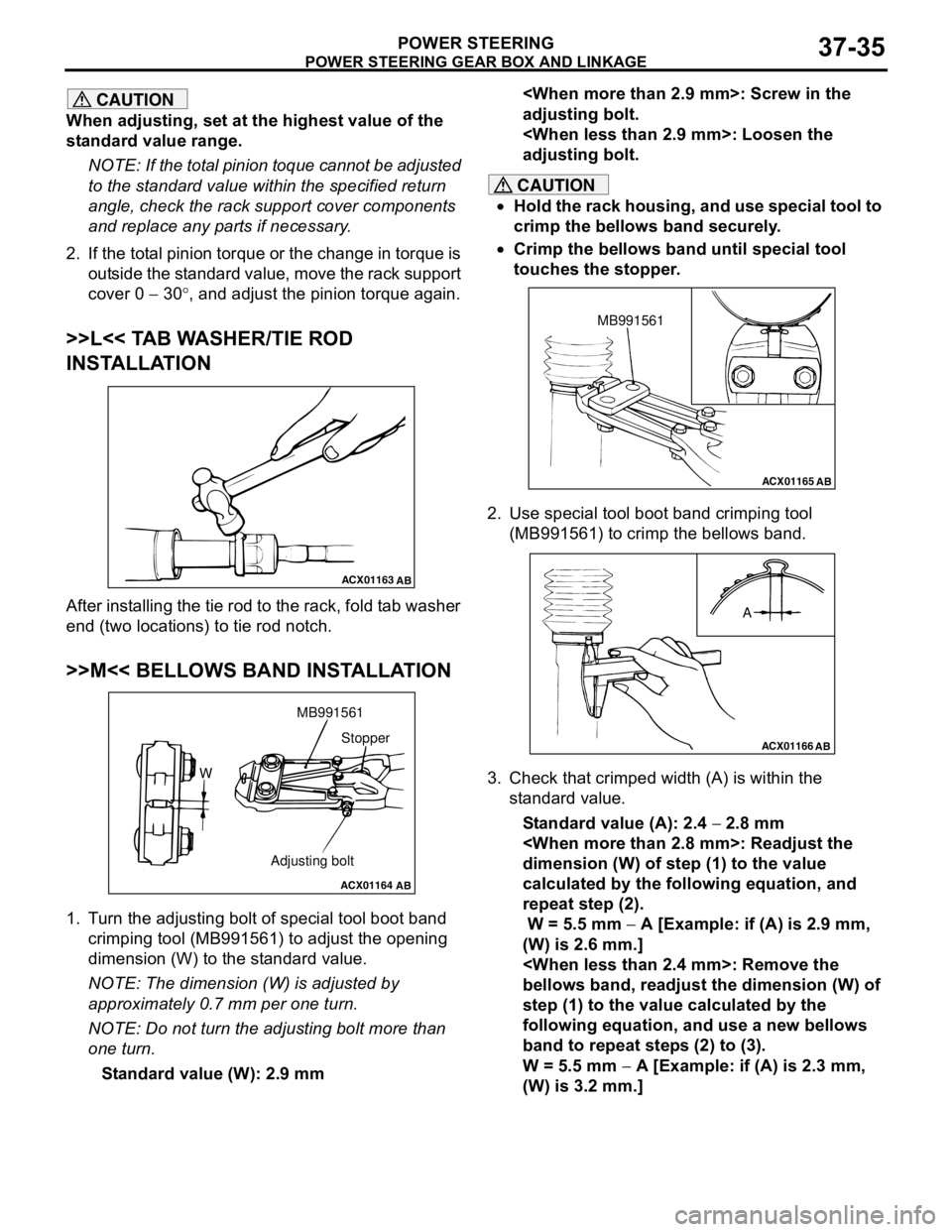
1. Turn the adjusting bolt of special tool boot band
crimping tool (MB991561) to adjust the opening
dimension (W) to the standard value.
NOTE: The dimension (W) is adjusted by
approximately 0.7 mm per one turn.
NOTE: Do not turn the adjusting bolt more than
one turn.
Standard value (W): 2.9 mm
adjusting bolt.
adjusting bolt.
CAUTION
•Hold the rack housing, and use special tool to
crimp the bellows band securely.
•Crimp the bellows band until special tool
touches the stopper.
2. Use special tool boot band crimping tool
(MB991561) to crimp the bellows band.
3. Check that crimped width (A) is within the
standard value.
Standard value (A): 2.4 − 2.8 mm
dimension (W) of step (1) to the value
calculated by the following equation, and
repeat step (2).
W = 5.5 mm − A [Example: if (A) is 2.9 mm,
(W) is 2.6 mm.]
bellows band, readjust the dimension (W) of
step (1) to the value calculated by the
following equation, and use a new bellows
band to repeat steps (2) to (3).
W = 5.5 mm − A [Example: if (A) is 2.3 mm,
(W) is 3.2 mm.]
ACX01163
AB
ACX01164
AB
WMB991561
Adjusting boltStopper
ACX01165AB
MB991561
ACX01166
AB
A
Page 270 of 788
POWER STEERING GEAR BOX AND LINKAGE
POWER STEERING37-36
>>N<< TIE ROD END/LOCK NUT
INSTALLATION
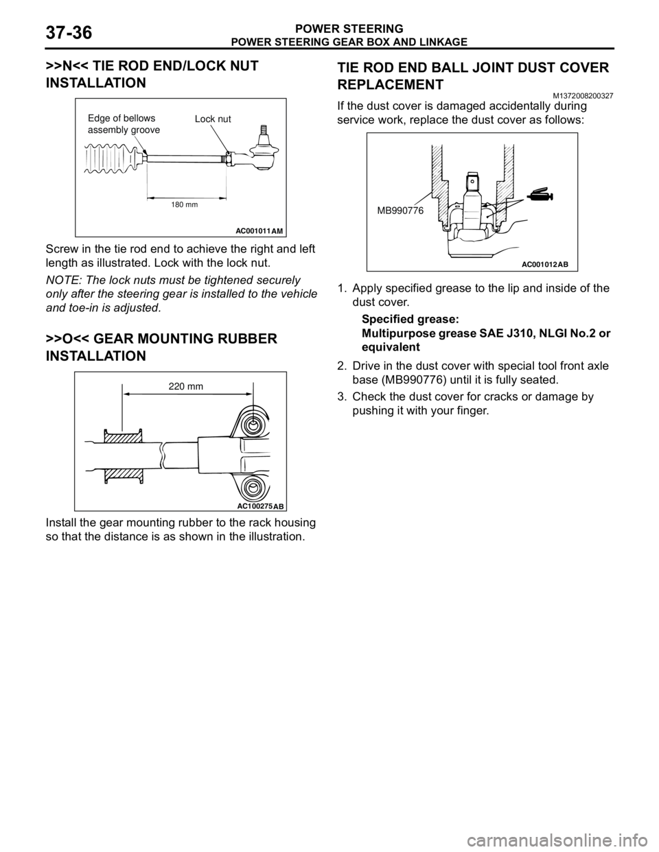
Screw in the tie rod end to achieve the right and left
length as illustrated. Lock with the lock nut.
NOTE: The lock nuts must be tightened securely
only after the steering gear is installed to the vehicle
and toe-in is adjusted.
>>O<< GEAR MOUNTING RUBBER
INSTALLATION
Install the gear mounting rubber to the rack housing
so that the distance is as shown in the illustration.
TIE ROD END BALL JOINT DUST COVER
REPLACEMENT
M1372008200327
If the dust cover is damaged accidentally during
service work, replace the dust cover as follows:
1. Apply specified grease to the lip and inside of the
dust cover.
Specified grease:
Multipurpose grease SAE J310, NLGI No.2 or
equivalent
2. Drive in the dust cover with special tool front axle
base (MB990776) until it is fully seated.
3. Check the dust cover for cracks or damage by
pushing it with your finger.
AC001011
AM
Lock nut Edge of bellows
assembly groove
180 mm
AC100275
AB
220 mm
AC001012
AB
MB990776
Page 271 of 788
POWER STEERING OIL PUMP ASSEMBLY
POWER STEERING37-37
POWER STEERING OIL PUMP ASSEMBLY
REMOVAL AND INSTALLATIONM1372005200298
<1300, 1600>
Pre-removal Operation
•Power Steering Fluid Draining (Refer to P.37-13).Post-installation Operation
•Power Steering Fluid Supplying and Bleeding (Refer to
P.37-13).
•Drive Belt Tension Check (1300, 1600: refer to GROUP
11A, On-vehicle Service − Drive Belt Tension Check
P.11A-7/2000: refer to GROUP 11C, On-vehicle Service −
Drive Belt Tension Check P.11C-7).
AC209708
87
12 34
5
6
57 ± 7 N·m
40 ± 4 N·m 22 ± 4 N·m
N
9
40 ± 5 N·m
AC
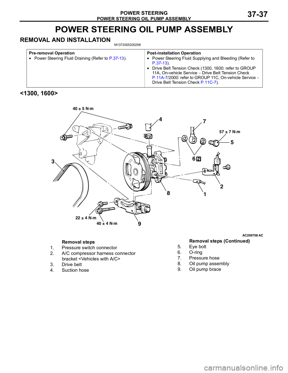
Removal steps
1. Pressure switch connector
2. A/C compressor harness connector
bracket
3. Drive belt
4. Suction hose5. Eye bolt
6. O-ring
7. Pressure hose
8. Oil pump assembly
9. Oil pump braceRemoval steps (Continued)
Page 272 of 788
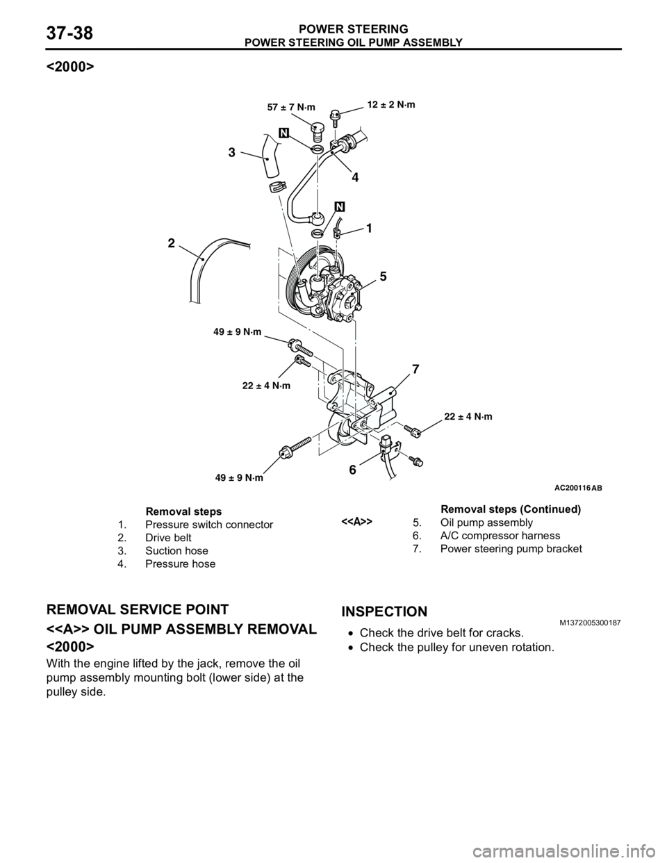
POWER STEERING OIL PUMP ASSEMBLY
POWER STEERING37-38
<2000>
REMOVAL SERVICE POINT
<> OIL PUMP ASSEMBLY REMOVAL
<2000>
With the engine lifted by the jack, remove the oil
pump assembly mounting bolt (lower side) at the
pulley side.
INSPECTIONM1372005300187
•Check the drive belt for cracks.
•Check the pulley for uneven rotation.
AC200116
AB
22 ± 4 N·m 12 ± 2 N·m
22 ± 4 N·m 49 ± 9 N·m57 ± 7 N·m
1
5 4 3
6 2
7
49 ± 9 N·m
Removal steps
1. Pressure switch connector
2. Drive belt
3. Suction hose
4. Pressure hose<>5. Oil pump assembly
6. A/C compressor harness
7. Power steering pump bracketRemoval steps (Continued)
Page 275 of 788
POWER STEERING OIL PUMP ASSEMBLY
POWER STEERING37-41
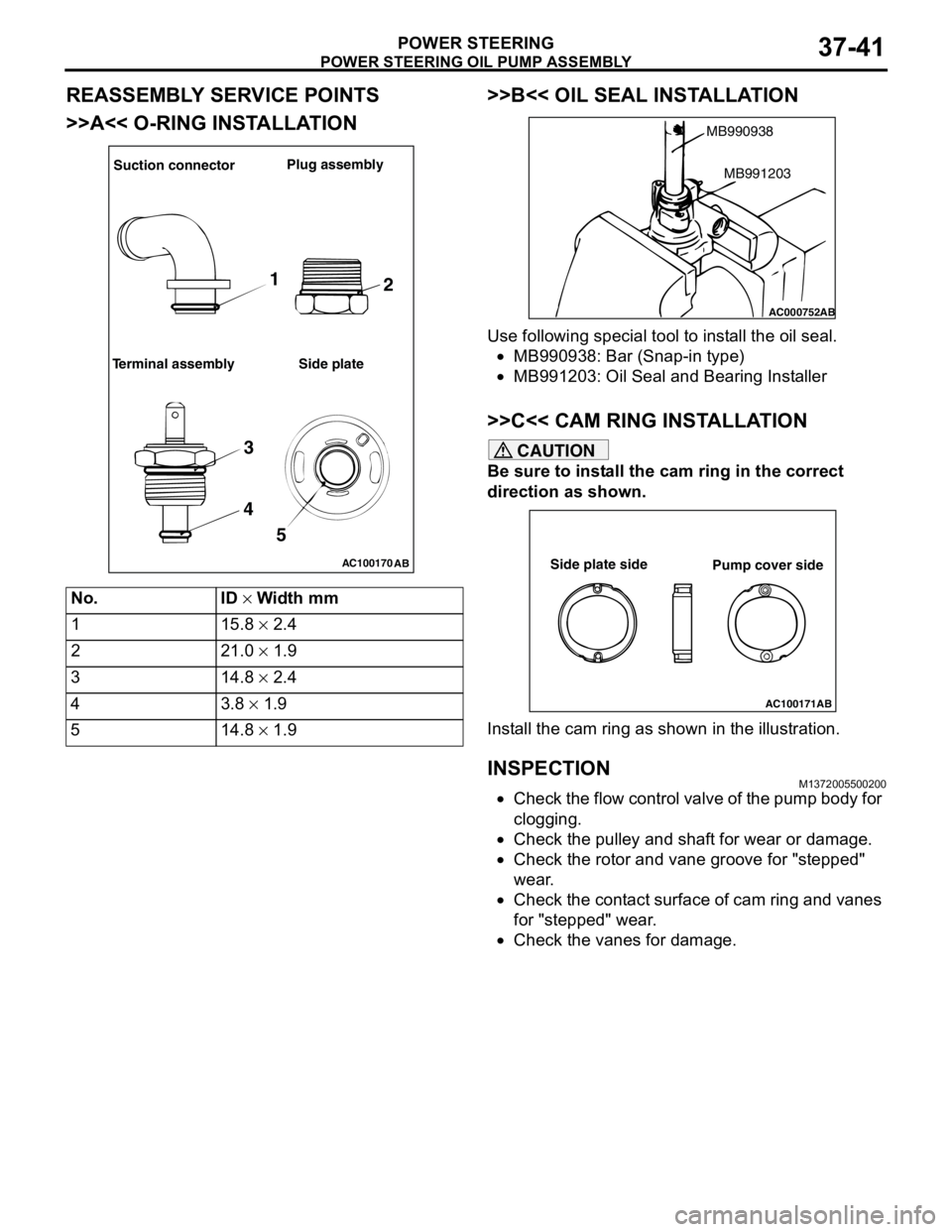
REASSEMBLY SERVICE POINTS
>>A<< O-RING INSTALLATION>>B<< OIL SEAL INSTALLATION
Use following special tool to install the oil seal.
•MB990938: Bar (Snap-in type)
•MB991203: Oil Seal and Bearing Installer
>>C<< CAM RING INSTALLATION
CAUTION
Be sure to install the cam ring in the correct
direction as shown.
Install the cam ring as shown in the illustration.
INSPECTIONM1372005500200
•Check the flow control valve of the pump body for
clogging.
•Check the pulley and shaft for wear or damage.
•Check the rotor and vane groove for "stepped"
wear.
•Check the contact surface of cam ring and vanes
for "stepped" wear.
•Check the vanes for damage. No. ID × Width mm
1 15.8 × 2.4
2 21.0 × 1.9
3 14.8 × 2.4
43.8 × 1.9
5 14.8 × 1.9
AC100170
AB
Suction connectorPlug assembly
Terminal assembly Side plate
1
2
3
4
5
AC000752
MB990938
AB
MB991203
AC100171AB
Side plate side
Pump cover side
Page 280 of 788
42-2
TROUBLESHOOTING . . . . . . . . . .42-26
ON-VEHICLE SERVICE. . . . . . . . .42-27
DOOR FIT ADJUSTMENT. . . . . . . . . . . 42-27
DOOR WINDOW GLASS ADJUSTMENT42-28
GLASS SLIDING MECHANISM CHECK
AND ADJUSTMENT . . . . . . . . . . . . . . . 42-28
POWER WINDOW OPERATING
CURRENT CHECK . . . . . . . . . . . . . . . . 42-28
POWER WINDOW RELAY CHECK . . . 42-29
CIRCUIT BREAKER (INCORPORATED
IN THE POWER WINDOW MOTOR)
INSPECTION . . . . . . . . . . . . . . . . . . . . . 42-29
POWER WINDOW CHECK . . . . . . . . . . 42-29
CENTRAL DOOR LOCKING SYSTEM
INSPECTION . . . . . . . . . . . . . . . . . . . . . 42-29
DOOR OUTSIDE HANDLE PLAY
CHECK . . . . . . . . . . . . . . . . . . . . . . . . . 42-29
DOOR INSIDE HANDLE PLAY
ADJUSTMENT . . . . . . . . . . . . . . . . . . . . 42-30
DOOR ASSEMBLY . . . . . . . . . . . .42-31
REMOVAL AND INSTALLATION . . . . . 42-31
INSPECTION . . . . . . . . . . . . . . . . . . . . . 42-32
DOOR GLASS AND
REGULATOR . . . . . . . . . . . . . . . . .
42-32
REMOVAL AND INSTALLATION . . . . . 42-32
INSPECTION . . . . . . . . . . . . . . . . . . . . . 42-34
DOOR HANDLE AND LATCH . . . .42-36
REMOVAL AND INSTALLATION . . . . . 42-36
INSPECTION . . . . . . . . . . . . . . . . . . . . . 42-37
WINDOW GLASS RUNCHANNEL AND
DOOR OPENING
WEATHERSTRIP . . . . . . . . . . . . . .
42-39
REMOVAL AND INSTALLATION . . . . . 42-39
TRUNK LID . . . . . . . . . . . . . . . .42-41
SPECIAL TOOL . . . . . . . . . . . . . . .
42-41
ON-VEHICLE SERVICE. . . . . . . . .42-41
TRUNK LID ADJUSTMENT . . . . . . . . . . 42-41
ADJUSTMENT OF CLEARANCE
AROUND TRUNK LID . . . . . . . . . . . . . . 42-42
TRUNK LID STRIKER ADJUSTMENT . 42-42
TRUNK LID HEIGHT ADJUSTMENT . . 42-42
TRUNK LID . . . . . . . . . . . . . . . . . . .42-43
REMOVAL AND INSTALLATION . . . . . . 42-43
INSPECTION . . . . . . . . . . . . . . . . . . . . . 42-45
TAILGATE . . . . . . . . . . . . . . . . 42-46
SERVICE SPECIFICATIONS . . . . .
42-46
SEALANTS . . . . . . . . . . . . . . . . . . .42-46
SPECIAL TOOL . . . . . . . . . . . . . . .42-46
TROUBLESHOOTING . . . . . . . . . .42-46
ON-VEHICLE SERVICE . . . . . . . . .42-46
TAILGATE FIT ADJUSTMENT. . . . . . . . 42-46
TAILGATE HANDLE PLAY CHECK . . . . 42-47
TAILGATE . . . . . . . . . . . . . . . . . . .42-48
REMOVAL AND INSTALLATION . . . . . . 42-48
TAILGATE HANDLE AND
LATCH . . . . . . . . . . . . . . . . . . . . . .
42-50
REMOVAL AND INSTALLATION . . . . . . 42-50
INSPECTION . . . . . . . . . . . . . . . . . . . . . 42-51
KEYLESS ENTRY SYSTEM . . 42-51
SERVICE SPECIFICATIONS . . . . .
42-51
SPECIAL TOOLS . . . . . . . . . . . . . .42-52
TROUBLESHOOTING . . . . . . . . . .42-53
ON-VEHICLE SERVICE . . . . . . . . .42-53
KEYLESS ENTRY SYSTEM CHECK. . . 42-53
KEYLESS ENTRY SYSTEM TIMER
LOCK FUNCTION INSPECTION . . . . . . 42-53
ENABLING/DISABLING
THE ANSWERBACK FUNCTION . . . . . 42-53
HOW TO REGISTER SECRET CODE . 42-55
TRANSMITTER. . . . . . . . . . . . . . . .42-58
DISASSEMBLY AND REASSEMBLY . . 42-58
INSPECTION . . . . . . . . . . . . . . . . . . . . . 42-59
Page 289 of 788
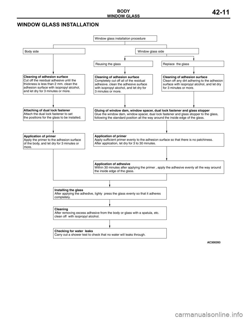
WINDOW GLASS
BODY42-11
WINDOW GLASS INSTALLATION
Cleaning of adhesion surface
Cut off the residual adhesive until the
thickness is less than 2 mm. clean the
adhesion surface with isopropyl alcohol,
and let dry for 3 minutes or more.Cleaning of adhesion surface
Completely cut off all of the residual
adhesive. clean the adhesive surface
with isopropyl alcohol, and let dry for
3 minutes or more.Cleaning of adhesion surface
Clean off any dirt adhering to the adhesion
surface with isopropyl alcohol, and let dry
for 3 minutes or more.
Attaching of dual lock fastener
Attach the dual lock fastener to set
the positions for the glass to be installed.
Gluing of window dam, window spacer, dual lock fastener and glass stopper
Glue the window dam, window spacer, dual lock fastener and glass stopper to the glass,
following the standard position all the way around the inside edge of the glass.
Application of primer
Apply the primer to the adhesion surface
of the body, and let dry for 3 minutes or
more.Application of primer
Apply sufficient primer evenly to the adhesion surface so that there is no patchiness.
After application, let dry for 3 to 30 minutes.
Application of adhesive
Within 30 minutes after applying the primer , apply the adhesive evenly all the way around
the inside edge of the glass.
Installing the glass
After applying the adhedive, lighty press the glass evenly so that it adheres
completely.
Cleaning
After removing excess adhesive from the body or glass with a spatula, etc.
clean off with isopropyl alcohol.
Checking for water leaks
Carry out a shower test to check that no water will leaks through.Replace the glass
Reusing the glass
Window glass installation procedure
Body side
Window glass side
AC300393
Page 304 of 788
DOOR
BODY42-26
TROUBLESHOOTINGM1423000700312
The door system is controlled by the Smart Wiring
System (SWS). For troubleshooting, refer to GROUP
54B, Troubleshooting P.54B-17 or GROUP 54C,
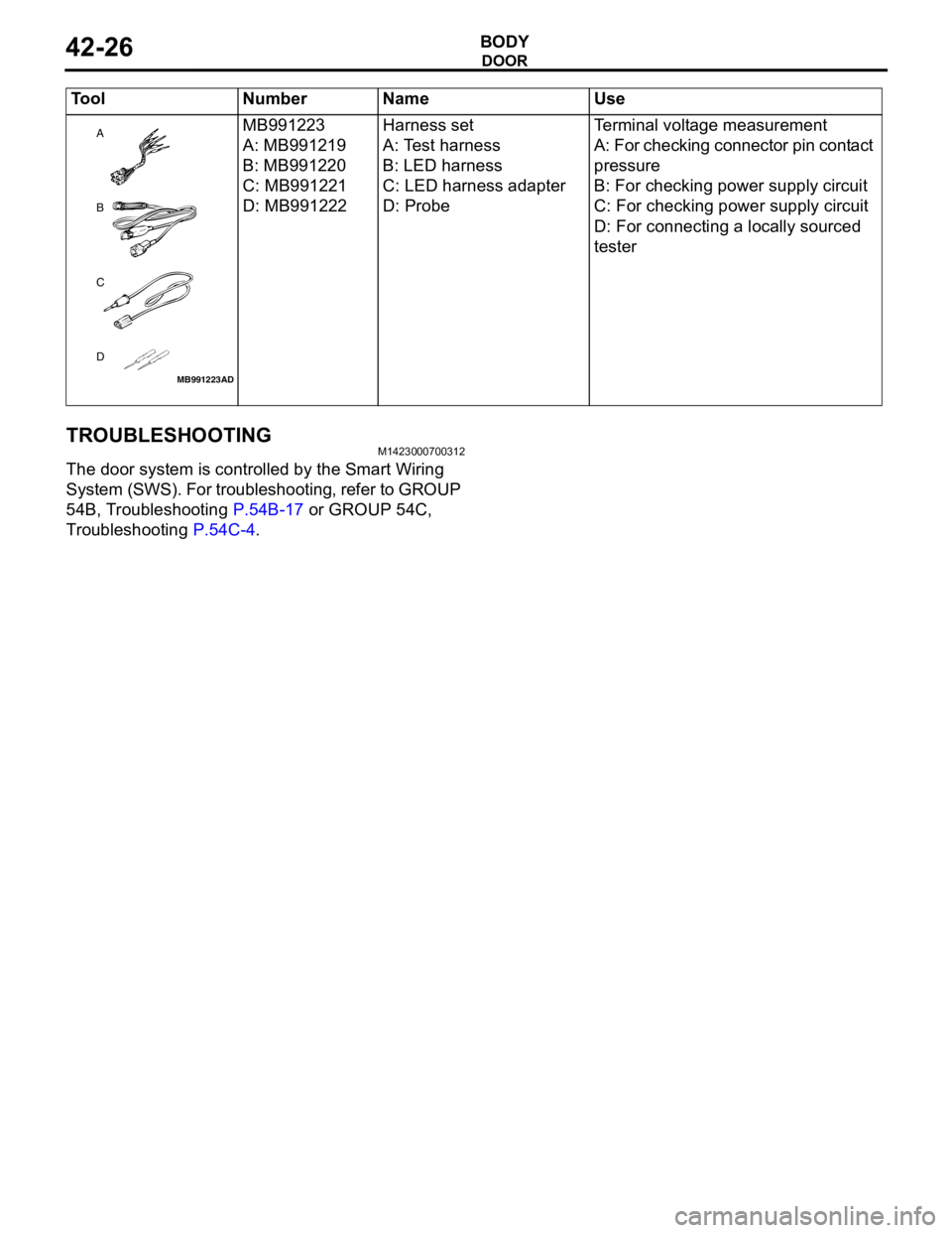
Troubleshooting P.54C-4. MB991223
A: MB991219
B: MB991220
C: MB991221
D: MB991222Harness set
A: Test harness
B: LED harness
C: LED harness adapter
D: ProbeTerminal voltage measurement
A: For checking connector pin contact
pressure
B: For checking power supply circuit
C: For checking power supply circuit
D: For connecting a locally sourced
tester Tool Number Name Use
MB991223
A
D C
B
AD
Page 306 of 788
DOOR
BODY42-28
DOOR WINDOW GLASS ADJUSTMENTM1423001000327
Check that the door glass moves while contacting
the door glass channel when it is raised and lowered
fully. If not, adjust the door window according to the
following procedures.
1. Remove the door trim assembly (Refer to GROUP
52A, Door trim P.52A-15).
2. Remove the waterproof film (Refer to P.42-39).
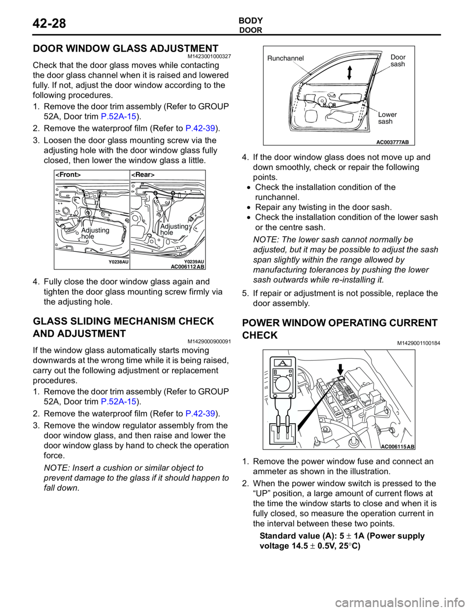
3. Loosen the door glass mounting screw via the
adjusting hole with the door window glass fully
closed, then lower the window glass a little.
4. Fully close the door window glass again and
tighten the door glass mounting screw firmly via
the adjusting hole.
GLASS SLIDING MECHANISM CHECK
AND ADJUSTMENT
M1429000900091
If the window glass automatically starts moving
downwards at the wrong time while it is being raised,
carry out the following adjustment or replacement
procedures.
1. Remove the door trim assembly (Refer to GROUP
52A, Door trim P.52A-15).
2. Remove the waterproof film (Refer to P.42-39).
3. Remove the window regulator assembly from the
door window glass, and then raise and lower the
door window glass by hand to check the operation
force.
NOTE: Insert a cushion or similar object to
prevent damage to the glass if it should happen to
fall down.4. If the door window glass does not move up and
down smoothly, check or repair the following
points.
•Check the installation condition of the
runchannel.
•Repair any twisting in the door sash.
•Check the installation condition of the lower sash
or the centre sash.
NOTE: The lower sash cannot normally be
adjusted, but it may be possible to adjust the sash
span slightly within the range allowed by
manufacturing tolerances by pushing the lower
sash outwards while re-installing it.
5. If repair or adjustment is not possible, replace the
door assembly.
POWER WINDOW OPERATING CURRENT
CHECK
M1429001100184
1. Remove the power window fuse and connect an
ammeter as shown in the illustration.
2. When the power window switch is pressed to the
“UP” position, a large amount of current flows at
the time the window starts to close and when it is
fully closed, so measure the operation current in
the interval between these two points.
Standard value (A): 5 ± 1A (Power supply
voltage 14.5 ± 0.5V, 25°C)
Y0238AUY0239AUAC006112
AB
Adjusting
holeAdjusting
hole
AC003777
RunchannelDoor
sash
Lower
sash
AB
AC006115AB