check MITSUBISHI LANCER 2005 Workshop Manual
[x] Cancel search | Manufacturer: MITSUBISHI, Model Year: 2005, Model line: LANCER, Model: MITSUBISHI LANCER 2005Pages: 788, PDF Size: 45.98 MB
Page 221 of 788
STABILIZER BAR
REAR SUSPENSION34-21
INSTALLATION SERVICE POINTS
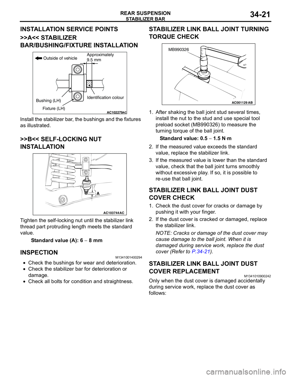
>>A<< STABILIZER
BAR/BUSHING/FIXTURE INSTALLATION
Install the stabilizer bar, the bushings and the fixtures
as illustrated.
>>B<< SELF-LOCKING NUT
INSTALLATION
Tighten the self-locking nut until the stabilizer link
thread part protruding length meets the standard
value.
Standard value (A): 6 − 8 mm
INSPECTIONM1341001400294
•Check the bushings for wear and deterioration.
•Check the stabilizer bar for deterioration or
damage.
•Check all bolts for condition and straightness.
STABILIZER LINK BALL JOINT TURNING
TORQUE CHECK
1. After shaking the ball joint stud several times,
install the nut to the stud and use special tool
preload socket (MB990326) to measure the
turning torque of the ball joint.
Standard value: 0.5 − 1.5 N⋅m
2. If the measured value exceeds the standard
value, replace the stabilizer link.
3. If the measured value is lower than the standard
value, check that the ball joint turns smoothly
without excessive play. If so, it is possible to
re-use that ball joint.
STABILIZER LINK BALL JOINT DUST
COVER CHECK
1. Check the dust cover for cracks or damage by
pushing it with your finger.
2. If the dust cover is cracked or damaged, replace
the stabilizer link.
NOTE: Cracks or damage of the dust cover may
cause damage to the ball joint. When it is
damaged during service work, replace the dust
cover (Refer to P.34-21).
STABILIZER LINK BALL JOINT DUST
COVER REPLACEMENT
M1341010900242
Only when the dust cover is damaged accidentally
during service work, replace the dust cover as
follows:
AC102279AC
Outside of vehicle
Bushing (LH)
Fixture (LH)Identification colourApproximately
9.5 mm
AC103744
A
AC
AC001129
MB990326
AB
Page 222 of 788
STABILIZER BAR
REAR SUSPENSION34-22
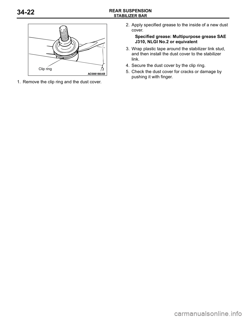
1. Remove the clip ring and the dust cover.2. Apply specified grease to the inside of a new dust
cover.
Specified grease: Multipurpose grease SAE
J310, NLGI No.2 or equivalent
3. Wrap plastic tape around the stabilizer link stud,
and then install the dust cover to the stabilizer
link.
4. Secure the dust cover by the clip ring.
5. Check the dust cover for cracks or damage by
pushing it with finger.
AC006188 AB
Clip ring
Page 225 of 788
36-1
GROUP 36
PARKING BRAKES
CONTENTS
GENERAL INFORMATION . . . . . . . .36-2
SERVICE SPECIFICATIONS . . . . . . .36-2
LUBRICANTS . . . . . . . . . . . . . . . . . .36-3
ON-VEHICLE SERVICE . . . . . . . . . . .36-3
PARKING BRAKE LEVER STROKE
CHECK AND ADJUSTMENT . . . . . . . . . . . 36-3
LINING RUNNING-IN . . . . . . . . . . . . . . . . . 36-3
PARKING BRAKE SWITCH CHECK . . . . . 36-4
PARKING BRAKE LEVER . . . . . . . . .36-5
REMOVAL AND INSTALLATION . . . . . . . . 36-5
PARKING BRAKE CABLE . . . . . . . . .36-6
REMOVAL AND INSTALLATION . . . . . . . . 36-6
PARKING BRAKE LINING AND
DRUM . . . . . . . . . . . . . . . . . . . . . . . . .36-7
REMOVAL AND INSTALLATION . . . . . . . . 36-7
INSPECTION . . . . . . . . . . . . . . . . . . . . . . . . 36-9
Page 227 of 788
LUBRICANTS
PARKING BRAKES36-3
LUBRICANTS
M1361000400293
ON-VEHICLE SERVICE
PARKING BRAKE LEVER STROKE
CHECK AND ADJUSTMENT
M1361000900339
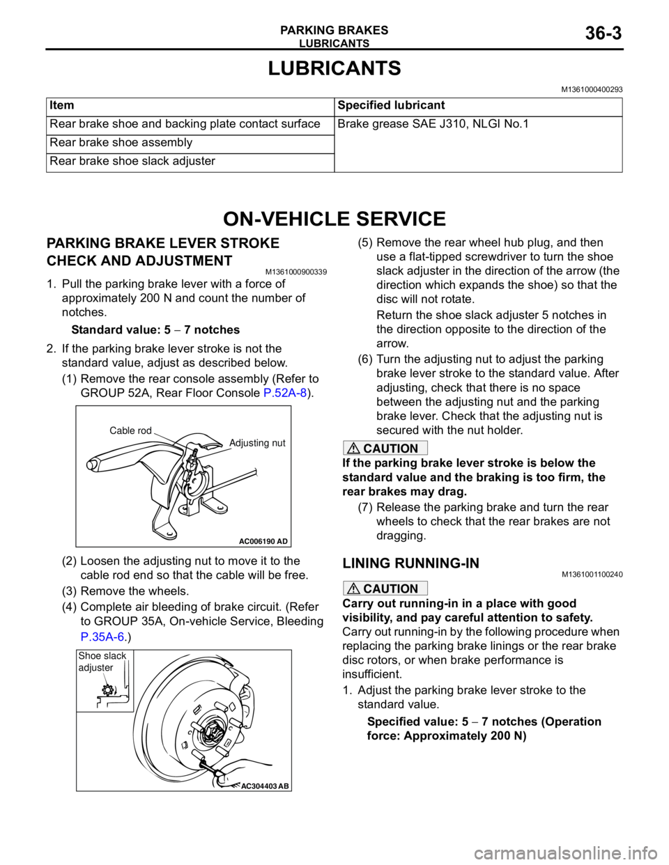
1. Pull the parking brake lever with a force of
approximately 200 N and count the number of
notches.
Standard value: 5 − 7 notches
2. If the parking brake lever stroke is not the
standard value, adjust as described below.
(1) Remove the rear console assembly (Refer to
GROUP 52A, Rear Floor Console P.52A-8).
(2) Loosen the adjusting nut to move it to the
cable rod end so that the cable will be free.
(3) Remove the wheels.
(4) Complete air bleeding of brake circuit. (Refer
to GROUP 35A, On-vehicle Service, Bleeding
P.35A-6.)(5) Remove the rear wheel hub plug, and then
use a flat-tipped screwdriver to turn the shoe
slack adjuster in the direction of the arrow (the
direction which expands the shoe) so that the
disc will not rotate.
Return the shoe slack adjuster 5 notches in
the direction opposite to the direction of the
arrow.
(6) Turn the adjusting nut to adjust the parking
brake lever stroke to the standard value. After
adjusting, check that there is no space
between the adjusting nut and the parking
brake lever. Check that the adjusting nut is
secured with the nut holder.
CAUTION
If the parking brake lever stroke is below the
standard value and the braking is too firm, the
rear brakes may drag.
(7) Release the parking brake and turn the rear
wheels to check that the rear brakes are not
dragging.
LINING RUNNING-INM1361001100240
CAUTION
Carry out running-in in a place with good
visibility, and pay careful attention to safety.
Carry out running-in by the following procedure when
replacing the parking brake linings or the rear brake
disc rotors, or when brake performance is
insufficient.
1. Adjust the parking brake lever stroke to the
standard value.
Specified value: 5 − 7 notches (Operation
force: Approximately 200 N) Item Specified lubricant
Rear brake shoe and backing plate contact surface Brake grease SAE J310, NLGI No.1
Rear brake shoe assembly
Rear brake shoe slack adjuster
AC006190
Cable rod
Adjusting nut
AD
AC304403AB
Shoe slack
adjuster
Page 228 of 788
ON-VEHICLE SERVICE
PARKING BRAKES36-4
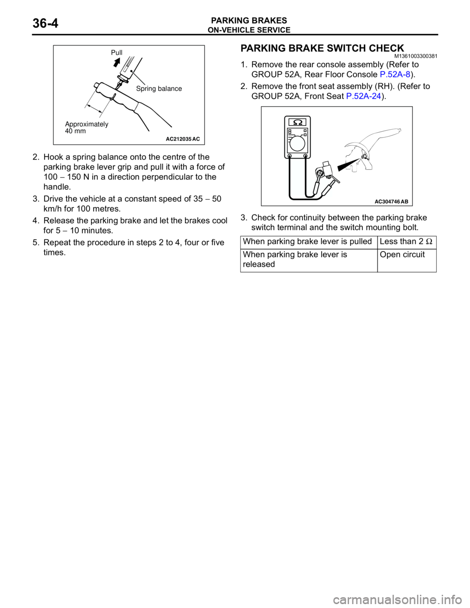
2. Hook a spring balance onto the centre of the
parking brake lever grip and pull it with a force of
100 − 150 N in a direction perpendicular to the
handle.
3. Drive the vehicle at a constant speed of 35 − 50
km/h for 100 metres.
4. Release the parking brake and let the brakes cool
for 5 − 10 minutes.
5. Repeat the procedure in steps 2 to 4, four or five
times.
PARKING BRAKE SWITCH CHECKM1361003300381
1. Remove the rear console assembly (Refer to
GROUP 52A, Rear Floor Console P.52A-8).
2. Remove the front seat assembly (RH). (Refer to
GROUP 52A, Front Seat P.52A-24).
3. Check for continuity between the parking brake
switch terminal and the switch mounting bolt.
AC212035AC
Spring balance
Approximately
40 mmPull
When parking brake lever is pulled Less than 2 Ω
When parking brake lever is
releasedOpen circuit
AC304746AB
Page 231 of 788
PARKING BRAKE LINING AND DRUM
PARKING BRAKES36-7
PARKING BRAKE LINING AND DRUM
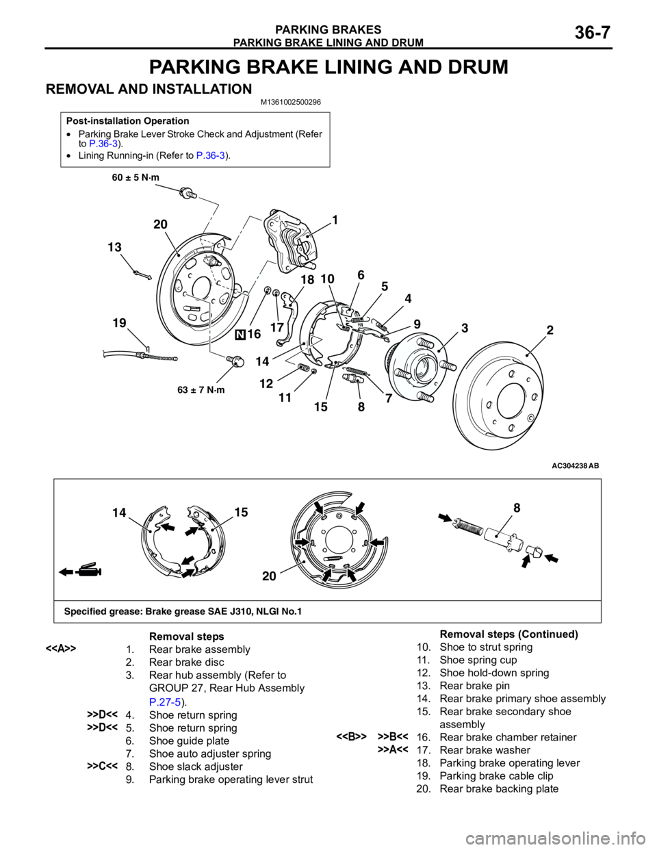
REMOVAL AND INSTALLATIONM1361002500296
Post-installation Operation
•Parking Brake Lever Stroke Check and Adjustment (Refer
to P.36-3).
•Lining Running-in (Refer to P.36-3).
AC304238
19
60 ± 5 N·m
63 ± 7 N·m
AB
13
4
155
3
89
72 1
6
10
11 121718
14 16 20
N
15
14
208
Specified grease: Brake grease SAE J310, NLGI No.1
Removal steps
<>
1. Rear brake assembly
2. Rear brake disc
3. Rear hub assembly (Refer to
GROUP 27, Rear Hub Assembly
P.27-5).
>>D<<4. Shoe return spring
>>D<<5. Shoe return spring
6. Shoe guide plate
7. Shoe auto adjuster spring
>>C<<8. Shoe slack adjuster
9. Parking brake operating lever strut
10. Shoe to strut spring
11. Shoe spring cup
12. Shoe hold-down spring
13. Rear brake pin
14. Rear brake primary shoe assembly
15. Rear brake secondary shoe
assembly
<> >>B<<16. Rear brake chamber retainer
>>A<<17. Rear brake washer
18. Parking brake operating lever
19. Parking brake cable clip
20. Rear brake backing plate
Removal steps (Continued)
Page 233 of 788
PARKING BRAKE LINING AND DRUM
PARKING BRAKES36-9
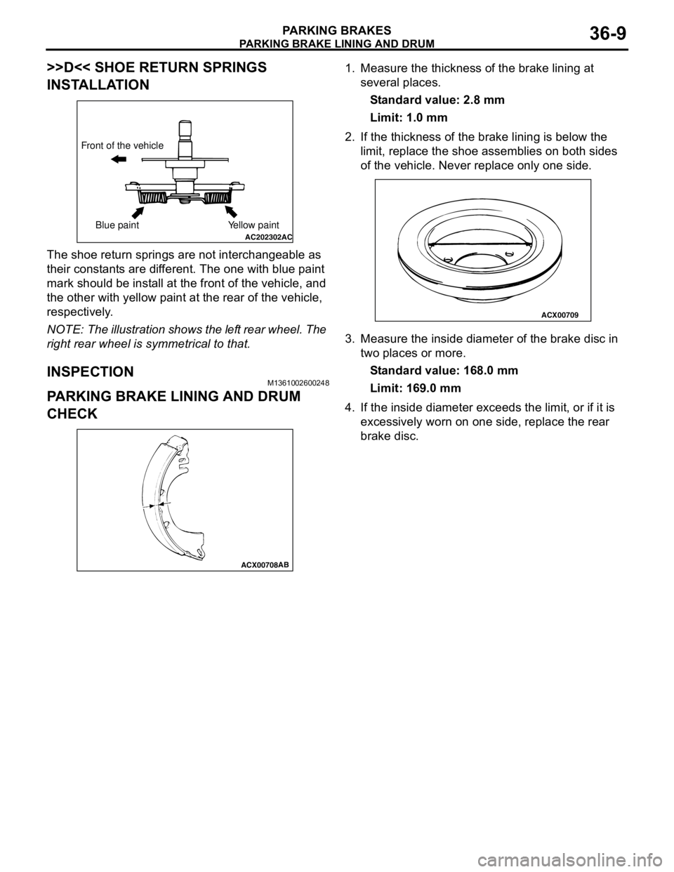
>>D<< SHOE RETURN SPRINGS
INSTALLATION
The shoe return springs are not interchangeable as
their constants are different. The one with blue paint
mark should be install at the front of the vehicle, and
the other with yellow paint at the rear of the vehicle,
respectively.
NOTE: The illustration shows the left rear wheel. The
right rear wheel is symmetrical to that.
INSPECTIONM1361002600248
PARKING BRAKE LINING AND DRUM
CHECK
1. Measure the thickness of the brake lining at
several places.
Standard value: 2.8 mm
Limit: 1.0 mm
2. If the thickness of the brake lining is below the
limit, replace the shoe assemblies on both sides
of the vehicle. Never replace only one side.
3. Measure the inside diameter of the brake disc in
two places or more.
Standard value: 168.0 mm
Limit: 169.0 mm
4. If the inside diameter exceeds the limit, or if it is
excessively worn on one side, replace the rear
brake disc.
AC202302AC
Front of the vehicle
Blue paint Yellow paint
ACX00708AB
ACX00709
Page 235 of 788
37-1
GROUP 37
POWER STEERING
CONTENTS
GENERAL INFORMATION . . . . . . . .37-3
SERVICE SPECIFICATIONS . . . . . . .37-6
LUBRICANTS . . . . . . . . . . . . . . . . . .37-7
SEALANTS . . . . . . . . . . . . . . . . . . . .37-7
SPECIAL TOOLS . . . . . . . . . . . . . . . .37-8
ON-VEHICLE SERVICE . . . . . . . . . . .37-11
STEERING WHEEL FREE PLAY
CHECK . . . . . . . . . . . . . . . . . . . . . . . . . . . . 37-11
STEERING ANGLE CHECK . . . . . . . . . . . . 37-11
TIE ROD END BALL JOINT TURNING
TORQUE CHECK . . . . . . . . . . . . . . . . . . . . 37-12
STATIONARY STEERING EFFORT
CHECK . . . . . . . . . . . . . . . . . . . . . . . . . . . . 37-12
STEERING WHEEL RETURN TO
CENTRE CHECK . . . . . . . . . . . . . . . . . . . . 37-13DRIVE BELT TENSION CHECK . . . . . . . . . 37-13
FLUID LEVEL CHECK . . . . . . . . . . . . . . . . 37-13
FLUID REPLACEMENT . . . . . . . . . . . . . . . 37-13
POWER STEERING SYSTEM AIR
BLEEDING . . . . . . . . . . . . . . . . . . . . . . . . . 37-13
OIL PUMP PRESSURE TEST . . . . . . . . . . 37-14
POWER STEERING PRESSURE
SWITCH CHECK . . . . . . . . . . . . . . . . . . . . . 37-15
TIE ROD END BALL JOINT DUST COVER
CHECK . . . . . . . . . . . . . . . . . . . . . . . . . . . . 37-15
STEERING COLUMN SHAFT
ASSEMBLY SHOCK ABSORBING
MECHANISM CHECK . . . . . . . . . . . . . . . . . 37-15
STEERING WHEEL* . . . . . . . . . . . . . .37-17
REMOVAL AND INSTALLATION
REMOVAL AND INSTALLATION
Continued on next page
WARNINGS REGARDING SERVICING OF SUPPLEMENTAL RESTRAINT SYSTEM (SRS) EQUIPPED VEHICLES
WARNING
•Improper service or maintenance of any component of the SRS, or any SRS-related component, can lead to
personal injury or death to service personnel (from inadvertent firing of the air bag) or to the driver and
paassenger (from rendering the SRS inoperative).
•Service or maintenance of any SRS component or SRS-related component must be performed only at an
authorized MITSUBISHI dealer.
•MITSUBISHI dealer personnel must thoroughly review this manual, and especially its GROUP 52B - Supplemental
Restraint System (SRS) before beginning any service or maintenance of any component of the SRS or any
SRS-related component.
NOTE
The SRS includes the following components: SRS air bag control unit, SRS warning light, front impact sensors, air bag module,
clock spring, and interconnecting wiring. Other SRS-related components (that may have to be removed/installed in connection
with SRS service or maintenance) are indicated in the table of contents by an asterisk (*).
Page 237 of 788

GENERAL INFORMATION
POWER STEERING37-3
GENERAL INFORMATION
M1372000100337
Power steering has been adopted in all vehicles to
make the steering system easier to handle.
FEATURES
•A 4-spoke steering wheel is used.
•MOMO leather-wrapped 3-spoke steering wheel
is used.
•A steering column has a shock absorbing
mechanism and a tilt steering mechanism.•Integral-type rack and pinion gear with high
rigidity and excellent response is used.
•A vane type pump with a fluid flow rate control
system which change steering effort according to
the engine speed is used.
•The separate plastic resin oil reservoir is used to
reduce weight and to make the fluid level
checking easier.
SPECIFICATIONS
Item Comfort Sport
Steering
wheelType 4-spoke type MOMO leather-wrapped
3-spoke type
Outside diameter mm 380 365
Maximum number of turns 3.19 2.86
3.08
Steering
columnColumn mechanism Shock absorbing mechanism and Tilt steering mechanism
Power steering type Integral type
Oil pump Type Vane pump
Basic discharge amount cm
3/rev.7.2 <1300, 1600>
8.1 <2000>7.2 <1300, 1600>
8.1 <2000>
Relief pressure MPa 8.8 8.8
Reservoir type Separate type (plastic)
Pressure switch Equipped
Steering
gearType Rack and pinion
Stroke ratio (Rack stroke/Steering
wheel maximum turning radius)45.74 45.74
Rack stroke mm 146 131
141
Page 242 of 788
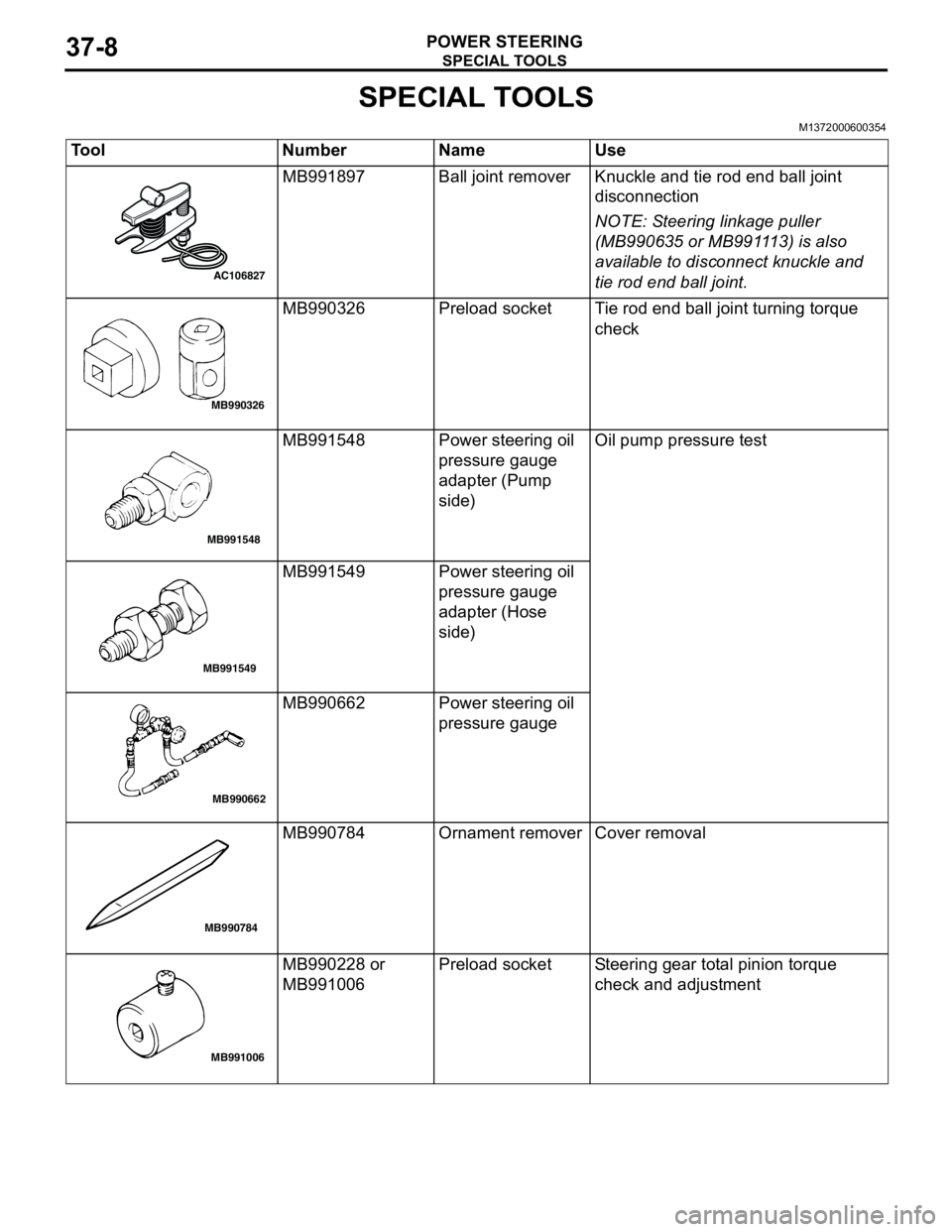
SPECIAL TOOLS
POWER STEERING37-8
SPECIAL TOOLS
M1372000600354
Tool Number Name Use
MB991897 Ball joint remover Knuckle and tie rod end ball joint
disconnection
NOTE: Steering linkage puller
(MB990635 or MB991113) is also
available to disconnect knuckle and
tie rod end ball joint.
MB990326 Preload socket Tie rod end ball joint turning torque
check
MB991548 Power steering oil
pressure gauge
adapter (Pump
side)Oil pump pressure test
MB991549 Power steering oil
pressure gauge
adapter (Hose
side)
MB990662 Power steering oil
pressure gauge
MB990784 Ornament remover Cover removal
MB990228 or
MB991006Preload socket Steering gear total pinion torque
check and adjustment
AC106827
MB990326
MB991548
MB991549
MB990662
MB990784
MB991006