Body MITSUBISHI LANCER 2005 Workshop Manual
[x] Cancel search | Manufacturer: MITSUBISHI, Model Year: 2005, Model line: LANCER, Model: MITSUBISHI LANCER 2005Pages: 788, PDF Size: 45.98 MB
Page 1 of 788
GROUP INDEX
00General . . . . . . . . . . . . . . . . . . . . . . . .
11Engine. . . . . . . . . . . . . . . . . . . . . . . . .
12Engine Lubrication . . . . . . . . . . . . . .
13Fuel . . . . . . . . . . . . . . . . . . . . . . . . . . .
14Engine Cooling . . . . . . . . . . . . . . . . .
15Intake and Exhaust . . . . . . . . . . . . . .
16Engine Electrical . . . . . . . . . . . . . . . .
17Engine and Emission Control . . . . .
21Clutch . . . . . . . . . . . . . . . . . . . . . . . . .
22Manual Transmission . . . . . . . . . . . .
23Automatic Transmission. . . . . . . . . .
26Front Axle . . . . . . . . . . . . . . . . . . . . . .
27Rear Axle . . . . . . . . . . . . . . . . . . . . . .
31Wheel and Tyre . . . . . . . . . . . . . . . . .
32Power Plant Mount . . . . . . . . . . . . . .
33Front Suspension . . . . . . . . . . . . . . .
34Rear Suspension . . . . . . . . . . . . . . . .
35Service Brakes . . . . . . . . . . . . . . . . . .
36Parking Brakes . . . . . . . . . . . . . . . . .
37Power Steering . . . . . . . . . . . . . . . . .
42Body . . . . . . . . . . . . . . . . . . . . . . . . . .
51Exterior . . . . . . . . . . . . . . . . . . . . . . . .
52 . . . . . . . . . .
54Chassis Electrical . . . . . . . . . . . . . . .
55 . . . . . . .
70Component Locations. . . . . . . . . . . .
80Configration Diagrams . . . . . . . . . . .
90Circuit Diagrams . . . . . . . . . . . . . . . .
LANCER /
LANCER WAGON
WORKSHOP MANUAL
FOREWORD
This Workshop manual contains procedures for
service mechanics, including removal, disassembly,
inspection, adjustment, reassembly and installation.
Use the following manuals in combination with this
manual as required.
TECHNICAL INFORMATION MANUAL
PYME0302
PYME0302-A
WORKSHOP MANUAL
CHASSIS GROUP PWME0302
BODY REPAIR MANUAL
PBME0302
PBME0302-A
PARTS CATALOGUE
B606K005A_
All information, illustrations and product descriptions
contained in this manual are current as at the time of
publication. We, however, reserve the right to make
changes at any time without prior notice or obligation.
Mitsubishi Motors Corporation May 2004
Heater, Air Conditioner and
Ventilation Interior and Supplemental
Restraint System (SRS)
Page 21 of 788
TROUBLESHOOTING
ENGINE COOLING14-7
CIRCUIT OPERATION
•The cooling fan motor drive control unit is
powered from fusible link (2).
•The engine-ECU
uses input signals from the A/C switch, the
water temperature sensor unit and the vehicle
speed sensor
sensor to control the speed of the cooling
fan motor (L.H.) and the cooling fan motor (R.H.)
<4G1 (Vehicles with A/C)> or A/C condenser fan
motor <4G6>.
•The engine-ECU
controls the cooling fan motor drive control
unit to activate the cooling fan motor (L.H.) and
the cooling fan motor (R.H.) <4G1 (Vehicles with
A/C)> or A/C condenser fan motor <4G6>.
TECHNICAL DESCRIPTION
•The cause could be a malfunction of the cooling
fan motor drive control unit power supply or earth
circuit.
•If the communication line wiring harness between
the cooling fan motor drive control unit and the
engine-ECU
short-circuited to earth, the cooling fan motor
(L.H.) and the cooling fan motor (R.H.) <4G1
(Vehicles with A/C)> or the A/C condenser fan
motor <4G6> will not rotate.
•The cause could also be a malfunction of the
cooling fan motor (L.H.).
•The cause could also be a malfunction of imput
signal from the A/C switch, the water temperature
sensor unit and the vehicle speed sensor
or the output shaft speed sensor to the
engine-ECU
•The cause could also be a malfunction of the
cooling fan motor drive control unit or the
engine-ECU
TROUBLESHOOTING HINTS
•Malfunction of fusible link (2)
•Malfunction of fan control relay
•Malfunction of cooling fan motor (L.H.)
•Malfunction of cooling fan motor drive control unit
•Malfunction of engine-ECU
engine-A/T-ECU
•Damaged wiring harness or connector
DIAGNOSIS
STEP 1. Check the cooling fan motor (L.H.).
Refer to P.14-25.
Q: Is the cooling fan motor (L.H.) in good condition?
YES :
Go to Step 2 .
NO : Replace the cooling fan motor (L.H.) (Refer
to P.14-35). Then go to Step 24 .
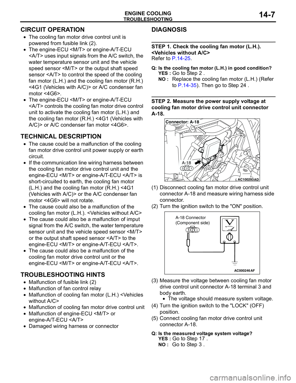
STEP 2. Measure the power supply voltage at
cooling fan motor drive control unit connector
A-18.
(1) Disconnect cooling fan motor drive control unit
connector A-18 and measure wiring harness side
connector.
(2) Turn the ignition switch to the "ON" position.
(3) Measure the voltage between cooling fan motor
drive control unit connector A-18 terminal 3 and
body earth.
•The voltage should measure system voltage.
(4) Turn the ignition switch to the "LOCK" (OFF)
position.
(5) Connect cooling fan motor drive control unit
connector A-18.
Q: Is the measured voltage system voltage?
YES :
Go to Step 17 .
NO : Go to Step 3 .
AC100293
A-18
321
Connector: A-18
AD
AC000246AF
A-18 Connector
(Component side)
Page 22 of 788
TROUBLESHOOTING
ENGINE COOLING14-8
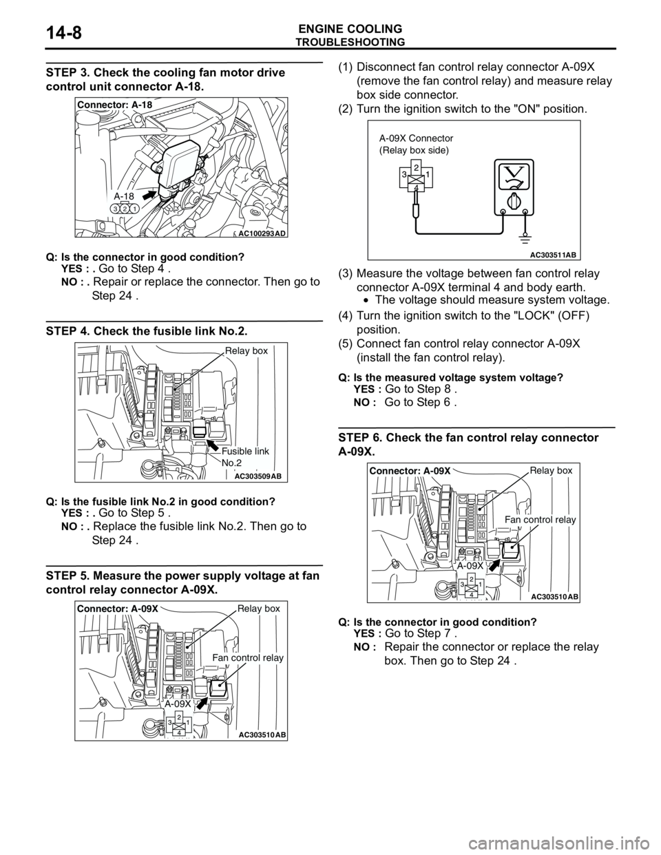
STEP 3. Check the cooling fan motor drive
control unit connector A-18.
Q: Is the connector in good condition?
YES : .
Go to Step 4 .
NO : . Repair or replace the connector. Then go to
Step 24 .
STEP 4. Check the fusible link No.2.
Q: Is the fusible link No.2 in good condition?
YES : .
Go to Step 5 .
NO : . Replace the fusible link No.2. Then go to
Step 24 .
STEP 5. Measure the power supply voltage at fan
control relay connector A-09X.(1) Disconnect fan control relay connector A-09X
(remove the fan control relay) and measure relay
box side connector.
(2) Turn the ignition switch to the "ON" position.
(3) Measure the voltage between fan control relay
connector A-09X terminal 4 and body earth.
•The voltage should measure system voltage.
(4) Turn the ignition switch to the "LOCK" (OFF)
position.
(5) Connect fan control relay connector A-09X
(install the fan control relay).
Q: Is the measured voltage system voltage?
YES :
Go to Step 8 .
NO : Go to Step 6 .
STEP 6. Check the fan control relay connector
A-09X.
Q: Is the connector in good condition?
YES :
Go to Step 7 .
NO : Repair the connector or replace the relay
box. Then go to Step 24 .
AC100293
A-18
321
Connector: A-18
AD
AC303509AB
Fusible link
No.2
Relay box
AC303510AB
Fan control relay
Relay boxConnector: A-09X
A-09X
AC303511AB
A-09X Connector
(Relay box side)
AC303510AB
Fan control relay
Relay boxConnector: A-09X
A-09X
Page 24 of 788
TROUBLESHOOTING
ENGINE COOLING14-10
(3) Measure the voltage between fan control relay
connector A-09X terminal 1 and body earth.
•The voltage should measure system voltage.
(4) Turn the ignition switch to the "LOCK" (OFF)
position.
(5) Connect fan control relay connector A-09X
(install the fan control relay).
Q: Is the measured voltage system voltage?
YES : .
Go to Step 14 .
NO : . Go to Step 12 .
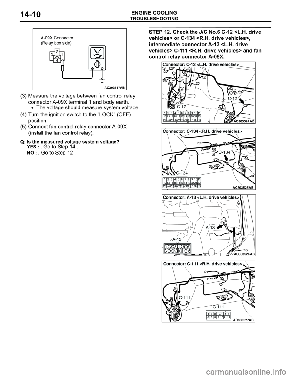
STEP 12. Check the J/C No.6 C-12
intermediate connector A-13
control relay connector A-09X.
AC303517AB
A-09X Connector
(Relay box side)
AC303524
Connector: C-12
AB
C-12
C-12
AC303525
Connector: C-134
AB
C-134
C-134
AC303526
Connector: A-13
AB
A-13
A-13
AC303527
Connector: C-111
AB
C-111
C-111
615
121179
810234
Page 25 of 788
TROUBLESHOOTING
ENGINE COOLING14-11
Q: Are there connectors in good condition?
YES : .
Go to Step 13 .
NO : . Repair or replace the connector. Then go to
Step 24 .
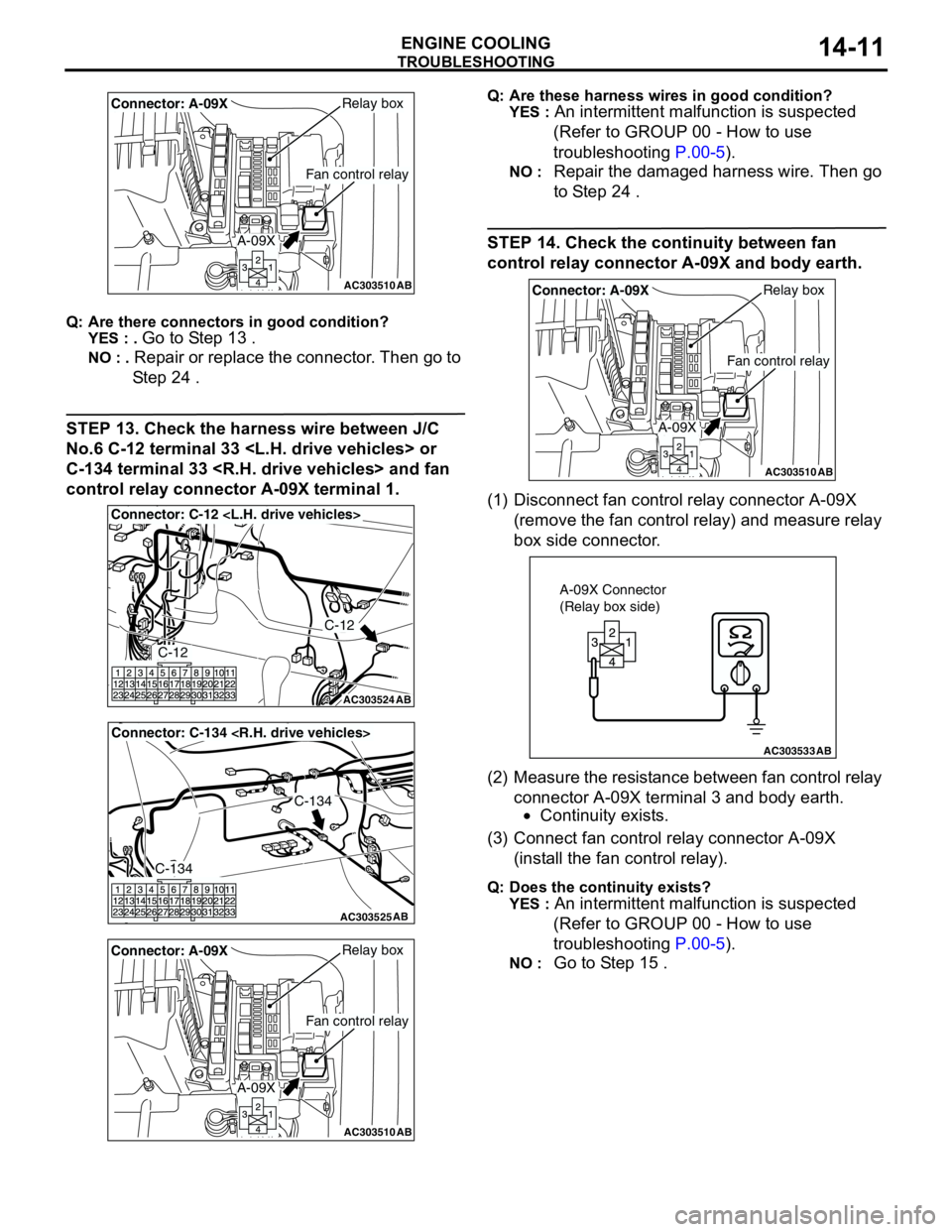
STEP 13. Check the harness wire between J/C
No.6 C-12 terminal 33
C-134 terminal 33
control relay connector A-09X terminal 1.
Q: Are these harness wires in good condition?
YES :
An intermittent malfunction is suspected
(Refer to GROUP 00 - How to use
troubleshooting P.00-5).
NO : Repair the damaged harness wire. Then go
to Step 24 .
STEP 14. Check the continuity between fan
control relay connector A-09X and body earth.
(1) Disconnect fan control relay connector A-09X
(remove the fan control relay) and measure relay
box side connector.
(2) Measure the resistance between fan control relay
connector A-09X terminal 3 and body earth.
•Continuity exists.
(3) Connect fan control relay connector A-09X
(install the fan control relay).
Q: Does the continuity exists?
YES :
An intermittent malfunction is suspected
(Refer to GROUP 00 - How to use
troubleshooting P.00-5).
NO : Go to Step 15 .
AC303510AB
Fan control relay
Relay boxConnector: A-09X
A-09X
AC303524
Connector: C-12
AB
C-12
C-12
AC303525
Connector: C-134
AB
C-134
C-134
AC303510AB
Fan control relay
Relay boxConnector: A-09X
A-09X
AC303510AB
Fan control relay
Relay boxConnector: A-09X
A-09X
AC303533AB
A-09X Connector
(Relay box side)
Page 26 of 788
TROUBLESHOOTING
ENGINE COOLING14-12
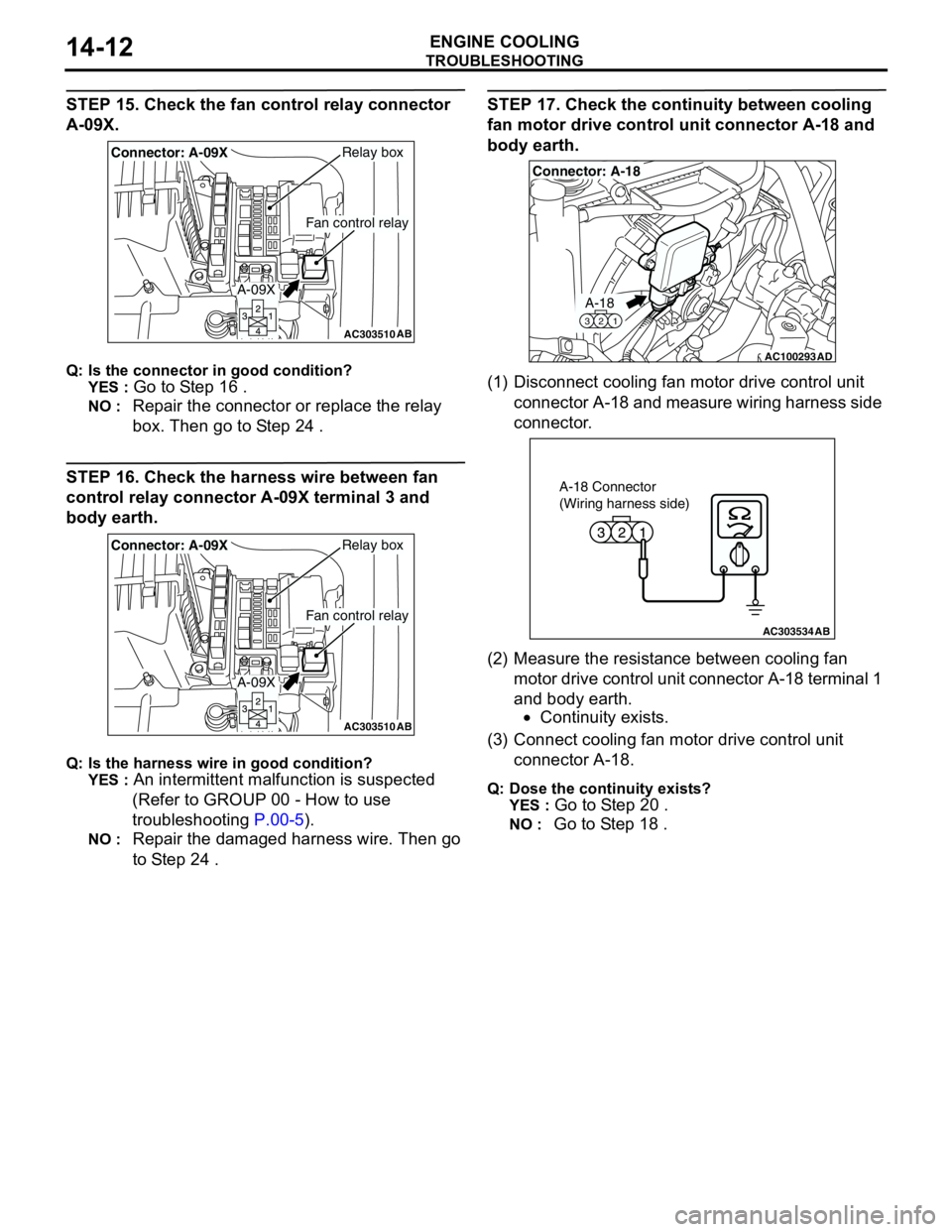
STEP 15. Check the fan control relay connector
A-09X.
Q: Is the connector in good condition?
YES :
Go to Step 16 .
NO : Repair the connector or replace the relay
box. Then go to Step 24 .
STEP 16. Check the harness wire between fan
control relay connector A-09X terminal 3 and
body earth.
Q: Is the harness wire in good condition?
YES :
An intermittent malfunction is suspected
(Refer to GROUP 00 - How to use
troubleshooting P.00-5).
NO : Repair the damaged harness wire. Then go
to Step 24 .
STEP 17. Check the continuity between cooling
fan motor drive control unit connector A-18 and
body earth.
(1) Disconnect cooling fan motor drive control unit
connector A-18 and measure wiring harness side
connector.
(2) Measure the resistance between cooling fan
motor drive control unit connector A-18 terminal 1
and body earth.
•Continuity exists.
(3) Connect cooling fan motor drive control unit
connector A-18.
Q: Dose the continuity exists?
YES :
Go to Step 20 .
NO : Go to Step 18 .
AC303510AB
Fan control relay
Relay boxConnector: A-09X
A-09X
AC303510AB
Fan control relay
Relay boxConnector: A-09X
A-09X
AC100293
A-18
321
Connector: A-18
AD
AC303534AB
A-18 Connector
(Wiring harness side)
Page 27 of 788
TROUBLESHOOTING
ENGINE COOLING14-13
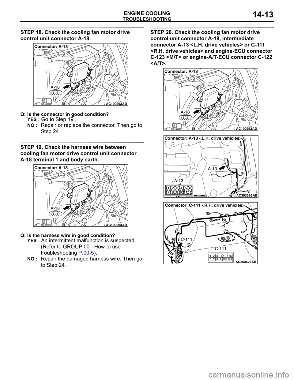
STEP 18. Check the cooling fan motor drive
control unit connector A-18.
Q: Is the connector in good condition?
YES :
Go to Step 19 .
NO : Repair or replace the connector. Then go to
Step 24 .
STEP 19. Check the harness wire between
cooling fan motor drive control unit connector
A-18 terminal 1 and body earth.
Q: Is the harness wire in good condition?
YES :
An intermittent malfunction is suspected
(Refer to GROUP 00 - How to use
troubleshooting P.00-5).
NO : Repair the damaged harness wire. Then go
to Step 24 .
STEP 20. Check the cooling fan motor drive
control unit connector A-18, intermediate
connector A-13
C-123
.
AC100293
A-18
321
Connector: A-18
AD
AC100293
A-18
321
Connector: A-18
AD
AC100293
A-18
321
Connector: A-18
AD
AC303526
Connector: A-13
AB
A-13
A-13
AC303527
Connector: C-111
AB
C-111
C-111
615
121179
810234
Page 29 of 788
TROUBLESHOOTING
ENGINE COOLING14-15
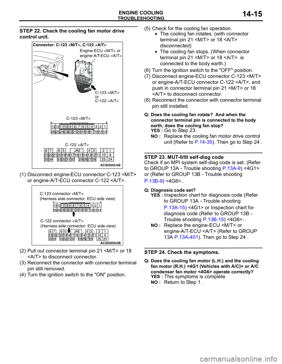
STEP 22. Check the cooling fan motor drive
control unit.
(1) Disconnect engine-ECU connector C-123
or engine-A/T-ECU connector C-122 .
(2) Pull out connector terminal pin 21
to disconnect connector.
(3) Reconnect the connector with connector terminal
pin still removed.
(4) Turn the ignition switch to the "ON" position.(5) Check for the cooling fan operation.
•The cooling fan rotates. (with connector
terminal pin 21
disconnected)
•The cooling fan stops. (When connector
terminal pin 21
connected to the body earth.)
(6) Turn the ignition switch to the "OFF" position.
(7) Disconnect engine-ECU connector C-123
or engine-A/T-ECU connector C-122 , and
push in connector terminal pin 21
to disconnect connector.
(8) Reconnect the connector with connector terminal
pin still installed.
Q: Does the cooling fan rotate? And when the
connector terminal pin is connected to the body
earth, does the cooling fan stop?
YES :
Go to Step 23 .
NO : Replace the cooling fan motor drive control
unit (Refer to P.14-35). Then go to Step 24 .
STEP 23. MUT-II/III self-diag code
Check if an MPI system self-diag code is set. (Refer
to GROUP 13A - Trouble shooting P.13A-9) <4G1>
or (Refer to GROUP 13B - Trouble shooting
P.13B-9) <4G6>.
Q: Diagnosis code set?
YES :
Inspection chart for diagnosis code (Refer
to GROUP 13A - Trouble shooting
P.13A-15) <4G1> or Inspection chart for
diagnosis code (Refer to GROUP 13B -
Trouble shooting P.13B-15) <4G6>.
NO : Replace the engine-ECU
engine-A/T-ECU (Refer to GROUP
13A P.13A-401). Then go to Step 24 .
STEP 24. Check the symptoms.
Q: Does the cooling fan motor (L.H.) and the cooling
fan motor (R.H.) <4G1 (Vehicles with A/C)> or A/C
condenser fan motor <4G6> operate correctly?
YES :
This symptoms is complete.
NO : Return to Step 1 .
AC303555AB
Connector: C-123
C-123
or
C-122
C-123
Engine-ECU
engine-A/T-ECU
C-122
AC303559
C-122 connector
(Harness side connector: ECU side view)
AB
C-123 connector
(Harness side connector: ECU side view)
Page 33 of 788
TROUBLESHOOTING
ENGINE COOLING14-19
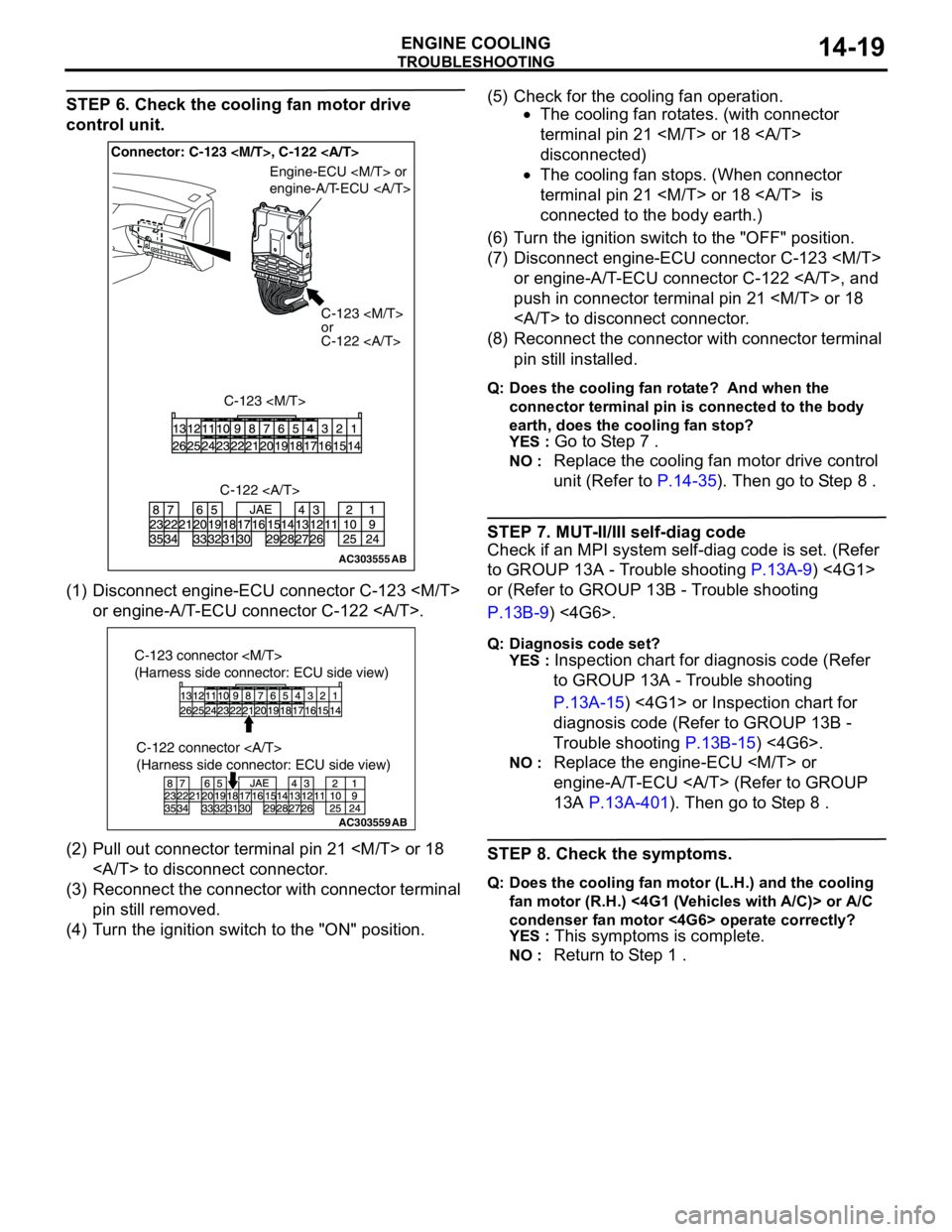
STEP 6. Check the cooling fan motor drive
control unit.
(1) Disconnect engine-ECU connector C-123
or engine-A/T-ECU connector C-122 .
(2) Pull out connector terminal pin 21
to disconnect connector.
(3) Reconnect the connector with connector terminal
pin still removed.
(4) Turn the ignition switch to the "ON" position.(5) Check for the cooling fan operation.
•The cooling fan rotates. (with connector
terminal pin 21
disconnected)
•The cooling fan stops. (When connector
terminal pin 21
connected to the body earth.)
(6) Turn the ignition switch to the "OFF" position.
(7) Disconnect engine-ECU connector C-123
or engine-A/T-ECU connector C-122 , and
push in connector terminal pin 21
to disconnect connector.
(8) Reconnect the connector with connector terminal
pin still installed.
Q: Does the cooling fan rotate? And when the
connector terminal pin is connected to the body
earth, does the cooling fan stop?
YES :
Go to Step 7 .
NO : Replace the cooling fan motor drive control
unit (Refer to P.14-35). Then go to Step 8 .
STEP 7. MUT-II/III self-diag code
Check if an MPI system self-diag code is set. (Refer
to GROUP 13A - Trouble shooting P.13A-9) <4G1>
or (Refer to GROUP 13B - Trouble shooting
P.13B-9) <4G6>.
Q: Diagnosis code set?
YES :
Inspection chart for diagnosis code (Refer
to GROUP 13A - Trouble shooting
P.13A-15) <4G1> or Inspection chart for
diagnosis code (Refer to GROUP 13B -
Trouble shooting P.13B-15) <4G6>.
NO : Replace the engine-ECU
engine-A/T-ECU (Refer to GROUP
13A P.13A-401). Then go to Step 8 .
STEP 8. Check the symptoms.
Q: Does the cooling fan motor (L.H.) and the cooling
fan motor (R.H.) <4G1 (Vehicles with A/C)> or A/C
condenser fan motor <4G6> operate correctly?
YES :
This symptoms is complete.
NO : Return to Step 1 .
AC303555AB
Connector: C-123
C-123
or
C-122
C-123
Engine-ECU
engine-A/T-ECU
C-122
AC303559
C-122 connector
(Harness side connector: ECU side view)
AB
C-123 connector
(Harness side connector: ECU side view)
Page 45 of 788
WATER HOSE AND WATER PIPE
ENGINE COOLING14-31
WATER HOSE AND WATER PIPE
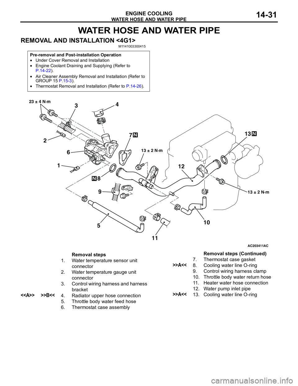
REMOVAL AND INSTALLATION <4G1>M1141003300415
Pre-removal and Post-installation Operation
•Under Cover Removal and Installation
•Engine Coolant Draining and Supplying (Refer to
P.14-22).
•Air Cleaner Assembly Removal and Installation (Refer to
GROUP 15 P.15-3).
•Thermostat Removal and Installation (Refer to P.14-26).
AC203411
1 234
5 67
8
10 9
13 ± 2 N·m 23 ± 4 N·m
13 ± 2 N·m
N
N
AC
111213
N
Removal steps
1. Water temperature sensor unit
connector
2. Water temperature gauge unit
connector
3. Control wiring harness and harness
bracket
<> >>B<<4. Radiator upper hose connection
5. Throttle body water feed hose
6. Thermostat case assembly7. Thermostat case gasket
>>A<<8. Cooling water line O-ring
9. Control wiring harness clamp
10. Throttle body water return hose
11. Heater water hose connection
12. Water pump inlet pipe
>>A<<13. Cooling water line O-ringRemoval steps (Continued)