Body MITSUBISHI LANCER 2005 User Guide
[x] Cancel search | Manufacturer: MITSUBISHI, Model Year: 2005, Model line: LANCER, Model: MITSUBISHI LANCER 2005Pages: 788, PDF Size: 45.98 MB
Page 47 of 788
WATER HOSE AND WATER PIPE
ENGINE COOLING14-33
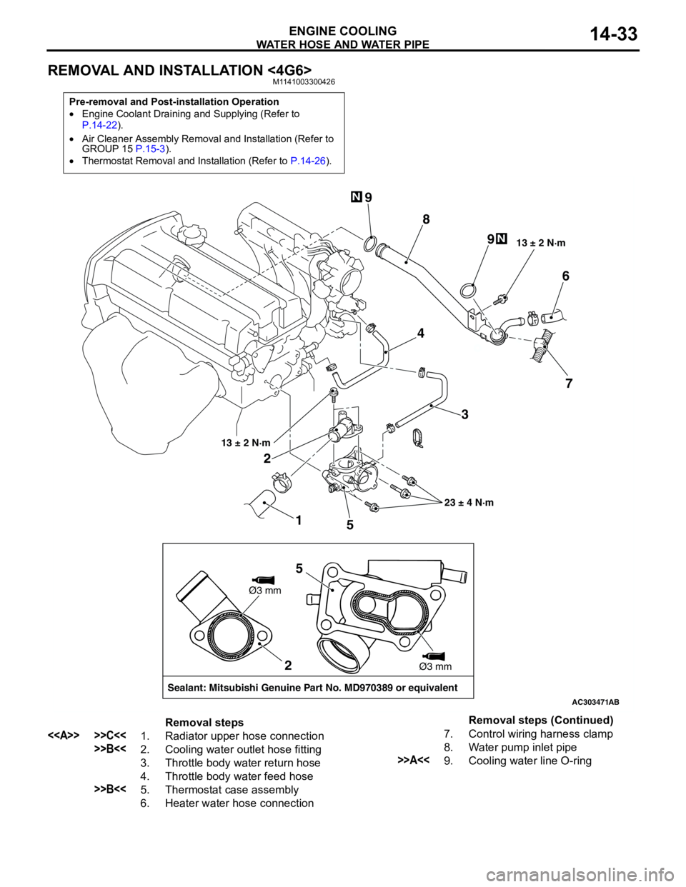
REMOVAL AND INSTALLATION <4G6>M1141003300426
Pre-removal and Post-installation Operation
•Engine Coolant Draining and Supplying (Refer to
P.14-22).
•Air Cleaner Assembly Removal and Installation (Refer to
GROUP 15 P.15-3).
•Thermostat Removal and Installation (Refer to P.14-26).
AC303471
1 23 4
56
7 8 9
9
13 ± 2 N·m
23 ± 4 N·m 13 ± 2 N·m
N
N
AB
2
Sealant: Mitsubishi Genuine Part No. MD970389 or equivalentØ3 mm
Ø3 mm
5
Removal steps
<> >>C<<1. Radiator upper hose connection
>>B<<2. Cooling water outlet hose fitting
3. Throttle body water return hose
4. Throttle body water feed hose
>>B<<5. Thermostat case assembly
6. Heater water hose connection7. Control wiring harness clamp
8. Water pump inlet pipe
>>A<<9. Cooling water line O-ringRemoval steps (Continued)
Page 48 of 788
Page 55 of 788
AIR CLEANER
INTAKE AND EXHAUST15-3
AIR CLEANER
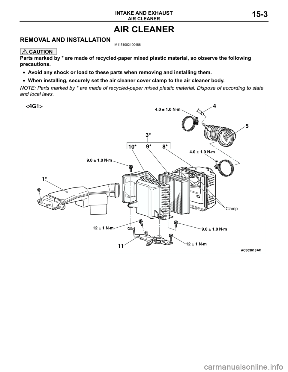
REMOVAL AND INSTALLATIONM1151002100486
CAUTION
Parts marked by * are made of recycled-paper mixed plastic material, so observe the following
precautions.
•Avoid any shock or load to these parts when removing and installing them.
•When installing, securely set the air cleaner cover clamp to the air cleaner body.
NOTE: Parts marked by * are made of recycled-paper mixed plastic material. Dispose of according to state
and local laws.
AC303618
4.0 ± 1.0 N·m 4.0 ± 1.0 N·m
10*9*4
1*5
11
12 ± 1 N·m
9.0 ± 1.0 N·m 9.0 ± 1.0 N·m
AB
12 ± 1 N·m
Clamp
8*
3* <4G1>
Page 56 of 788
AIR CLEANER
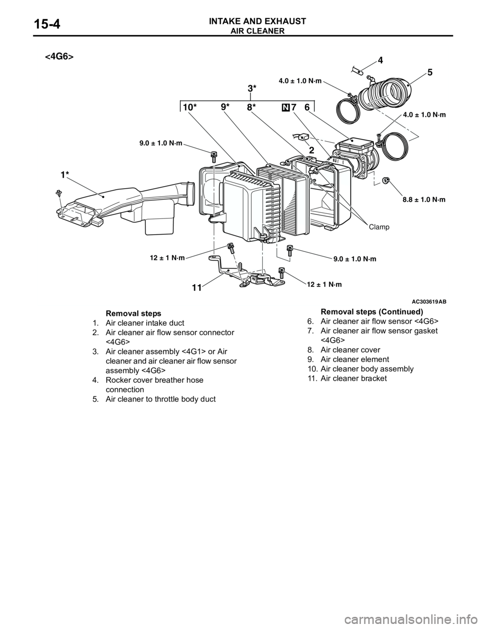
INTAKE AND EXHAUST15-4
AC303619
4.0 ± 1.0 N·m 4.0 ± 1.0 N·m10*9*4
1*5
11
12 ± 1 N·m
9.0 ± 1.0 N·m 9.0 ± 1.0 N·m
AB
12 ± 1 N·m
Clamp
8*
3* <4G6>
6 7
N
2
8.8 ± 1.0 N·m
Removal steps
1. Air cleaner intake duct
2. Air cleaner air flow sensor connector
<4G6>
3. Air cleaner assembly <4G1> or Air
cleaner and air cleaner air flow sensor
assembly <4G6>
4. Rocker cover breather hose
connection
5. Air cleaner to throttle body duct6. Air cleaner air flow sensor <4G6>
7. Air cleaner air flow sensor gasket
<4G6>
8. Air cleaner cover
9. Air cleaner element
10. Air cleaner body assembly
11. Air cleaner bracketRemoval steps (Continued)
Page 57 of 788
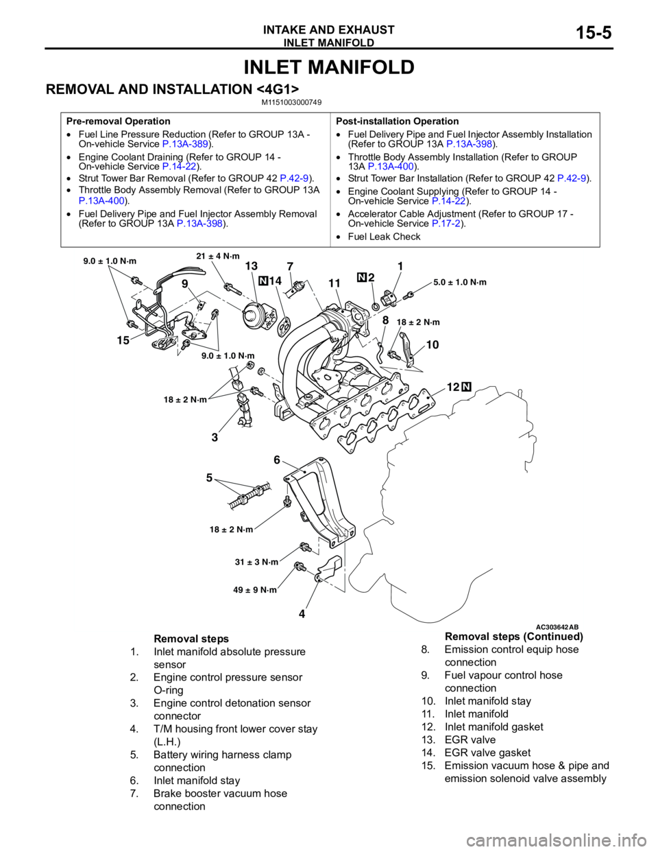
INLET MANIFOLD
INTAKE AND EXHAUST15-5
INLET MANIFOLD
REMOVAL AND INSTALLATION <4G1>M1151003000749
Pre-removal Operation
•Fuel Line Pressure Reduction (Refer to GROUP 13A -
On-vehicle Service P.13A-389).
•Engine Coolant Draining (Refer to GROUP 14 -
On-vehicle Service P.14-22).
•Strut Tower Bar Removal (Refer to GROUP 42 P.42-9).
•Throttle Body Assembly Removal (Refer to GROUP 13A
P.13A-400).
•Fuel Delivery Pipe and Fuel Injector Assembly Removal
(Refer to GROUP 13A P.13A-398).Post-installation Operation
•Fuel Delivery Pipe and Fuel Injector Assembly Installation
(Refer to GROUP 13A P.13A-398).
•Throttle Body Assembly Installation (Refer to GROUP
13A P.13A-400).
•Strut Tower Bar Installation (Refer to GROUP 42 P.42-9).
•Engine Coolant Supplying (Refer to GROUP 14 -
On-vehicle Service P.14-22).
•Accelerator Cable Adjustment (Refer to GROUP 17 -
On-vehicle Service P.17-2).
•Fuel Leak Check
AC303642AB
15
3
6
5
412 10 71
2
11
913
14
21 ± 4 N·m
9.0 ± 1.0 N·m
9.0 ± 1.0 N·m
18 ± 2 N·m
18 ± 2 N·m18 ± 2 N·m5.0 ± 1.0 N·m
31 ± 3 N·m
49 ± 9 N·m
N
N
N
8
Removal steps
1. Inlet manifold absolute pressure
sensor
2. Engine control pressure sensor
O-ring
3. Engine control detonation sensor
connector
4. T/M housing front lower cover stay
(L.H.)
5. Battery wiring harness clamp
connection
6. Inlet manifold stay
7. Brake booster vacuum hose
connection8. Emission control equip hose
connection
9. Fuel vapour control hose
connection
10. Inlet manifold stay
11. Inlet manifold
12. Inlet manifold gasket
13. EGR valve
14. EGR valve gasket
15. Emission vacuum hose & pipe and
emission solenoid valve assembly Removal steps (Continued)
Page 58 of 788
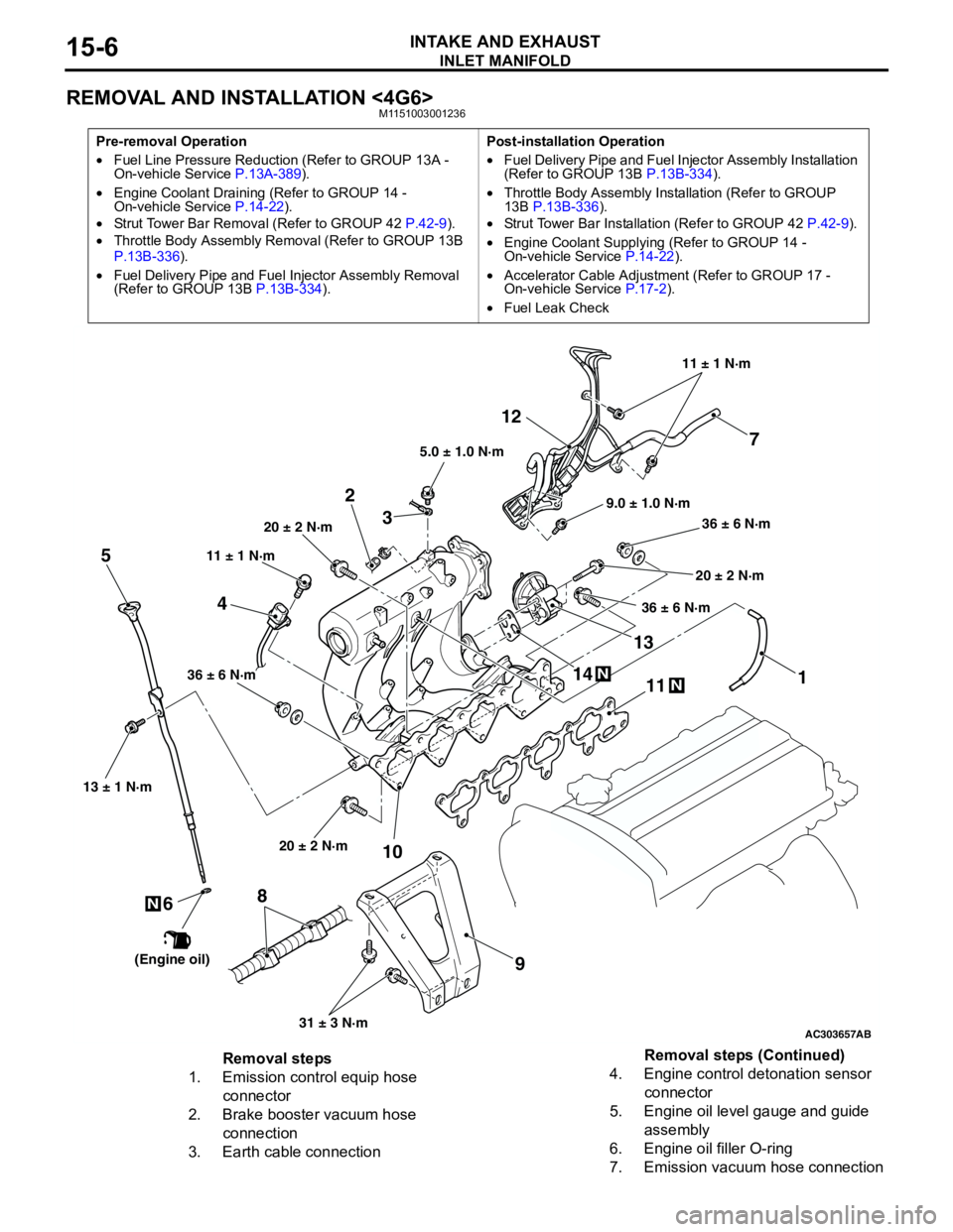
INLET MANIFOLD
INTAKE AND EXHAUST15-6
REMOVAL AND INSTALLATION <4G6>M1151003001236
Pre-removal Operation
•Fuel Line Pressure Reduction (Refer to GROUP 13A -
On-vehicle Service P.13A-389).
•Engine Coolant Draining (Refer to GROUP 14 -
On-vehicle Service P.14-22).
•Strut Tower Bar Removal (Refer to GROUP 42 P.42-9).
•Throttle Body Assembly Removal (Refer to GROUP 13B
P.13B-336).
•Fuel Delivery Pipe and Fuel Injector Assembly Removal
(Refer to GROUP 13B P.13B-334).Post-installation Operation
•Fuel Delivery Pipe and Fuel Injector Assembly Installation
(Refer to GROUP 13B P.13B-334).
•Throttle Body Assembly Installation (Refer to GROUP
13B P.13B-336).
•Strut Tower Bar Installation (Refer to GROUP 42 P.42-9).
•Engine Coolant Supplying (Refer to GROUP 14 -
On-vehicle Service P.14-22).
•Accelerator Cable Adjustment (Refer to GROUP 17 -
On-vehicle Service P.17-2).
•Fuel Leak Check
AC303657
9.0 ± 1.0 N·m11 ± 1 N·m
20 ± 2 N·m
31 ± 3 N·m 36 ± 6 N·m
20 ± 2 N·m
20 ± 2 N·m
36 ± 6 N·m
36 ± 6 N·m
11
9 10 212
N1413N
AB
5.0 ± 1.0 N·m
3
1
11 ± 1 N·m
4
N
13 ± 1 N·m
5
6
(Engine oil)
7
8
Removal steps
1. Emission control equip hose
connector
2. Brake booster vacuum hose
connection
3. Earth cable connection4. Engine control detonation sensor
connector
5. Engine oil level gauge and guide
assembly
6. Engine oil filler O-ring
7. Emission vacuum hose connectionRemoval steps (Continued)
Page 70 of 788

CHARGING SYSTEM
ENGINE ELECTRICAL16-6
7. Connect a tachometer or the MUT-II/III (Refer to
GROUP 11A − On-vehicle Service − Idle speed
check <4G1> P.11A-11 or GROUP 11C −
On-vehicle Service − Idle speed check <4G6>
P.11C-11).
8. Leave the hood open.
9. Check that the reading on the voltmeter is equal
to the battery voltage.
NOTE: If the voltage is 0 V, the cause is probably
an open circuit in the wire or fusible link between
the alternator "B" terminal and the battery (+)
terminal.
10.Turn the light switch on to turn on headlamps and
then start the engine.
11.Immediately after setting the headlamps to high
beam and turning the heater blower switch to the
high revolution position, increase the engine
speed to 2,500 r/min and read the maximum
current output value displayed on the ammeter.
Limit: 70 % of normal current outputNOTE: .
•For the nominal current output, refer to the
Alternator Specifications.
•Because the current from the battery will soon
drop after the engine is started, the above step
should be carried out as quickly as possible in
order to obtain the maximum current output
value.
•The current output value will depend on the
electrical load and the temperature of the
alternator body.
•If the electrical load is small while testing, the
specified level of current may not be output
even though the alternator is normal. In such
cases, increase the electrical load by leaving
the headlamps turned on for some time to
discharge the battery or by using the lighting
system in another vehicle, and then test again.
•The specified level of current also may not be
output if the temperature of the alternator body
or the ambient temperature is too high. In such
cases, cool the alternator and then test again.
12.The reading on the ammeter should be above the
limit value. If the reading is below the limit value
and the alternator output wire is normal, remove
the alternator from the engine and check the
alternator.
13.Run the engine at idle after the test.
14.Turn the ignition switch to the "LOCK" (OFF)
position.
15.Remove the tachometer or the MUT-II/III.
16.Disconnect the negative battery cable.
17.Disconnect the ammeter and voltmeter.
18.Connect the negative battery cable.
Page 88 of 788
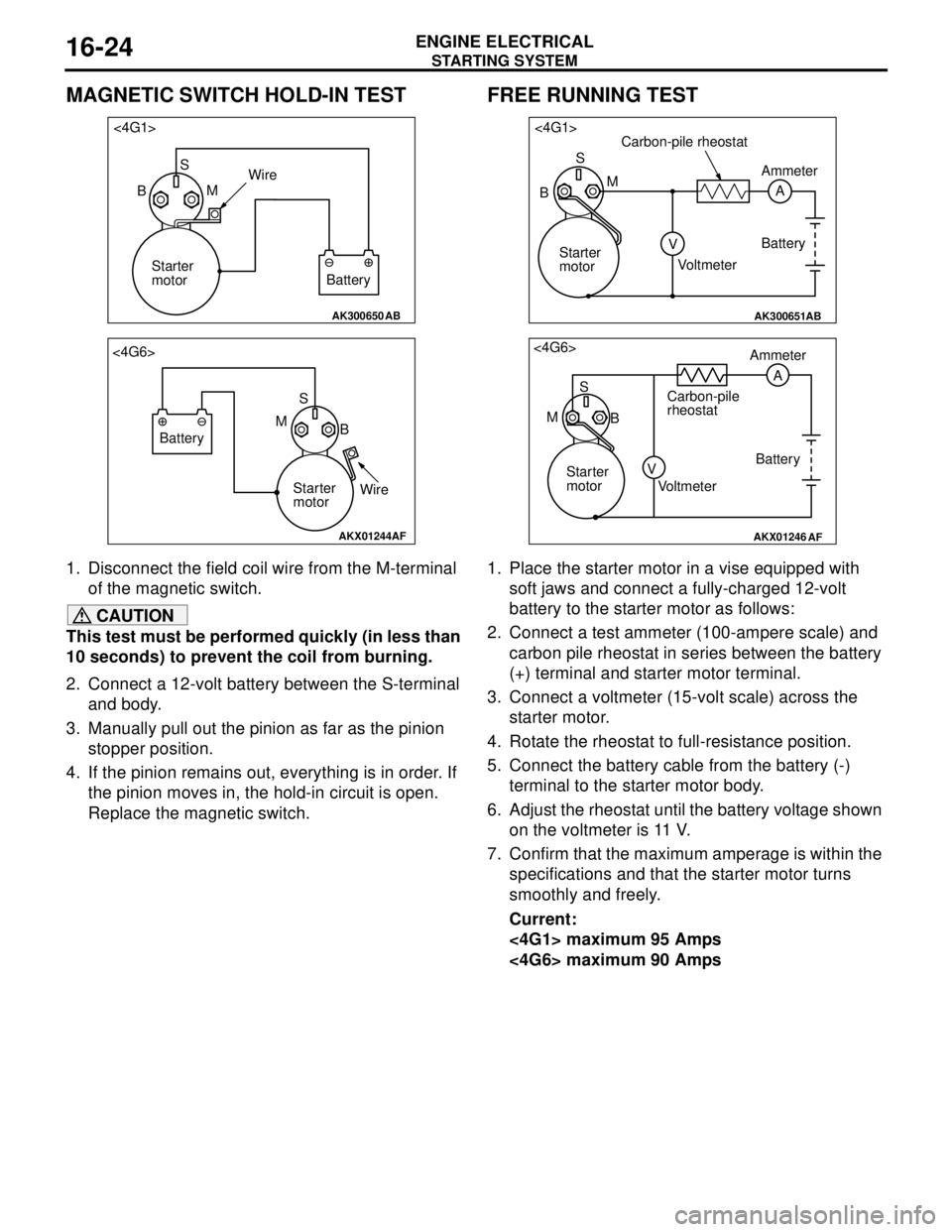
STARTING SYSTEM
ENGINE ELECTRICAL16-24
MAGNETIC SWITCH HOLD-IN TEST
1. Disconnect the field coil wire from the M-terminal
of the magnetic switch.
CAUTION
This test must be performed quickly (in less than
10 seconds) to prevent the coil from burning.
2. Connect a 12-volt battery between the S-terminal
and body.
3. Manually pull out the pinion as far as the pinion
stopper position.
4. If the pinion remains out, everything is in order. If
the pinion moves in, the hold-in circuit is open.
Replace the magnetic switch.
FREE RUNNING TEST
1. Place the starter motor in a vise equipped with
soft jaws and connect a fully-charged 12-volt
battery to the starter motor as follows:
2. Connect a test ammeter (100-ampere scale) and
carbon pile rheostat in series between the battery
(+) terminal and starter motor terminal.
3. Connect a voltmeter (15-volt scale) across the
starter motor.
4. Rotate the rheostat to full-resistance position.
5. Connect the battery cable from the battery (-)
terminal to the starter motor body.
6. Adjust the rheostat until the battery voltage shown
on the voltmeter is 11 V.
7. Confirm that the maximum amperage is within the
specifications and that the starter motor turns
smoothly and freely.
Current:
<4G1> maximum 95 Amps
<4G6> maximum 90 Amps
AK300650AB
<4G1>
S
BMWire
Battery Starter
motor
AKX01244
<4G6>
S
B M
Battery
Starter
motorWire
AF
AK300651AB
<4G1>
S
A M
V BCarbon-pile rheostat
Battery
VoltmeterAmmeter
Starter
motor
AKX01246
<4G6>
S
M
BAmmeter
Carbon-pile
rheostat
Battery
Starter
motor
Voltmeter
AF
A
V
Page 89 of 788
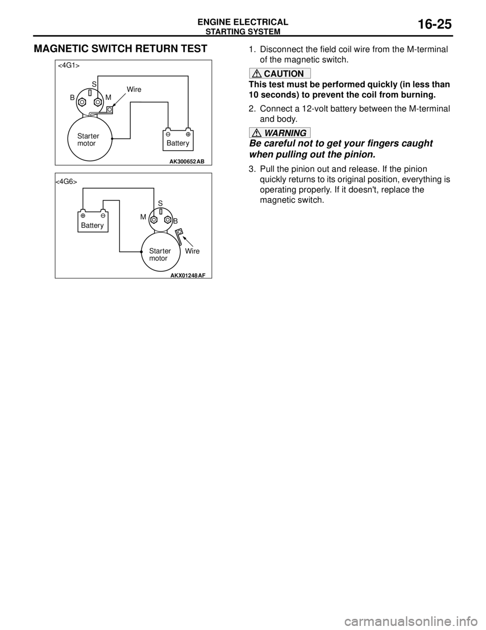
STARTING SYSTEM
ENGINE ELECTRICAL16-25
MAGNETIC SWITCH RETURN TEST1. Disconnect the field coil wire from the M-terminal
of the magnetic switch.
CAUTION
This test must be performed quickly (in less than
10 seconds) to prevent the coil from burning.
2. Connect a 12-volt battery between the M-terminal
and body.
WARNING
Be careful not to get your fingers caught
when pulling out the pinion.
3. Pull the pinion out and release. If the pinion
quickly returns to its original position, everything is
operating properly. If it doesn't, replace the
magnetic switch.
AK300652AB
<4G1>
S
BMWire
Battery Starter
motor
AKX01248
<4G6>
S
B M
Battery
Starter
motorWire
AF
Page 93 of 788
STARTING SYSTEM
ENGINE ELECTRICAL16-29
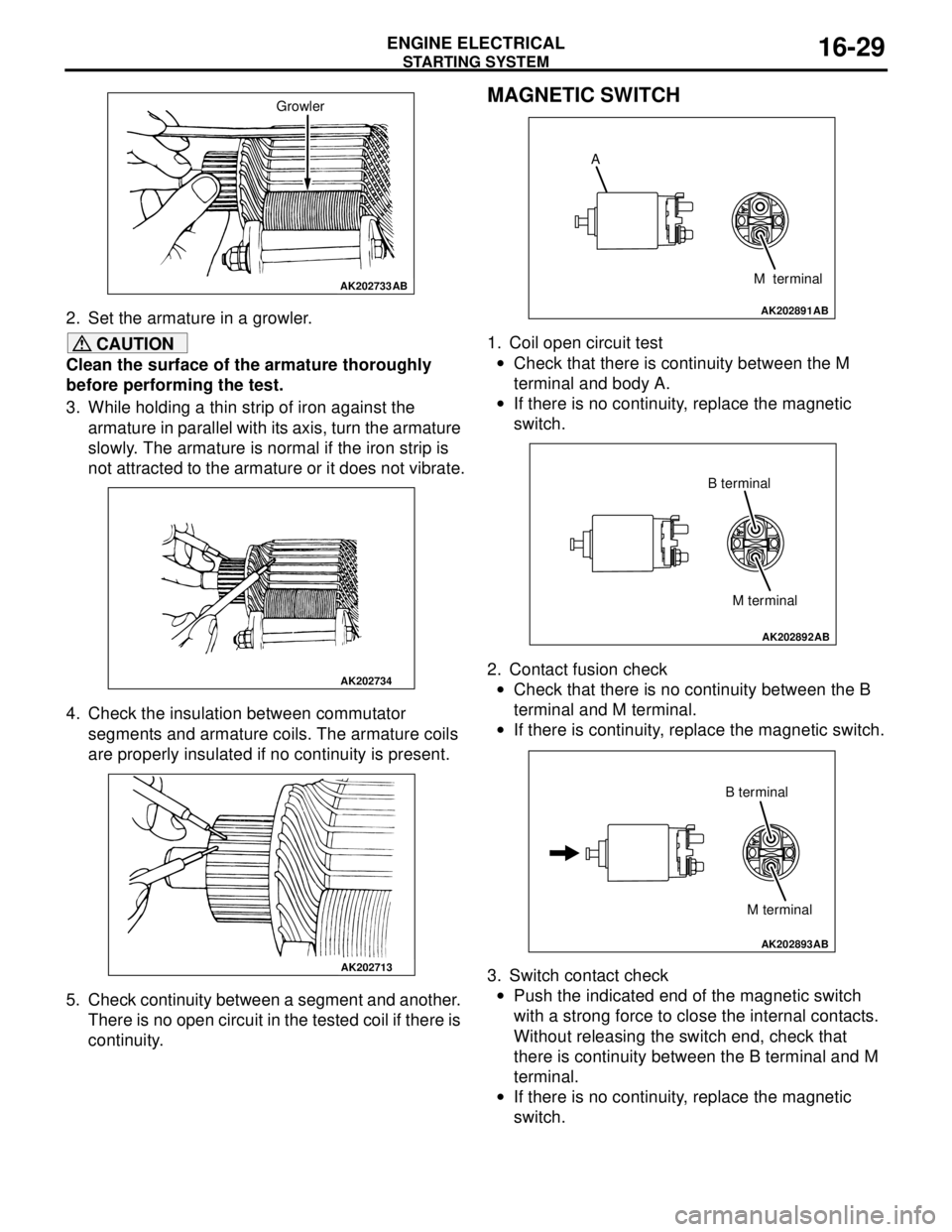
2. Set the armature in a growler.
CAUTION
Clean the surface of the armature thoroughly
before performing the test.
3. While holding a thin strip of iron against the
armature in parallel with its axis, turn the armature
slowly. The armature is normal if the iron strip is
not attracted to the armature or it does not vibrate.
4. Check the insulation between commutator
segments and armature coils. The armature coils
are properly insulated if no continuity is present.
5. Check continuity between a segment and another.
There is no open circuit in the tested coil if there is
continuity.
MAGNETIC SWITCH
1. Coil open circuit test
•Check that there is continuity between the M
terminal and body A.
•If there is no continuity, replace the magnetic
switch.
2. Contact fusion check
•Check that there is no continuity between the B
terminal and M terminal.
•If there is continuity, replace the magnetic switch.
3. Switch contact check
•Push the indicated end of the magnetic switch
with a strong force to close the internal contacts.
Without releasing the switch end, check that
there is continuity between the B terminal and M
terminal.
•If there is no continuity, replace the magnetic
switch.
AK202733
Growler
AB
AK202734
AK202713
AK202891
A
M terminal
AB
AK202892
M terminal B terminal
AB
AK202893
M terminal B terminal
AB