Body MITSUBISHI LANCER 2005 Owner's Manual
[x] Cancel search | Manufacturer: MITSUBISHI, Model Year: 2005, Model line: LANCER, Model: MITSUBISHI LANCER 2005Pages: 788, PDF Size: 45.98 MB
Page 111 of 788
ENGINE CONTROL
ENGINE AND EMISSION CONTROL17-3
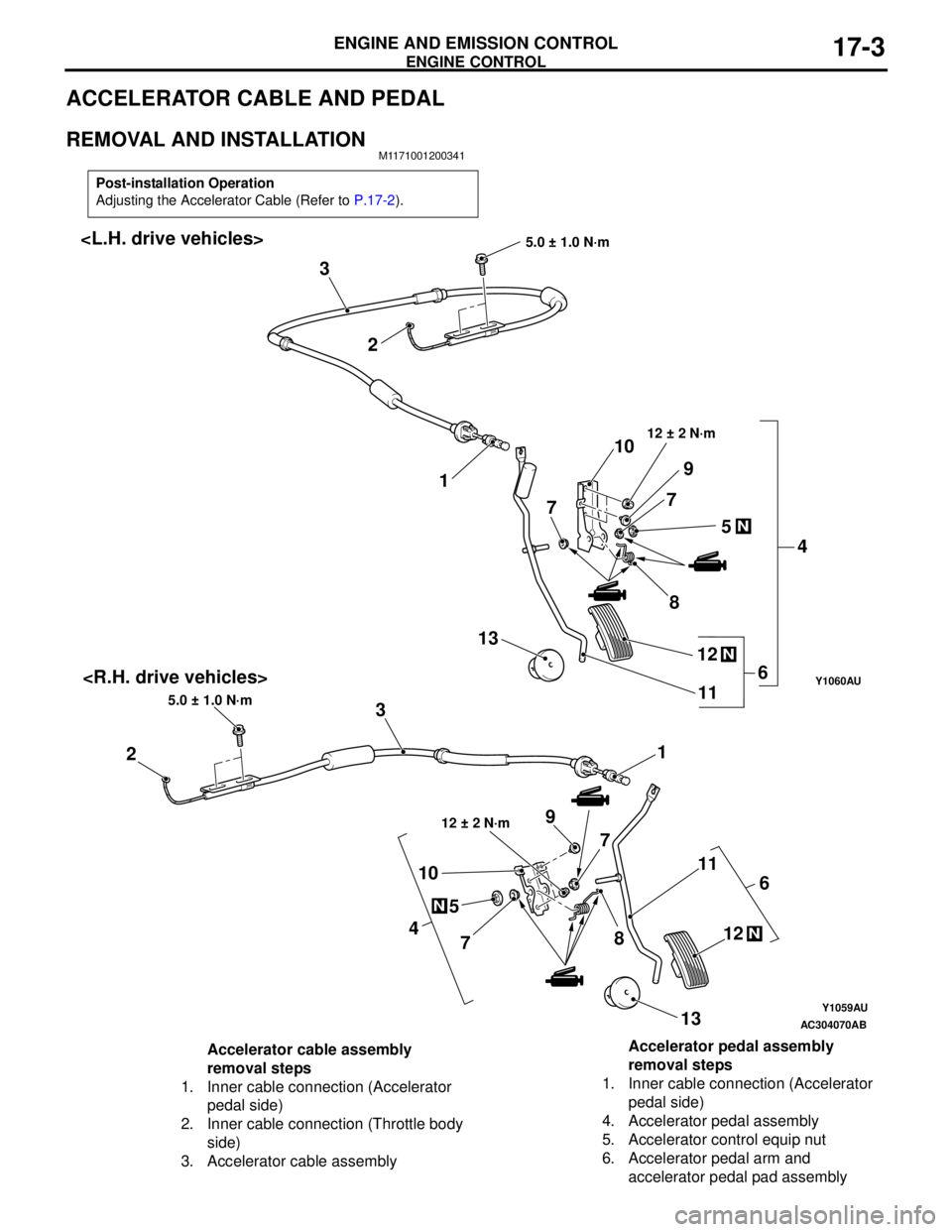
ACCELERATOR CABLE AND PEDAL
REMOVAL AND INSTALLATIONM1171001200341
Post-installation Operation
Adjusting the Accelerator Cable (Refer to P.17-2).
Y1059AU
Y1060AU
AC304070
N
4
5
78 1011
N12
13
AB
1
23
5.0 ± 1.0 N·m
6
12 ± 2 N·m9
7
1 2 3
5.0 ± 1.0 N·m
N
4 5 7
8 10
11
N12 13
6
12 ± 2 N·m
9
7
Accelerator cable assembly
removal steps
1. Inner cable connection (Accelerator
pedal side)
2. Inner cable connection (Throttle body
side)
3. Accelerator cable assemblyAccelerator pedal assembly
removal steps
1. Inner cable connection (Accelerator
pedal side)
4. Accelerator pedal assembly
5. Accelerator control equip nut
6. Accelerator pedal arm and
accelerator pedal pad assembly
Page 115 of 788
EMISSION CONTROL
ENGINE AND EMISSION CONTROL17-7
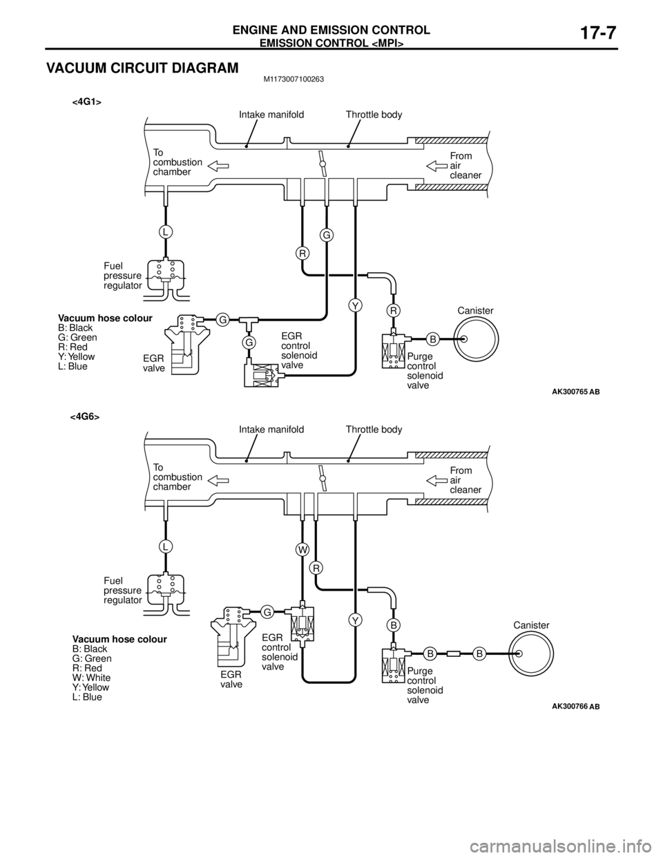
VACUUM CIRCUIT DIAGRAMM1173007100263
AK300765
From
air
cleaner To
combustion
chamberThrottle body
B R
AB
Intake manifold
Y G
G
GR L
Fuel
pressure
regulator
EGR
valveEGR
control
solenoid
valvePurge
control
solenoid
valveCanister
Vacuum hose colour
B: Black
G: Green
R: Red
Y: Yellow
L: Blue
<4G1>
AK300766
From
air
cleaner To
combustion
chamberThrottle body
B B
AB
Intake manifold
Y R
GW L
Fuel
pressure
regulator
EGR
valveEGR
control
solenoid
valve
Purge
control
solenoid
valveCanister
Vacuum hose colour
B: Black
G: Green
R: Red
W: White
Y: Yellow
L: Blue
<4G6>
B
Page 118 of 788
EMISSION CONTROL
ENGINE AND EMISSION CONTROL17-10
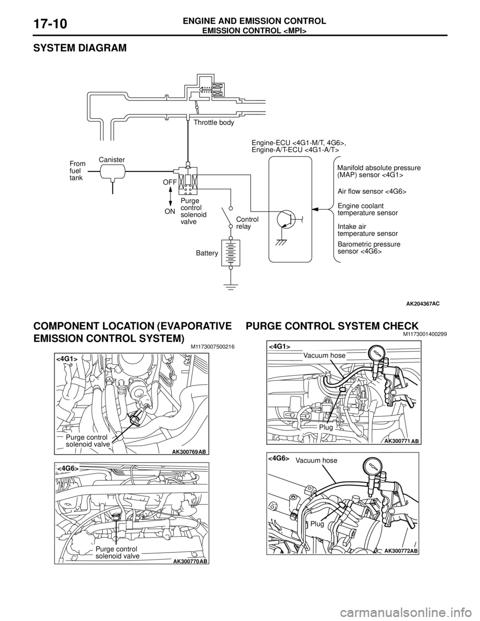
SYSTEM DIAGRAM
COMPONENT LOCATION (EVAPORATIVE
EMISSION CONTROL SYSTEM)
M1173007500216
PURGE CONTROL SYSTEM CHECKM1173001400299
AK204367AC
Throttle body
Canister
From
fuel
tank
OFF
ONPurge
control
solenoid
valveControl
relay
BatteryEngine-ECU <4G1-M/T, 4G6>,
Engine-A/T-ECU <4G1-A/T>
Air flow sensor <4G6>
Engine coolant
temperature sensor
Intake air
temperature sensor
Barometric pressure
sensor <4G6> Manifold absolute pressure
(MAP) sensor <4G1>
AK300769
<4G1>
AB
Purge control
solenoid valve
AK300770
<4G6>
AB
Purge control
solenoid valve
AK300771
<4G1>
AB
Plug
Vacuum hose
AK300772
<4G6>
AB
Plug
Vacuum hose
Page 119 of 788
EMISSION CONTROL
ENGINE AND EMISSION CONTROL17-11
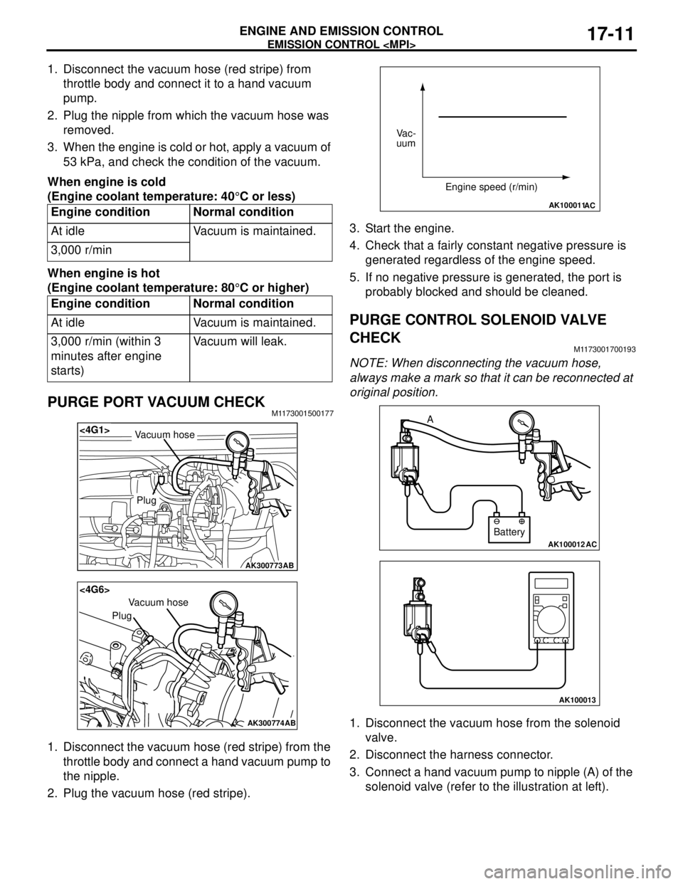
1. Disconnect the vacuum hose (red stripe) from
throttle body and connect it to a hand vacuum
pump.
2. Plug the nipple from which the vacuum hose was
removed.
3. When the engine is cold or hot, apply a vacuum of
53 kPa, and check the condition of the vacuum.
When engine is cold
(Engine coolant temperature: 40°C or less)
When engine is hot
(Engine coolant temperature: 80°C or higher)
PURGE PORT VACUUM CHECKM1173001500177
1. Disconnect the vacuum hose (red stripe) from the
throttle body and connect a hand vacuum pump to
the nipple.
2. Plug the vacuum hose (red stripe).3. Start the engine.
4. Check that a fairly constant negative pressure is
generated regardless of the engine speed.
5. If no negative pressure is generated, the port is
probably blocked and should be cleaned.
PURGE CONTROL SOLENOID VALVE
CHECK
M1173001700193
NOTE: When disconnecting the vacuum hose,
always make a mark so that it can be reconnected at
original position.
1. Disconnect the vacuum hose from the solenoid
valve.
2. Disconnect the harness connector.
3. Connect a hand vacuum pump to nipple (A) of the
solenoid valve (refer to the illustration at left). Engine condition Normal condition
At idle Vacuum is maintained.
3,000 r/min
Engine condition Normal condition
At idle Vacuum is maintained.
3,000 r/min (within 3
minutes after engine
starts)Vacuum will leak.
AK300773
<4G1>
AB
Plug
Vacuum hose
AK300774
<4G6>
AB
Plug
Vacuum hose
AK100011AC
Vac-
uum
Engine speed (r/min)
AK100012AC
Battery A
AK100013
Page 124 of 788
EMISSION CONTROL
ENGINE AND EMISSION CONTROL17-16
5. Replace the gasket, and tighten to the specified
torque.
Tightening torque:
<4G1> 21 ± 4 N⋅m
<4G6> 20 ± 2 N⋅m
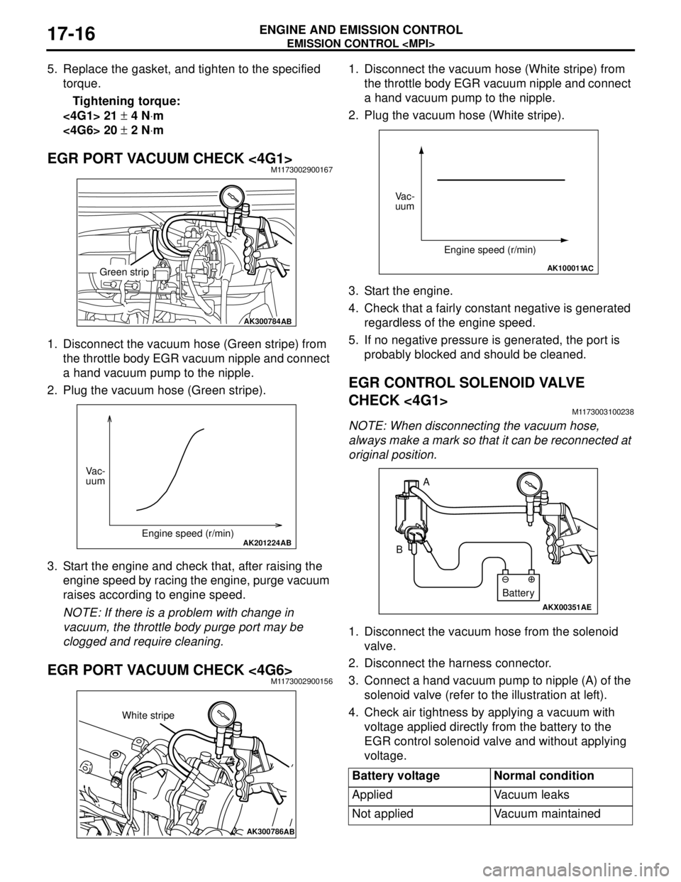
EGR PORT VACUUM CHECK <4G1>M1173002900167
1. Disconnect the vacuum hose (Green stripe) from
the throttle body EGR vacuum nipple and connect
a hand vacuum pump to the nipple.
2. Plug the vacuum hose (Green stripe).
3. Start the engine and check that, after raising the
engine speed by racing the engine, purge vacuum
raises according to engine speed.
NOTE: If there is a problem with change in
vacuum, the throttle body purge port may be
clogged and require cleaning.
EGR PORT VACUUM CHECK <4G6>M1173002900156
1. Disconnect the vacuum hose (White stripe) from
the throttle body EGR vacuum nipple and connect
a hand vacuum pump to the nipple.
2. Plug the vacuum hose (White stripe).
3. Start the engine.
4. Check that a fairly constant negative is generated
regardless of the engine speed.
5. If no negative pressure is generated, the port is
probably blocked and should be cleaned.
EGR CONTROL SOLENOID VALVE
CHECK <4G1>
M1173003100238
NOTE: When disconnecting the vacuum hose,
always make a mark so that it can be reconnected at
original position.
1. Disconnect the vacuum hose from the solenoid
valve.
2. Disconnect the harness connector.
3. Connect a hand vacuum pump to nipple (A) of the
solenoid valve (refer to the illustration at left).
4. Check air tightness by applying a vacuum with
voltage applied directly from the battery to the
EGR control solenoid valve and without applying
voltage.
AK300784AB
Green strip
AK201224AB
Vac-
uum
Engine speed (r/min)
AK300786AB
White stripe
Battery voltage Normal condition
Applied Vacuum leaks
Not applied Vacuum maintained
AK100011AC
Vac-
uum
Engine speed (r/min)
AKX00351
A
B
AE
Battery
Page 136 of 788
SPECIAL TOOLS
FRONT AXLE26-4
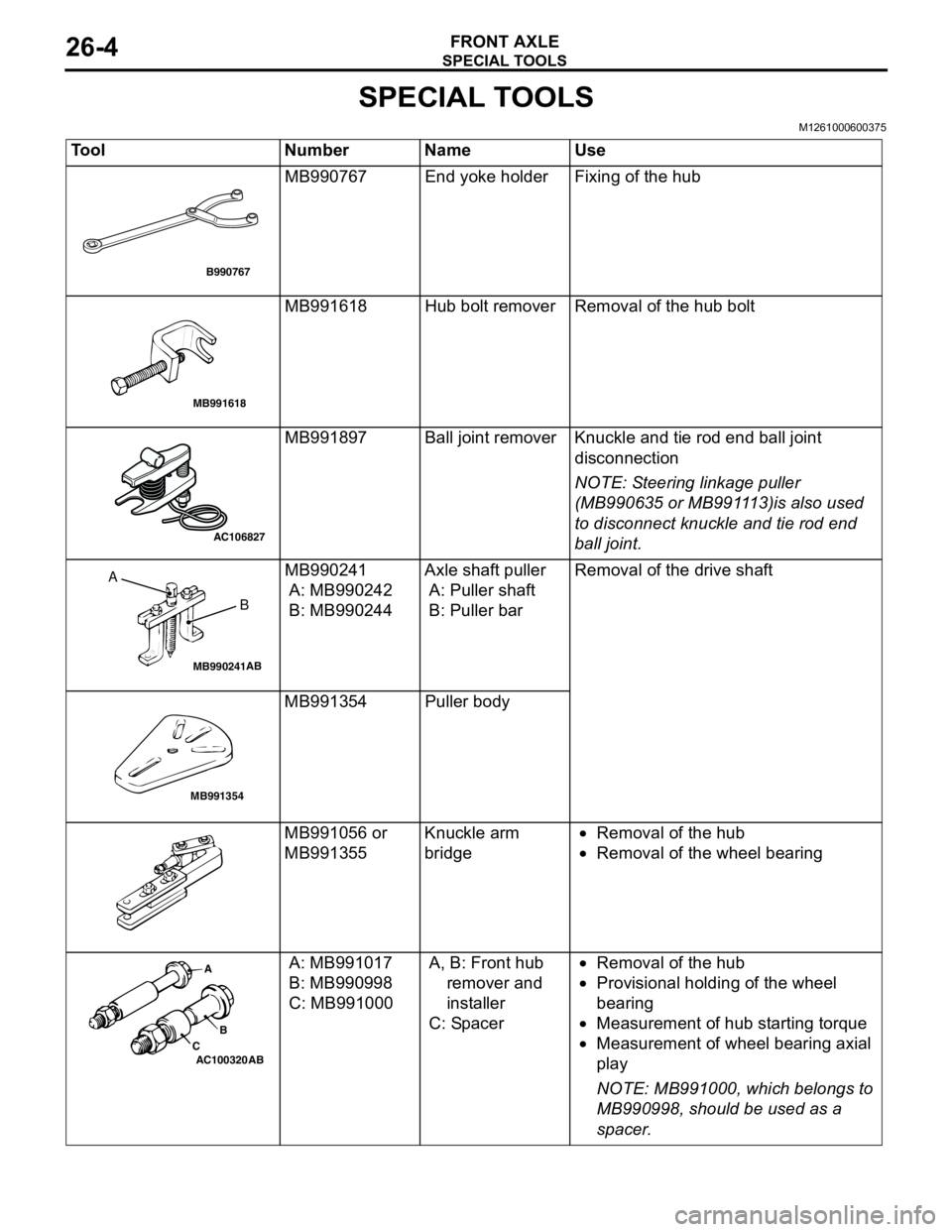
SPECIAL TOOLS
M1261000600375
Tool Number Name Use
MB990767 End yoke holder Fixing of the hub
MB991618 Hub bolt remover Removal of the hub bolt
MB991897 Ball joint remover Knuckle and tie rod end ball joint
disconnection
NOTE: Steering linkage puller
(MB990635 or MB991113)is also used
to disconnect knuckle and tie rod end
ball joint.
MB990241
A: MB990242
B: MB990244Axle shaft puller
A: Puller shaft
B: Puller barRemoval of the drive shaft
MB991354 Puller body
MB991056 or
MB991355Knuckle arm
bridge•Removal of the hub
•Removal of the wheel bearing
A: MB991017
B: MB990998
C: MB991000A, B: Front hub
remover and
installer
C: Spacer•Removal of the hub
•Provisional holding of the wheel
bearing
•Measurement of hub starting torque
•Measurement of wheel bearing axial
play
NOTE: MB991000, which belongs to
MB990998, should be used as a
spacer.
B990767
MB991618
AC106827
MB990241AB
A
B
MB991354
AC100320 ABA
B
C
Page 142 of 788
FRONT AXLE HUB ASSEMBLY
FRONT AXLE26-10
<
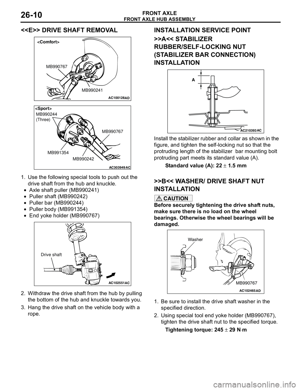
1. Use the following special tools to push out the
drive shaft from the hub and knuckle.
•Axle shaft puller (MB990241)
•Puller shaft (MB990242)
•Puller bar (MB990244)
•Puller body (MB991354)
•End yoke holder (MB990767)
2. Withdraw the drive shaft from the hub by pulling
the bottom of the hub and knuckle towards you.
3. Hang the drive shaft on the vehicle body with a
rope.
INSTALLATION SERVICE POINT
>>A<< STABILIZER
RUBBER/SELF-LOCKING NUT
(STABILIZER BAR CONNECTION)
INSTALLATION
Install the stabilizer rubber and collar as shown in the
figure, and tighten the self-locking nut so that the
protruding length of the stabilizer bar mounting bolt
protruding part meets its standard value (A).
Standard value (A): 22 ± 1.5 mm
>>B<< WASHER/ DRIVE SHAFT NUT
INSTALLATION
CAUTION
Before securely tightening the drive shaft nuts,
make sure there is no load on the wheel
bearings. Otherwise the wheel bearings will be
damaged.
1. Be sure to install the drive shaft washer in the
specified direction.
2. Using special tool end yoke holder (MB990767),
tighten the drive shaft nut to the specified torque.
Tightening torque: 245 ± 29 N⋅m
AC100128
MB990241 MB990767
AD
AC303949
MB990244
(Three)
MB990767
MB990242 MB991354
AC
AC102551
AC
Drive shaft
AC210393AC
A
AC102465AD
MB990767 Washer
Page 147 of 788
Page 166 of 788
TROUBLESHOOTING
WHEEL AND TYRE31-4
WHEEL BALANCE ACCURACYM1311001700247
PURPOSE
This section contains tips and procedures for
achieving accurate wheel balance. Steering wheel
vibration and/or body shake can result if any of these
procedures are not carefully observed.
1. Wheels and tyres must be properly mounted on a
balancer in order to achieve correct balance.
Centring the wheel on the shaft of the balancer is
essential for proper mounting.
2. Off-the-car wheel balancers must be calibrated
periodically to ensure good balancing results. An
inaccurately calibrated balancer could cause
unnecessary replacement of tyres, shocks,
suspension components, or steering components.
Check your balancer's calibration approximately
every 100 balances. Your wheel balancer's
instruction manual should include calibration
procedures. If the calibration procedures specifically
for your balancer are missing, use the generic steps
in this section for zero calibration, static balance, and
dynamic balance checks. The wheel balancer
calibration checks are also described in the
flowchart. (Refer to P.31-6).
PROCEDURE
1. Confirm that the balancer's cone and the wheel
mounting cone are undamaged and free of dirt
and rust.
2. On this vehicle, the wheel's centre hole on the
hub side has a chamfered edge. Use a
back-mounting cone on your wheel balancer to
centre the wheel on the balancer shaft.
3. Install a wheel mounting cone. The appropriate
size cone for this vehicle is 67.0 mm.
4. Before balancing the wheel, remove any wheel
weights from both sides. Also check both sides for
any damage.
5. When installing wheel weights, hammer them at a
straight (not diagonal) angle. Scalloped
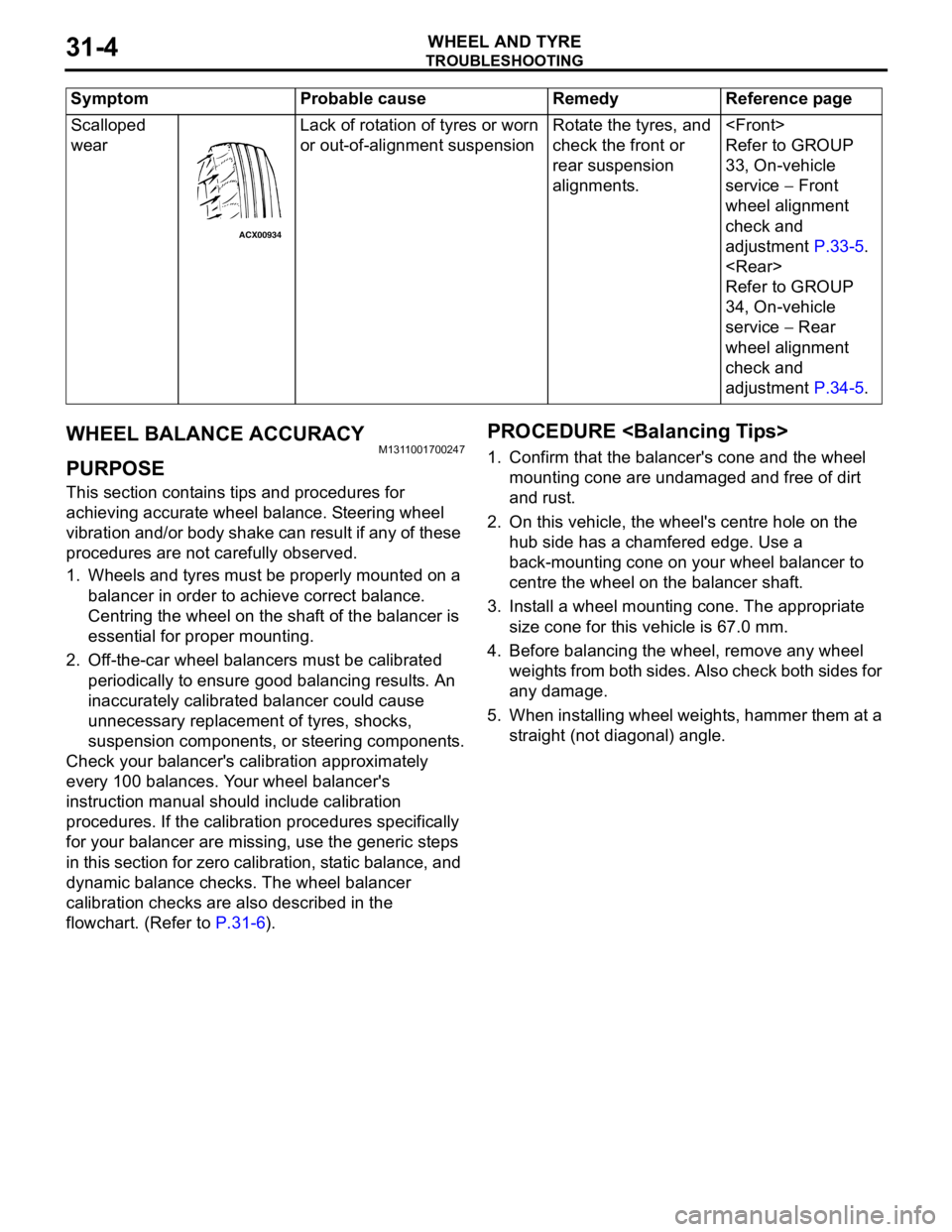
wearLack of rotation of tyres or worn
or out-of-alignment suspensionRotate the tyres, and
check the front or
rear suspension
alignments.
Refer to GROUP
33, On-vehicle
service − Front
wheel alignment
check and
adjustment P.33-5.
Refer to GROUP
34, On-vehicle
service − Rear
wheel alignment
check and
adjustment P.34-5. Symptom Probable cause Remedy Reference page
ACX00934
Page 172 of 788
GENERAL INFORMATION
POWER PLANT MOUNT32-2
GENERAL INFORMATION
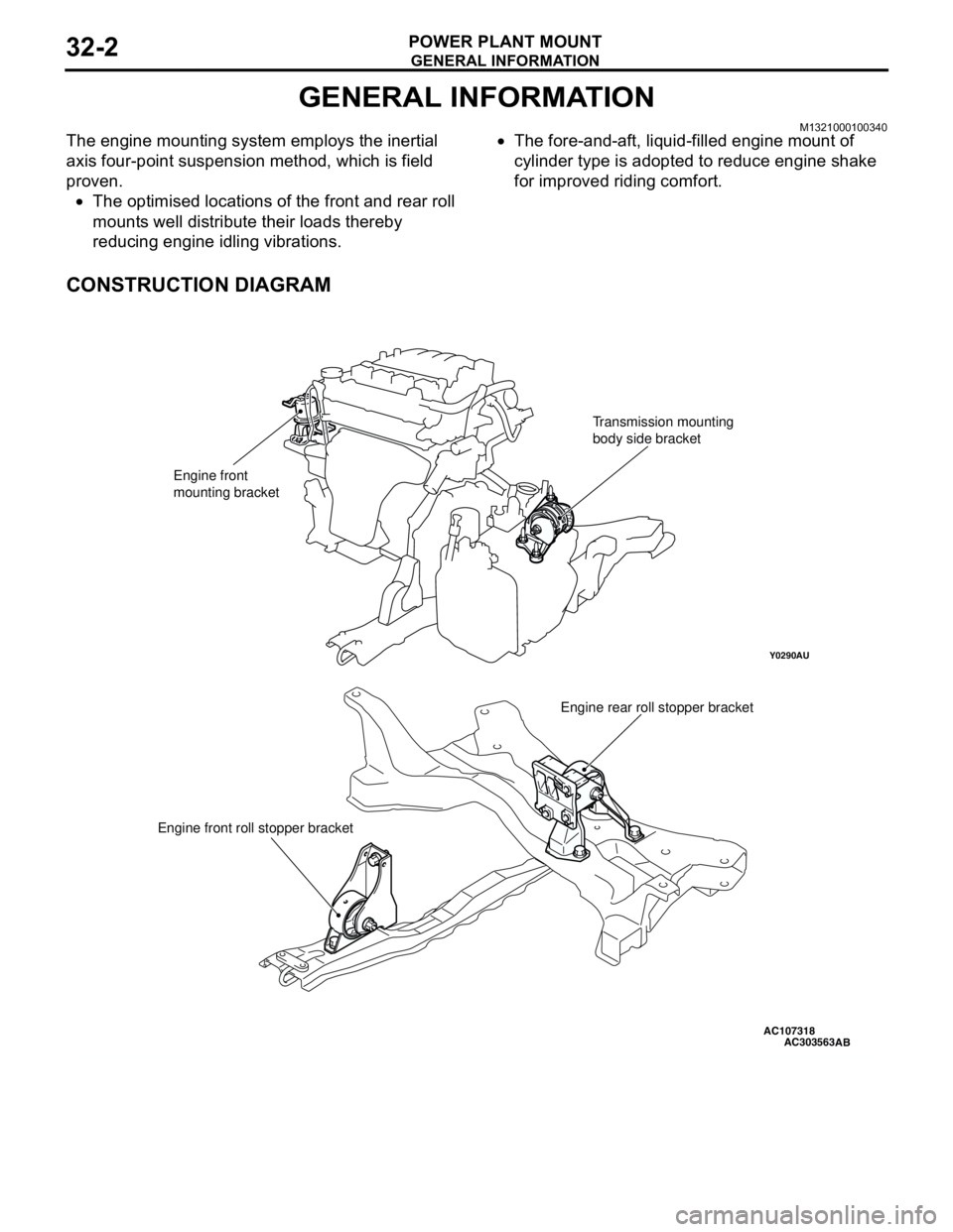
M1321000100340The engine mounting system employs the inertial
axis four-point suspension method, which is field
proven.
•The optimised locations of the front and rear roll
mounts well distribute their loads thereby
reducing engine idling vibrations.•The fore-and-aft, liquid-filled engine mount of
cylinder type is adopted to reduce engine shake
for improved riding comfort.
CONSTRUCTION DIAGRAM
AC107318
Y0290AU
AC303563
Engine front
mounting bracketTransmission mounting
body side bracket
Engine rear roll stopper bracket
Engine front roll stopper bracket
AB