vacuum MITSUBISHI LANCER 2005 Workshop Manual
[x] Cancel search | Manufacturer: MITSUBISHI, Model Year: 2005, Model line: LANCER, Model: MITSUBISHI LANCER 2005Pages: 788, PDF Size: 45.98 MB
Page 57 of 788
INLET MANIFOLD
INTAKE AND EXHAUST15-5
INLET MANIFOLD
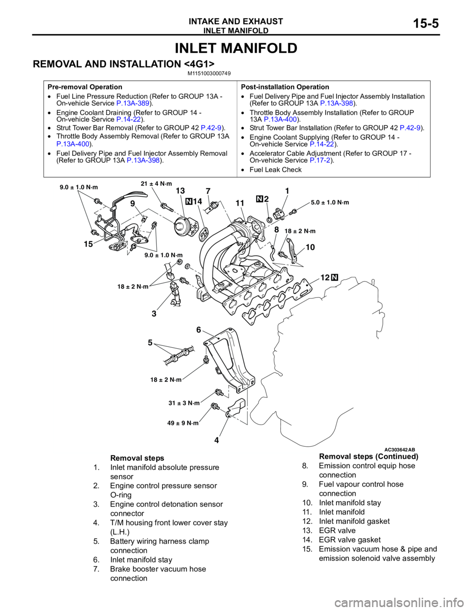
REMOVAL AND INSTALLATION <4G1>M1151003000749
Pre-removal Operation
•Fuel Line Pressure Reduction (Refer to GROUP 13A -
On-vehicle Service P.13A-389).
•Engine Coolant Draining (Refer to GROUP 14 -
On-vehicle Service P.14-22).
•Strut Tower Bar Removal (Refer to GROUP 42 P.42-9).
•Throttle Body Assembly Removal (Refer to GROUP 13A
P.13A-400).
•Fuel Delivery Pipe and Fuel Injector Assembly Removal
(Refer to GROUP 13A P.13A-398).Post-installation Operation
•Fuel Delivery Pipe and Fuel Injector Assembly Installation
(Refer to GROUP 13A P.13A-398).
•Throttle Body Assembly Installation (Refer to GROUP
13A P.13A-400).
•Strut Tower Bar Installation (Refer to GROUP 42 P.42-9).
•Engine Coolant Supplying (Refer to GROUP 14 -
On-vehicle Service P.14-22).
•Accelerator Cable Adjustment (Refer to GROUP 17 -
On-vehicle Service P.17-2).
•Fuel Leak Check
AC303642AB
15
3
6
5
412 10 71
2
11
913
14
21 ± 4 N·m
9.0 ± 1.0 N·m
9.0 ± 1.0 N·m
18 ± 2 N·m
18 ± 2 N·m18 ± 2 N·m5.0 ± 1.0 N·m
31 ± 3 N·m
49 ± 9 N·m
N
N
N
8
Removal steps
1. Inlet manifold absolute pressure
sensor
2. Engine control pressure sensor
O-ring
3. Engine control detonation sensor
connector
4. T/M housing front lower cover stay
(L.H.)
5. Battery wiring harness clamp
connection
6. Inlet manifold stay
7. Brake booster vacuum hose
connection8. Emission control equip hose
connection
9. Fuel vapour control hose
connection
10. Inlet manifold stay
11. Inlet manifold
12. Inlet manifold gasket
13. EGR valve
14. EGR valve gasket
15. Emission vacuum hose & pipe and
emission solenoid valve assembly Removal steps (Continued)
Page 58 of 788
INLET MANIFOLD
INTAKE AND EXHAUST15-6
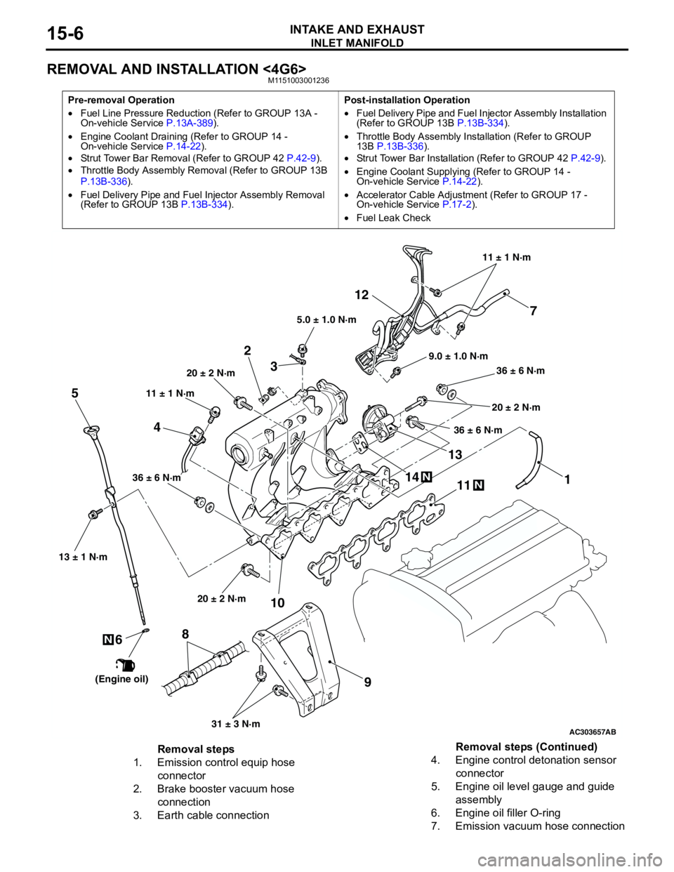
REMOVAL AND INSTALLATION <4G6>M1151003001236
Pre-removal Operation
•Fuel Line Pressure Reduction (Refer to GROUP 13A -
On-vehicle Service P.13A-389).
•Engine Coolant Draining (Refer to GROUP 14 -
On-vehicle Service P.14-22).
•Strut Tower Bar Removal (Refer to GROUP 42 P.42-9).
•Throttle Body Assembly Removal (Refer to GROUP 13B
P.13B-336).
•Fuel Delivery Pipe and Fuel Injector Assembly Removal
(Refer to GROUP 13B P.13B-334).Post-installation Operation
•Fuel Delivery Pipe and Fuel Injector Assembly Installation
(Refer to GROUP 13B P.13B-334).
•Throttle Body Assembly Installation (Refer to GROUP
13B P.13B-336).
•Strut Tower Bar Installation (Refer to GROUP 42 P.42-9).
•Engine Coolant Supplying (Refer to GROUP 14 -
On-vehicle Service P.14-22).
•Accelerator Cable Adjustment (Refer to GROUP 17 -
On-vehicle Service P.17-2).
•Fuel Leak Check
AC303657
9.0 ± 1.0 N·m11 ± 1 N·m
20 ± 2 N·m
31 ± 3 N·m 36 ± 6 N·m
20 ± 2 N·m
20 ± 2 N·m
36 ± 6 N·m
36 ± 6 N·m
11
9 10 212
N1413N
AB
5.0 ± 1.0 N·m
3
1
11 ± 1 N·m
4
N
13 ± 1 N·m
5
6
(Engine oil)
7
8
Removal steps
1. Emission control equip hose
connector
2. Brake booster vacuum hose
connection
3. Earth cable connection4. Engine control detonation sensor
connector
5. Engine oil level gauge and guide
assembly
6. Engine oil filler O-ring
7. Emission vacuum hose connectionRemoval steps (Continued)
Page 59 of 788
EXHAUST MANIFOLD
INTAKE AND EXHAUST15-7
INSPECTIONM1151003100616
Check the following points; replace the part if a
problem is found.
Inlet Manifold Check
1. Check for damage or cracking of any part.2. Clogging of the negative pressure (vacuum) outlet
port, or clogging of the exhaust gas recirculation
passages.
3. Using a straight edge and feeler gauge, check for
distortion of the cylinder head installation surface.
Standard value: 0.15 mm or less
Limit: 0.20 mm
EXHAUST MANIFOLD
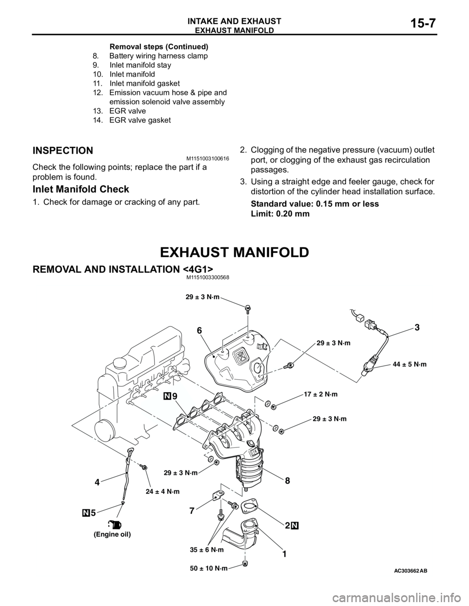
REMOVAL AND INSTALLATION <4G1>M1151003300568
8. Battery wiring harness clamp
9. Inlet manifold stay
10. Inlet manifold
11. Inlet manifold gasket
12. Emission vacuum hose & pipe and
emission solenoid valve assembly
13. EGR valve
14. EGR valve gasketRemoval steps (Continued)
AC30366250 ± 10 N·m 24 ± 4 N·m
35 ± 6 N·m17 ± 2 N·m 29 ± 3 N·m
N
3
7
12 4
N
6
8
44 ± 5 N·m
AB
9
5N
29 ± 3 N·m
29 ± 3 N·m
29 ± 3 N·m
(Engine oil)
Page 109 of 788
17-1
GROUP 17
ENGINE AND
EMISSION
CONTROL
CONTENTS
ENGINE CONTROL . . . . . . . . . .
17-2
GENERAL INFORMATION . . . . . .
17-2
SERVICE SPECIFICATIONS. . . . .17-2
ON-VEHICLE SERVICE. . . . . . . . .17-2
ACCEL CABLE CHECK AND
ADJUSTMENT . . . . . . . . . . . . . . . . . . . . 17-2
ACCELERATOR CABLE AND
PEDAL . . . . . . . . . . . . . . . . . . . . . .
17-3
REMOVAL AND INSTALLATION . . . . . 17-3
EMISSION CONTROL MPI . . . .17-5
GENERAL INFORMATION . . . . . .
17-5
EMISSION CONTROL DEVICE
REFERENCE TABLE . . . . . . . . . .
17-5
SERVICE SPECIFICATION(S) . . .17-5
VACUUM HOSE. . . . . . . . . . . . . . .17-6
VACUUM HOSE PIPING DIAGRAM . . . 17-6
VACUUM CIRCUIT DIAGRAM . . . . . . . 17-7
VACUUM HOSE CHECK. . . . . . . . . . . . 17-8
VACUUM HOSE INSTALLATION . . . . . 17-8
CRANKCASE EMISSION CONTROL
SYSTEM . . . . . . . . . . . . . . . . . . . . .
17-8
GENERAL INFORMATION (CRANKCASE
EMISSION CONTROL SYSTEM) . . . . . 17-8COMPONENT LOCATION (CRANKCASE
EMISSION CONTROL SYSTEM) . . . . . 17-9
POSITIVE CRANKCASE VENTILATION
SYSTEM CHECK . . . . . . . . . . . . . . . . . . 17-9
POSITIVE CRANKCASE VENTILATION
(PCV) VALVE CHECK . . . . . . . . . . . . . . 17-9
EVAPORATIVE EMISSION CONTROL
SYSTEM . . . . . . . . . . . . . . . . . . . . .
17-9
GENERAL INFORMATION (EVAPORATIVE
EMISSION CONTROL SYSTEM) . . . . . 17-9
COMPONENT LOCATION (EVAPORATIVE
EMISSION CONTROL SYSTEM) . . . . . 17-10
PURGE CONTROL SYSTEM CHECK . . 17-10
PURGE PORT VACUUM CHECK . . . . . 17-11
PURGE CONTROL SOLENOID VALVE
CHECK . . . . . . . . . . . . . . . . . . . . . . . . . . 17-11
FUEL VAPOUR CANISTER REMOVAL
AND INSTALLATION . . . . . . . . . . . . . . . 17-12
EXHAUST GAS RECIRCULATION
(EGR) SYSTEM . . . . . . . . . . . . . . .
17-13
GENERAL INFORMATION
(EGR SYSTEM) . . . . . . . . . . . . . . . . . . . 17-13
COMPONENT LOCATION
(EGR SYSTEM) . . . . . . . . . . . . . . . . . . . 17-14
EGR SYSTEM CHECK . . . . . . . . . . . . . 17-15
EGR VALVE CHECK . . . . . . . . . . . . . . . 17-15
EGR PORT VACUUM CHECK <4G1>. . 17-16
EGR CONTROL SOLENOID VALVE
CHECK <4G1> . . . . . . . . . . . . . . . . . . . . 17-16
EGR CONTROL SOLENOID VALVE
CHECK <4G6> . . . . . . . . . . . . . . . . . . . . 17-17
EXHAUST GAS RECIRCULATION (EGR)
VALVE REMOVAL AND
INSTALLATION . . . . . . . . . . . . . . . . . . . 17-18
CATALYTIC CONVERTER . . . . . .17-18
REMOVAL AND INSTALLATION . . . . . . 17-18
Page 114 of 788
EMISSION CONTROL
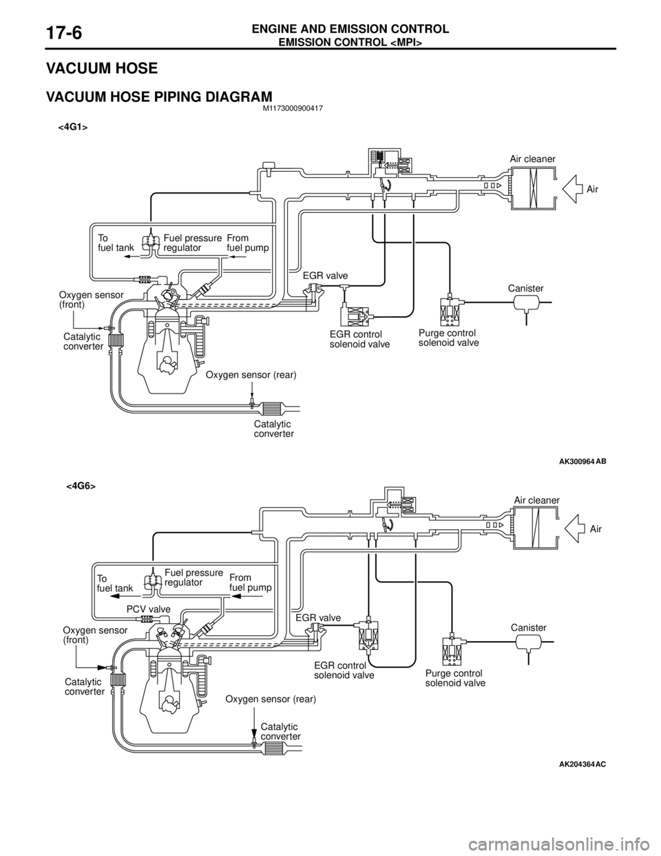
ENGINE AND EMISSION CONTROL17-6
VACUUM HOSE
VACUUM HOSE PIPING DIAGRAMM1173000900417
AK300964
To
fuel tankFuel pressure
regulatorFrom
fuel pump
Catalytic
converter
Catalytic
converter Oxygen sensor
(front)
Oxygen sensor (rear)EGR valve <4G1>
EGR control
solenoid valvePurge control
solenoid valveCanisterAir
AB
Air cleaner
AK204364
AC
Air cleaner
Air
Canister
Purge control
solenoid valve EGR control
solenoid valve EGR valve From
fuel pump To
fuel tankFuel pressure
regulator
PCV valve
Oxygen sensor
(front)
Oxygen sensor (rear) Catalytic
converter
Catalytic
converter
<4G6>
Page 115 of 788
EMISSION CONTROL
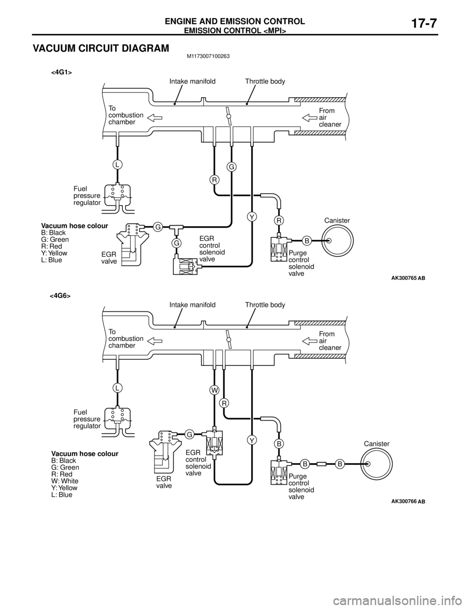
ENGINE AND EMISSION CONTROL17-7
VACUUM CIRCUIT DIAGRAMM1173007100263
AK300765
From
air
cleaner To
combustion
chamberThrottle body
B R
AB
Intake manifold
Y G
G
GR L
Fuel
pressure
regulator
EGR
valveEGR
control
solenoid
valvePurge
control
solenoid
valveCanister
Vacuum hose colour
B: Black
G: Green
R: Red
Y: Yellow
L: Blue
<4G1>
AK300766
From
air
cleaner To
combustion
chamberThrottle body
B B
AB
Intake manifold
Y R
GW L
Fuel
pressure
regulator
EGR
valveEGR
control
solenoid
valve
Purge
control
solenoid
valveCanister
Vacuum hose colour
B: Black
G: Green
R: Red
W: White
Y: Yellow
L: Blue
<4G6>
B
Page 116 of 788
EMISSION CONTROL
ENGINE AND EMISSION CONTROL17-8
VACUUM HOSE CHECKM1173007300159
1. Using the piping diagram as a guide, check to be
sure that the vacuum hoses are correctly
connected.
2. Check the connection condition of the vacuum
hoses, (removed, loose, etc.) and check to be
sure that there are no bends or damage.
VACUUM HOSE INSTALLATIONM1173007200107
1. When connecting the vacuum hoses, they should
be securely inserted onto the nipples.
2. Connect the hoses correctly, using the vacuum
hose piping diagram as a guide.
CRANKCASE EMISSION CONTROL
SYSTEM
GENERAL INFORMATION (CRANKCASE
EMISSION CONTROL SYSTEM)
M1173005000237
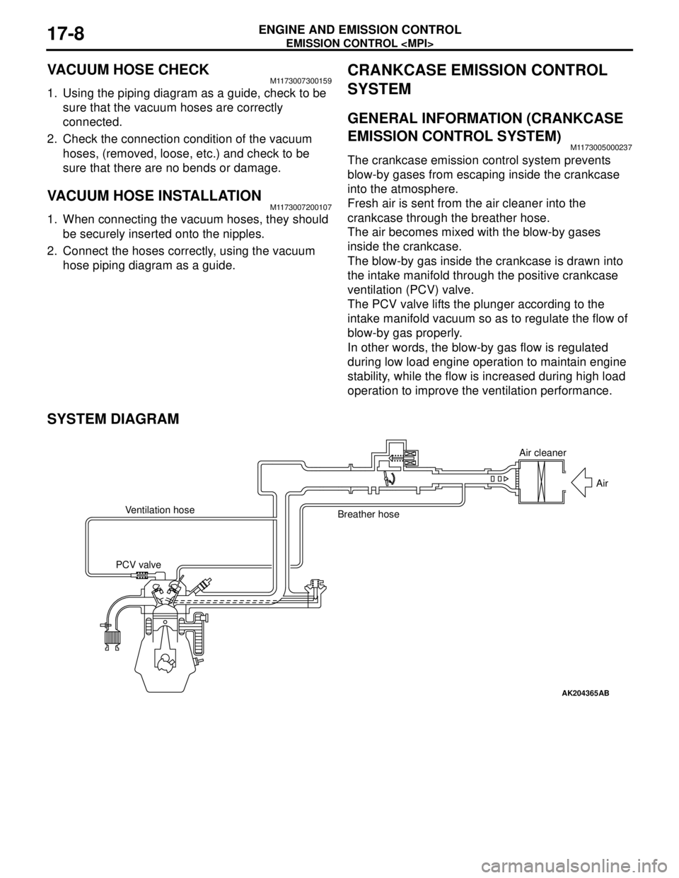
The crankcase emission control system prevents
blow-by gases from escaping inside the crankcase
into the atmosphere.
Fresh air is sent from the air cleaner into the
crankcase through the breather hose.
The air becomes mixed with the blow-by gases
inside the crankcase.
The blow-by gas inside the crankcase is drawn into
the intake manifold through the positive crankcase
ventilation (PCV) valve.
The PCV valve lifts the plunger according to the
intake manifold vacuum so as to regulate the flow of
blow-by gas properly.
In other words, the blow-by gas flow is regulated
during low load engine operation to maintain engine
stability, while the flow is increased during high load
operation to improve the ventilation performance.
SYSTEM DIAGRAM
AK204365
Air cleaner
Air
Ventilation hose
Breather hose
PCV valve
AB
Page 117 of 788
EMISSION CONTROL
ENGINE AND EMISSION CONTROL17-9
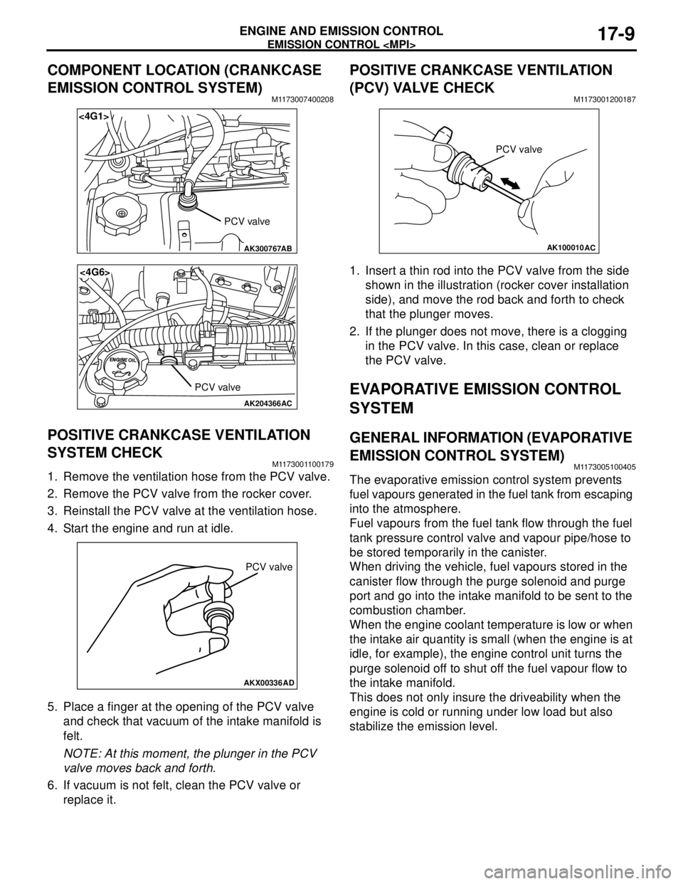
COMPONENT LOCATION (CRANKCASE
EMISSION CONTROL SYSTEM)
M1173007400208
POSITIVE CRANKCASE VENTILATION
SYSTEM CHECK
M1173001100179
1. Remove the ventilation hose from the PCV valve.
2. Remove the PCV valve from the rocker cover.
3. Reinstall the PCV valve at the ventilation hose.
4. Start the engine and run at idle.
5. Place a finger at the opening of the PCV valve
and check that vacuum of the intake manifold is
felt.
NOTE: At this moment, the plunger in the PCV
valve moves back and forth.
6. If vacuum is not felt, clean the PCV valve or
replace it.
POSITIVE CRANKCASE VENTILATION
(PCV) VALVE CHECK
M1173001200187
1. Insert a thin rod into the PCV valve from the side
shown in the illustration (rocker cover installation
side), and move the rod back and forth to check
that the plunger moves.
2. If the plunger does not move, there is a clogging
in the PCV valve. In this case, clean or replace
the PCV valve.
EVAPORATIVE EMISSION CONTROL
SYSTEM
GENERAL INFORMATION (EVAPORATIVE
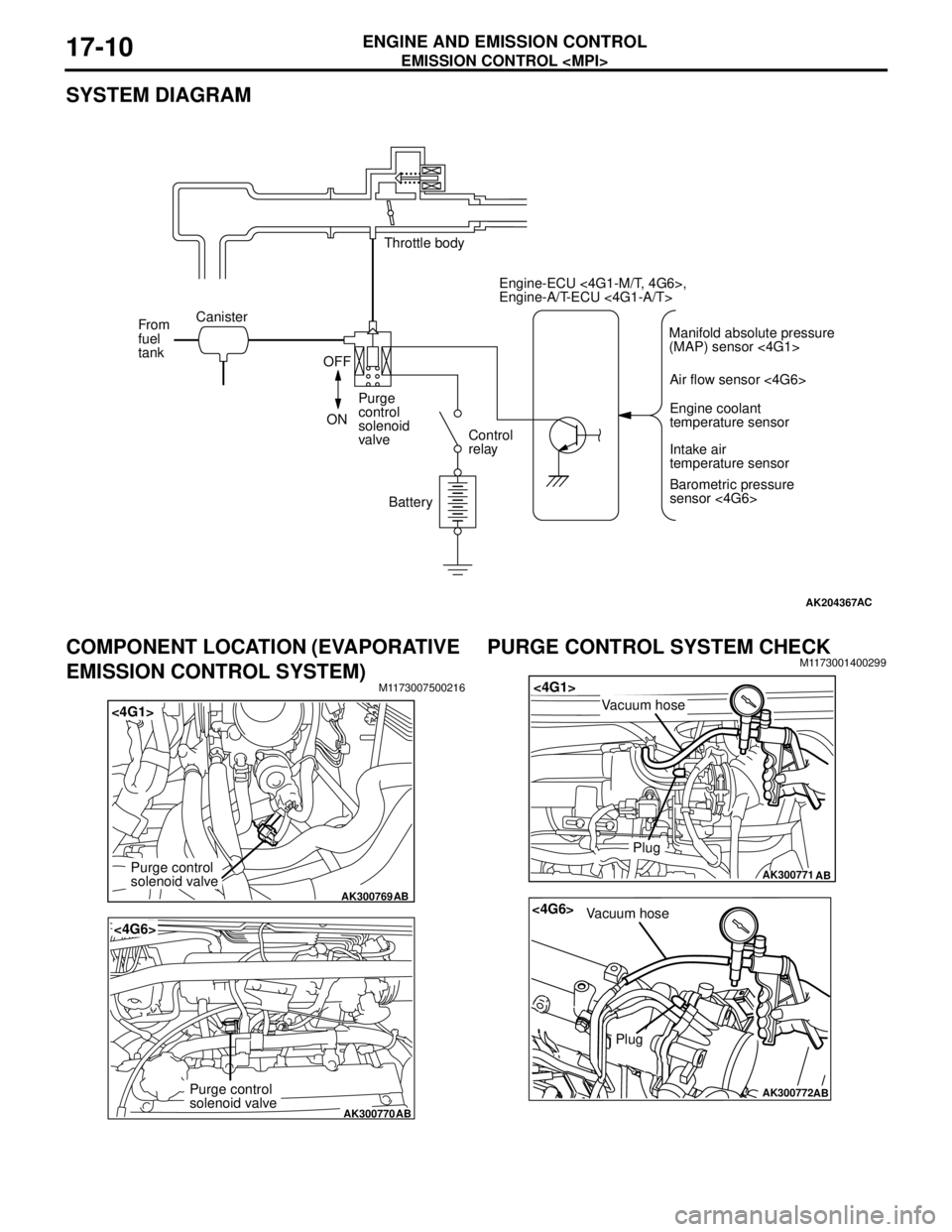
EMISSION CONTROL SYSTEM)
M1173005100405
The evaporative emission control system prevents
fuel vapours generated in the fuel tank from escaping
into the atmosphere.
Fuel vapours from the fuel tank flow through the fuel
tank pressure control valve and vapour pipe/hose to
be stored temporarily in the canister.
When driving the vehicle, fuel vapours stored in the
canister flow through the purge solenoid and purge
port and go into the intake manifold to be sent to the
combustion chamber.
When the engine coolant temperature is low or when
the intake air quantity is small (when the engine is at
idle, for example), the engine control unit turns the
purge solenoid off to shut off the fuel vapour flow to
the intake manifold.
This does not only insure the driveability when the
engine is cold or running under low load but also
stabilize the emission level.
AK300767
<4G1>
AB
PCV valve
AK204366
<4G6>
AC
PCV valve
AKX00336
PCV valve
AD
AK100010
PCV valve
AC
Page 118 of 788
EMISSION CONTROL
ENGINE AND EMISSION CONTROL17-10
SYSTEM DIAGRAM
COMPONENT LOCATION (EVAPORATIVE
EMISSION CONTROL SYSTEM)
M1173007500216
PURGE CONTROL SYSTEM CHECKM1173001400299
AK204367AC
Throttle body
Canister
From
fuel
tank
OFF
ONPurge
control
solenoid
valveControl
relay
BatteryEngine-ECU <4G1-M/T, 4G6>,
Engine-A/T-ECU <4G1-A/T>
Air flow sensor <4G6>
Engine coolant
temperature sensor
Intake air
temperature sensor
Barometric pressure
sensor <4G6> Manifold absolute pressure
(MAP) sensor <4G1>
AK300769
<4G1>
AB
Purge control
solenoid valve
AK300770
<4G6>
AB
Purge control
solenoid valve
AK300771
<4G1>
AB
Plug
Vacuum hose
AK300772
<4G6>
AB
Plug
Vacuum hose
Page 119 of 788
EMISSION CONTROL
ENGINE AND EMISSION CONTROL17-11
1. Disconnect the vacuum hose (red stripe) from
throttle body and connect it to a hand vacuum
pump.
2. Plug the nipple from which the vacuum hose was
removed.
3. When the engine is cold or hot, apply a vacuum of
53 kPa, and check the condition of the vacuum.
When engine is cold
(Engine coolant temperature: 40°C or less)
When engine is hot
(Engine coolant temperature: 80°C or higher)
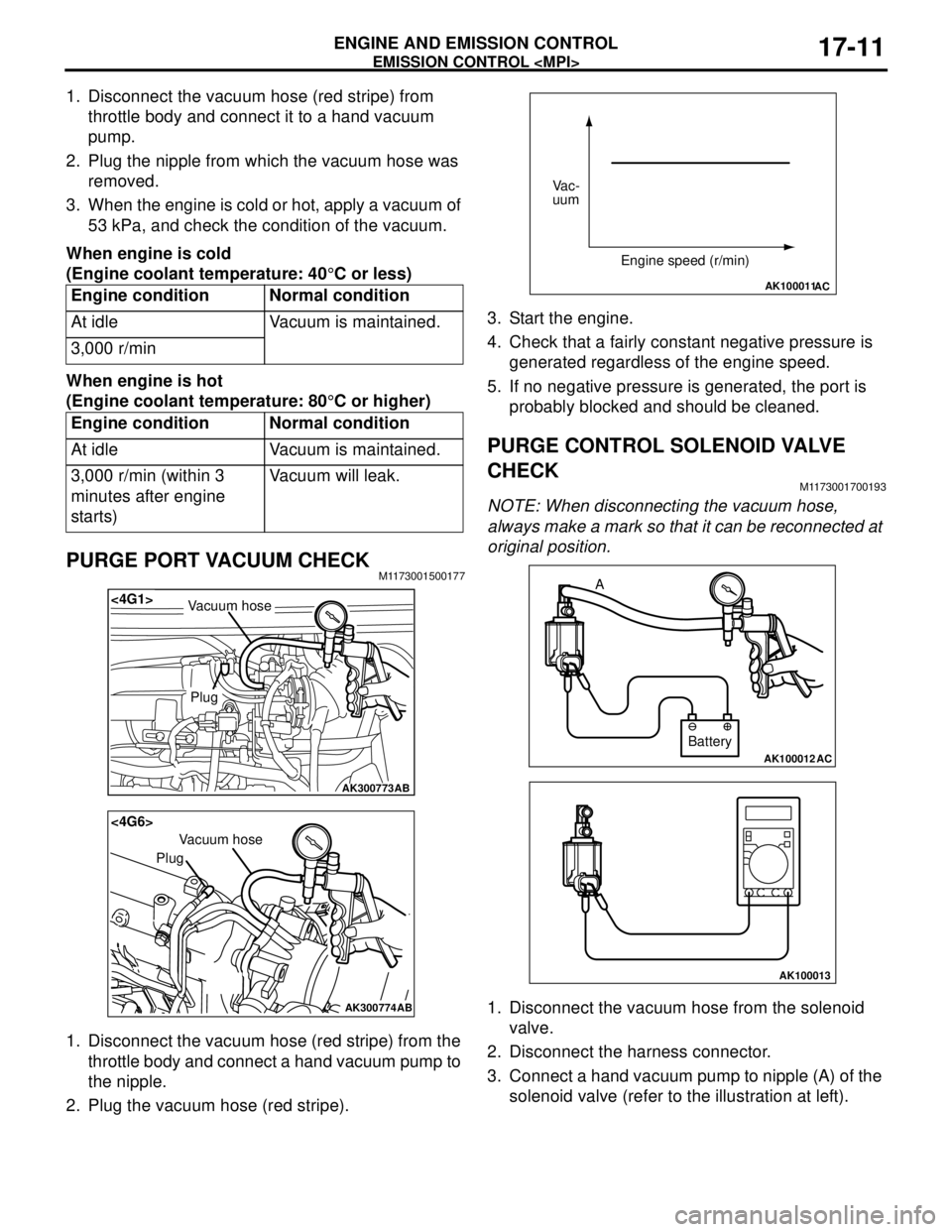
PURGE PORT VACUUM CHECKM1173001500177
1. Disconnect the vacuum hose (red stripe) from the
throttle body and connect a hand vacuum pump to
the nipple.
2. Plug the vacuum hose (red stripe).3. Start the engine.
4. Check that a fairly constant negative pressure is
generated regardless of the engine speed.
5. If no negative pressure is generated, the port is
probably blocked and should be cleaned.
PURGE CONTROL SOLENOID VALVE
CHECK
M1173001700193
NOTE: When disconnecting the vacuum hose,
always make a mark so that it can be reconnected at
original position.
1. Disconnect the vacuum hose from the solenoid
valve.
2. Disconnect the harness connector.
3. Connect a hand vacuum pump to nipple (A) of the
solenoid valve (refer to the illustration at left). Engine condition Normal condition
At idle Vacuum is maintained.
3,000 r/min
Engine condition Normal condition
At idle Vacuum is maintained.
3,000 r/min (within 3
minutes after engine
starts)Vacuum will leak.
AK300773
<4G1>
AB
Plug
Vacuum hose
AK300774
<4G6>
AB
Plug
Vacuum hose
AK100011AC
Vac-
uum
Engine speed (r/min)
AK100012AC
Battery A
AK100013