control MITSUBISHI LANCER 2006 User Guide
[x] Cancel search | Manufacturer: MITSUBISHI, Model Year: 2006, Model line: LANCER, Model: MITSUBISHI LANCER 2006Pages: 800, PDF Size: 45.03 MB
Page 28 of 800
AC303555AB
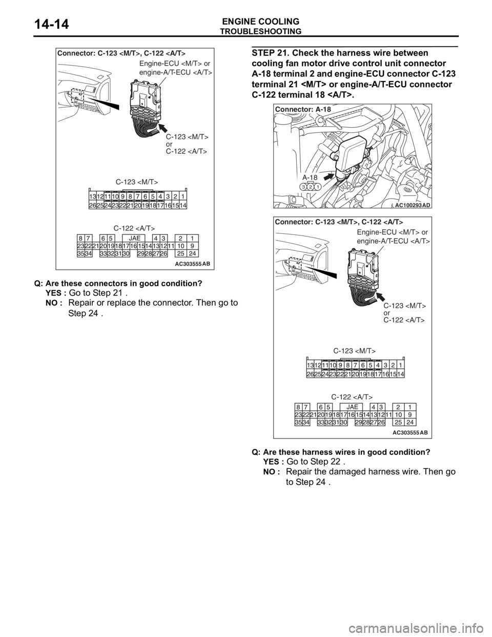
Connector: C-123
or
C-122
C-123
Engine-ECU
engine-A/T-ECU
C-122
TROUBLESH OOTING
ENGINE COOLING14-14
Q: Are t h es e con n ec tor s in go od con d ition?
YES : Go to S t ep 21 .
NO : Repa ir or replace the conne ctor . Th en go to
S
t ep 24
.
ST EP 2 1 . Check t he harness wire b e twe en
cooling f
an motor drive control uni t connec tor
A-1
8 te rm inal 2 an d en gine-ECU c onnec tor C-123
terminal 2
1
C-1
22 termina l 18 .
AC100293
A-18
321
Connector: A-18
AD
AC303555AB
Connector: C-123
C-123
or
C-122
C-123
Engine-ECU
engine-A/T-ECU
C-122
Q: Are t h es e har n es s wires in go od cond it ion?
YES : Go to S t ep 2 2 .
NO : Repa ir the dama ged harness wire. Then go
to S
t ep 2 4
.
Page 29 of 800
TROUBLESHOOTING
ENGINE COOLING14-15
STEP 22. Check the cooling fan motor drive
control unit.
AC303555AB
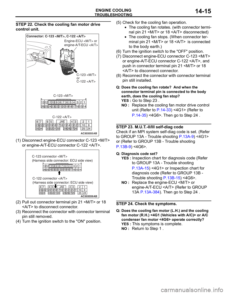
Connector: C-123
or
C-122
C-123
Engine-ECU
engine-A/T-ECU
C-122
(1) D isconn ect e ngin e -ECU conne ctor C-12 3
or e ngine -A/T -ECU conne ctor C-12 2 .
AC303559
C-122 connector
(Harness side connector: ECU side view)
AB
C-123 connector
(Harness side connector: ECU side view)
(2)P ull out conne ctor t e rminal p i n 21
to discon nect conn ector .
(3)R eco nnect t he con necto r with conn ector ter m in al
pin still removed.
(4)T urn t he ig nition switch to the "ON" positio n.
(5)C heck fo r the cooling fan opera t ion.
•The cooling fan ro t a t e s. (with conne ctor termi-
nal pi n 21
•The cooling fan stop s. (When con necto r ter-
minal pi n 21
to the
body earth.)
(6)T urn t he ig nition switch t o the "OFF" po sit i on.
(7)D isconn ect e ngin e -ECU conne ctor C-12 3
or e ngine -A/T -ECU conne ctor C-12 2 , a nd
push in con nect o r terminal pin 21
to discon nect conn ector .
(8)R econnect the con necto r with conn ector te rmin al
pin still inst alled.
Q:Doe s the cooling fa n rot a te ? And wh en th e
c onne ct or te rmin a l p i n is co nnec t e d to t h e bod y
e a rt h, d o es t h e co olin g f a n s t op ?
YES : Go to S t ep 2 3 .
NO : Replac e th e coo lin g fan motor d r ive con t rol
unit (Refer to
P.14-33) <4G1> (Refer to
P.14-35) <4G6>. Then go to S t e p 24 .
STEP 2 3 . M.U.T . -II/III self-dia g code
Check if an MPI system self- d iag code is set. (Ref er
to GROUP
13A - T r ouble shooting
P.13A-9) <4G1>
or (Refer to GROUP 13 B - T r ouble sho o ting
P.13B-9) <4G6>.
Q:Diagn o sis co de se t?
YES : Inspecti on chart fo r dia gnosis code (Re f er
to GROUP 13A - T r ou ble shoot ing
P.13A-15) <4G1 > or Inspection chart for
diagnosis code (Re f er to GROUP 13B -
T
r ouble sh ootin g
P.13B-15) <4G6>.
NO : Replac e th e engine-ECU
engine-A/T
- ECU (Refer to GROUP
13A
P.13A- 384). Then go t o S t ep 24 .
STEP 2 4 . Check t he sym ptoms.
Q:Doe s the cooling fa n moto r ( L .H.) and t h e coo l ing
fa n mo to r ( R .H. ) <4G 1 (V ehicles with A/ C)> or A/C
c onde nse r fa n mo tor <4G6> o p era t e c o rre ct ly ?
YES : This symptoms is comple te.
NO : Return to S t ep 1 .
Page 30 of 800
TROUBLESHOOTING
ENGINE COOLING14-16
INSPECTION PROCEDURE 2: Cooling Fan (L.H.) and Cooling Fan (R.H.) <4G1 (Vehicles with A/C)> or
A/C Condenser Fan <4G6> do not Change Speed or Stop
COOLING FAN (L.H.) AND COOLING FAN
(R.H.) OR A/C CONDENSER FAN DRIVE
CIRCUIT
Refer to P.14-6.
CIRCUIT OPERATION
Refer to P.14-6.
TECHNICAL DESCRIPTION
•If the communication line wiring harness between
the cooling fan motor drive control unit and the
engine-ECU
is open, the cooling fan motor (L.H.) and
the cooling fan motor (R.H.) <4G1 (Vehicles with
A/C)>, or the A/C condenser fan motor <4G6>
rotate to prevent the engine from overheating.
•If the system voltage is continuously supplied to
the cooling fan motor drive control unit by a fan
motor relay malfunction and a short circuit on the
cooling fan motor drive control unit power supply
wiring harness, the cooling fan motor (L.H.) and
the cooling fan motor (R.H.) <4G1 (Vehicles with
A/C)>, or the A/C condenser fan motor <4G6>
rotate.
•The cause could also be a malfunction of the
cooling fan motor (L.H.).
•The cause could also be a malfunction of input
signal from the A/C switch, the water temperature
sensor unit and the vehicle speed sensor
or the output shaft speed sensor to the
engine-ECU
•The cause could also be a malfunction of the
cooling fan motor drive control unit or the
engine-ECU
TROUBLESHOOTING HINTS
•Malfunction of fan control relay
•Malfunction of cooling fan motor (L.H.)
•Malfunction of cooling fan motor drive control unit
•Malfunction of engine-ECU
engine-A/T-ECU
•Damaged wiring harness or connector
DIAGNOSIS
STEP 1. Check the fan control relay.
Refer to P.14-23.
Q: Is the fan control relay in good condition?
YES : Go to Step 2 .
NO : Replace the fan control relay. Then go to
Step 8
.
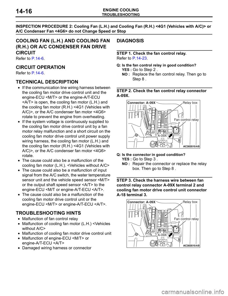
STEP 2. Check the fan control relay connector
A-09X.
AC303510AB
Fan control relay
Relay boxConnector: A-09X
A-09X
Q:Is t h e con n ec tor in goo d c ond it io n?
YES : Go to S t ep 3 .
NO : Repa ir th e con nect o r or rep l ace the re lay
box. Then
go to S t ep 8
.
STEP 3 . Check the harness wire be twee n fan
control relay
connec tor A-0 9 X terminal 2 and
cooling f
an motor drive control uni t connec tor
A-1
8 terminal 3.
AC303510AB
Fan control relay
Relay boxConnector: A-09X
A-09X
Page 31 of 800
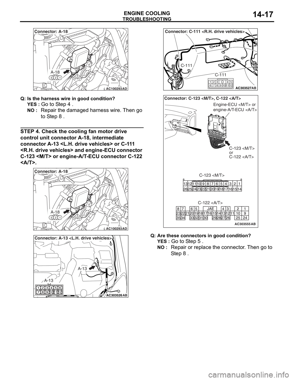
AC100293
A-18
321
Connector: A-18
AD
TROUBLESHOOTING
ENGINE COOLING14-17
Q: Is t h e har n es s wire in good c ondition ?
YES : Go to S t ep 4 .
NO : Repa ir the dama ged harness wire. Then go
to S
t ep 8
.
STEP 4. Ch eck the cooling fan moto r d r iv e
control unit c
onnecto r A-18 , intermed iate
connecto
r A-13
C-1
23
.
AC100293
A-18
321
Connector: A-18
AD
AC303526
Connector: A-13
AB
A-13
A-13
AC303527
Connector: C-111
AB
C-111
C-111
615121179
810234
AC303555AB
Connector: C-123
C-123
or
C-122
C-123
Engine-ECU
engine-A/T-ECU
C-122
Q: Are t h es e con n ec tor s in g ood con d ition?
YES : Go to S t ep 5 .
NO : Repa ir or replace the conne ctor . Th en go to
S
t ep 8
.
Page 32 of 800
TROUBLESHOOTING
ENGINE COOLING14-18
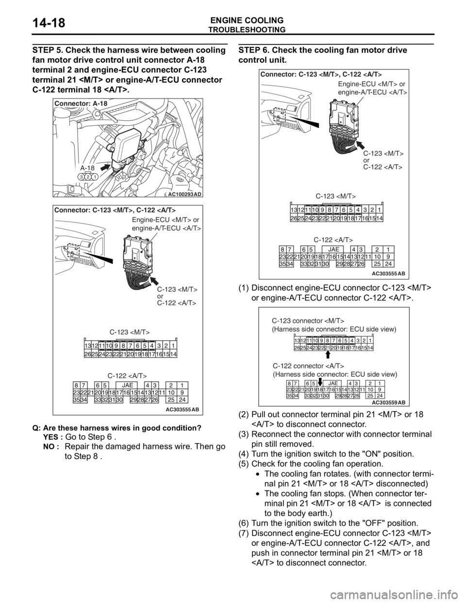
STEP 5. Check the harness wire between cooling
fan motor drive control unit connector A-18
terminal 2 and engine-ECU connector C-123
terminal 21
C-122 terminal 18 .
AC100293
A-18
321
Connector: A-18
AD
AC303555AB
Connector: C-123
or
C-122
C-123
Engine-ECU
engine-A/T-ECU
C-122
Q: Are t h es e har n es s wires in goo d cond it ion?
YES : Go to S t ep 6 .
NO : Repa ir the dama ged harness wire. Then go
to S
t ep 8
.
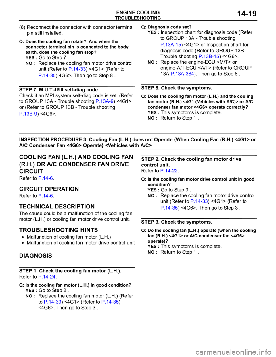
STEP 6 . Check the cooling fan moto r d r iv e
control unit.
AC303555AB
Connector: C-123
C-123
or
C-122
C-123
Engine-ECU
engine-A/T-ECU
C-122
(1) D isconn ect e ngin e -ECU conne ctor C-12 3
or e ngine -A/T -ECU conne ctor C-12 2 .
AC303559
C-122 connector
(Harness side connector: ECU side view)
AB
C-123 connector
(Harness side connector: ECU side view)
(2)P ull out conne ctor terminal p i n 21
to discon nect conn ector .
(3)R econnect the con necto r with conn ector te rmin al
pin still removed.
(4)T urn t he ig nition switch t o the "ON" positio n.
(5)C heck fo r the cooling fan opera t ion.
•The cooling fan ro t a t e s. (with conne ctor termi-
nal pi n 21
•The cooling fan stop s. (When con necto r ter-
minal pi n 21
to the
body earth.)
(6)T urn t he ig nition switch t o the "OFF" po sit i on.
(7)D isconn ect e ngin e -ECU conne ctor C-12 3
or e ngine -A/T -ECU conne ctor C-12 2 , a nd
push in con nect o r terminal pin 21
to discon nect conn ector .
Page 33 of 800
TROUBLESHOOTING
ENGINE COOLING14-19
(8) Reconnect the connector with connector terminal
pin still installed.
Q: Does the cooling fan rotate? And when the
connector terminal pin is connected to the body
earth, does the cooling fan stop?
YES : Go to Step 7 .
NO : Replace the cooling fan motor drive control
unit (Refer to
P.14-33) <4G1> (Refer to
P.14-35) 4G6>. Then go to Step 8 .
STEP 7. M.U.T.-II/III self-diag code
Check if an MPI system self-diag code is set. (Refer
to GROUP 13A - Trouble shooting
P.13A-9) <4G1>
or (Refer to GROUP 13B - Trouble shooting
P.13B-9) <4G6>.
Q: Diagnosis code set?
YES : Inspection chart for diagnosis code (Refer
to GROUP 13A - Trouble shooting
P.13A-15) <4G1> or Inspection chart for
diagnosis code (Refer to GROUP 13B -
Trouble shooting
P.13B-15) <4G6>.
NO : Replace the engine-ECU
engine-A/T-ECU (Refer to GROUP
13A
P.13A-384). Then go to Step 8 .
STEP 8. Check the symptoms.
Q: Does the cooling fan motor (L.H.) and the cooling
fan motor (R.H.) <4G1 (Vehicles with A/C)> or A/C
condenser fan motor <4G6> operate correctly?
YES : This symptoms is complete.
NO : Return to Step 1 .
INSPECTION PROCEDURE 3: Cooling Fan (L.H.) does not Operate {When Cooling Fan (R.H.) <4G1> or
A/C Condenser Fan <4G6> Operate}
COOLING FAN (L.H.) AND COOLING FAN
(R.H.) OR A/C CONDENSER FAN DRIVE
CIRCUIT
Refer to P.14-6.
CIRCUIT OPERATION
Refer to P.14-6.
TECHNICAL DESCRIPTION
The cause could be a malfunction of the cooling fan
motor (L.H.) or cooling fan motor drive control unit.
TROUBLESHOOTING HINTS
•Malfunction of cooling fan motor (L.H.)
•Malfunction of cooling fan motor drive control unit
DIAGNOSIS
STEP 1. Check the cooling fan motor (L.H.).
Refer to P.14-24.
Q: Is the cooling fan motor (L.H.) in good condition?
YES : Go to Step 2 .
NO : Replace the cooling fan motor (L.H.) (Refer
to
P.14-33) <4G1> (Refer to P.14-35)
<4G6>. Then go to Step 3 .
STEP 2. Check the cooling fan motor drive
control unit.
Refer to P.14-22.
Q: Is the cooling fan motor drive control unit in good
condition?
YES : Go to Step 3 .
NO : Replace the cooling fan motor drive control
unit (Refer to
P.14-33) <4G1> (Refer to
P.14-35) <4G6>. Then go to Step 3 .
STEP 3. Check the symptoms.
Q: Do the cooling fan (L.H.) operate (when the cooling
fan (R.H.) <4G1> or A/C condenser fan <4G6>
operate)?
YES : This symptoms is complete.
NO : Return to Step 1 .
Page 34 of 800
TROUBLESHOOTING
ENGINE COOLING14-20
INSPECTION PROCEDURE 4: Cooling Fan (R.H.) <4G1> or A/C Condenser Fan <4G6> does not
Operate {When Cooling Fan (L.H.) Operate}
COOLING FAN (L.H.) AND COOLING FAN
(R.H.) OR A/C CONDENSER FAN DRIVE
CIRCUIT
Refer to P.14-6.
CIRCUIT OPERATION
Refer to P.14-6.
TECHNICAL DESCRIPTION
The cause could be a malfunction of the cooling fan
motor (R.H.) <4G1> or A/C condenser fan motor
<4G6> or cooling fan motor drive control unit.
TROUBLESHOOTING HINTS
•Malfunction of cooling fan motor (R.H.) <4G1> or
A/C condenser fan motor <4G6>
•Malfunction of cooling fan motor drive control unit
DIAGNOSIS
STEP 1. Check the cooling fan motor (R.H.)
<4G1> or A/C condenser fan motor <4G6>.
Cooling fan motor (R.H.) check. (Refer to P.14-24)
<4G1>.
A/C condenser fan motor check. (Refer to GROUP
55
P.55A-91) <4G6>.
Q: Is the cooling fan motor (R.H.) <4G1> or A/C
condenser fan motor <4G6> in good condition?
YES : Go to Step 2 .
NO : Replace the cooling fan motor (R.H.) (Refer
to
P.14-33) <4G1> or A/C condenser fan
motor (Refer to GROUP 55 P.55A-90)
<4G6>. Then go to Step 3 .
STEP 2. Check the cooling fan motor drive
control unit.
Refer to P.14-22.
Q: Is the cooling fan motor drive control unit in good
condition?
YES : Go to Step 3 .
NO : Replace the cooling fan motor drive control
unit (Refer to
P.14-33) <4G1> (Refer to
P.14-35) <4G6>. Then go to Step 3 .
STEP 3. Check the symptoms.
Q: Do the cooling fan (R.H.) <4G1> or A/C condenser
fan <4G6> operate (when the cooling fan (L.H.)
operate)?
YES : This symptoms is complete.
NO : Return to Step 1 .
Page 36 of 800
AC200625
Cylinder block
drain plug
AC
ON-VEHICLE SER VICE
ENGINE COOLING14-22
5.App l y the designa ted sealant to t he scre w area of
th e cylin der block drain plu g , and then tighten to
th e st and ard torq ue.
Sp e c ified s ealant: 3 M Nut Loc king Part
No. 4171 o r e quivale n t
Ti ghtenin g torque:
40 ± 5 N⋅m <4G1>
44 ± 5 N⋅m <4G6>
6.Securely tighten t he drain plug of t he radiator .
7.Reinst all the ra diato r con denser t ank.
CAUTION
Do not use alcohol or methanol anti-freeze or any
engine coolants mixed with alcohol or methanol
anti-freeze. The use of an improper anti-freeze
can cause corrosion of the aluminium compo
-
nents.
AC303612AB
MB991871
AIR HOSE
8. By referring to the section on coolant, select an
appropriate concentration for safe operating
temperature within the range of 30 to 60%. Use
special tool LLC changer (MB991871) to refill the
coolant. A convenient mixture is a 50% water and
50% antifreeze solution (freezing point:
−31°C).
Recommended antifreeze: DIAQUEEN SUPER LONG LIFE COOLANT or equivalent
Quantity:
5.0 L <4G1>
7.0 L <4G6>
NOTE: For how to use special tool MB991871,
refer to its manufacturer’s instructions.
9. Reinstall the radiator cap.
10.Start the engine and let it warm up until the thermostat opens.
11.After repeatedly revving the engine up to 3,000 r/min several times, then stop the engine.
12.Remove the radiator cap after the engine has become cold, and pour in coolant up to the brim.
Reinstall the cap.
CAUTION
Do not overfill the radiator condenser tank.
13.Add coolant to the radiator condenser tank between the "F" and "L" mark if necessary.
CONCENTRATION MEASUREMENT
M1141001100352
Measure the temperature and specific gravity of the
engine coolant to check the antifreeze concentration.
Standard value: 30 − 60% (allowable concentra-
tion range)
Recommended antifreeze: DIAQUEEN SUPER
LONG LIFE COOLANT or equivalent
CAUTION
If the concentration of the anti-freeze is below
30%, the anti-corrosion property will be
adversely affected. In addition, if the concentra
-
tion is above 60%, both the anti-freezing and
engine cooling properties will decrease, affecting
the engine adversely. For these reasons, be sure
to maintain the concentration level within the
specified range.
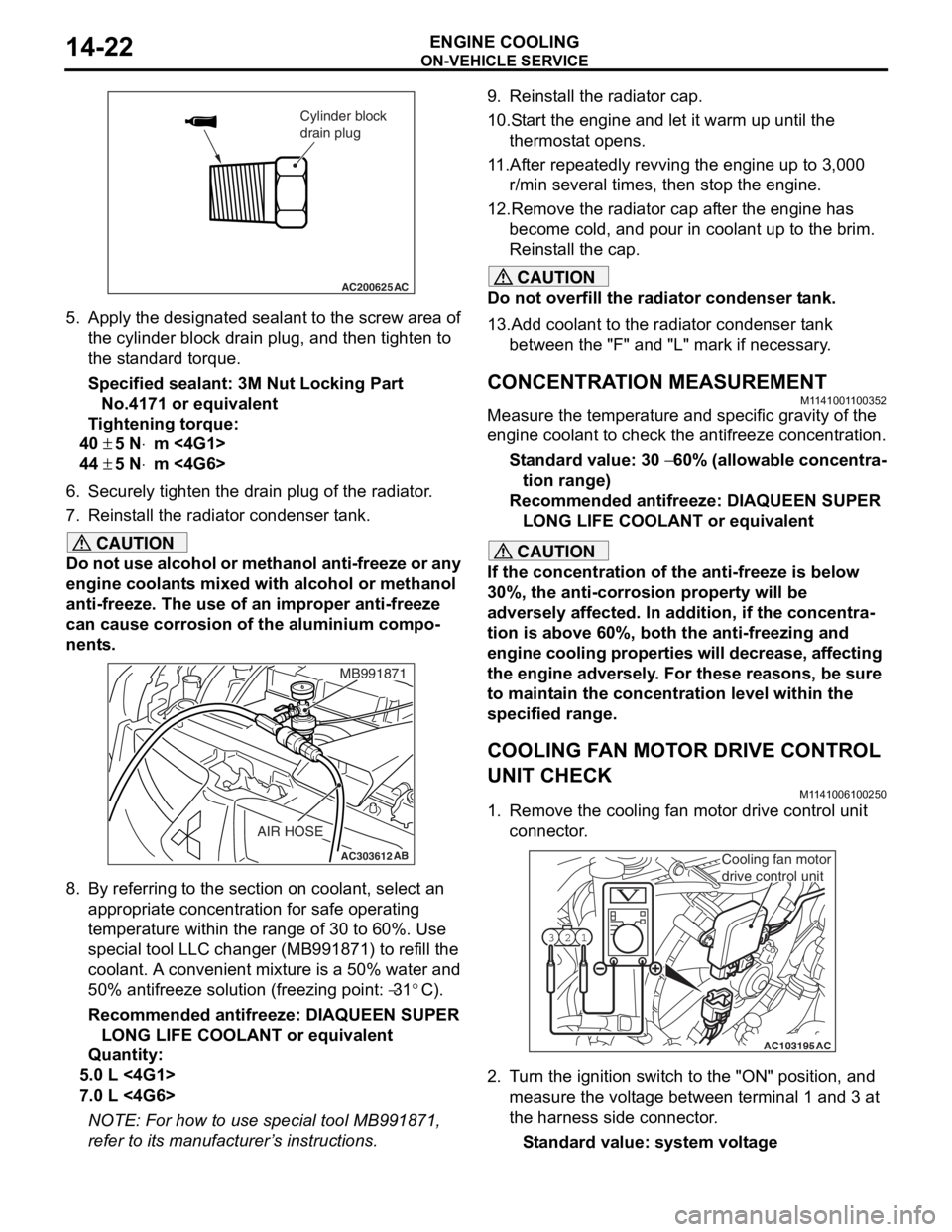
COOLING FAN MOTOR DRIVE CONTROL
UNIT CHECK
M1141006100250
1. Remove the cooling fan motor drive control unit connector.
AC103195
Y1716AU
1
23
AC
Cooling fan motor
drive control unit
2. Turn the ignition switch to the "ON" position, and
measure the voltage between terminal 1 and 3 at
the harness side connector.
Standard value: system voltage
Page 37 of 800
ON-VEHICLE SERVICE
ENGINE COOLING14-23
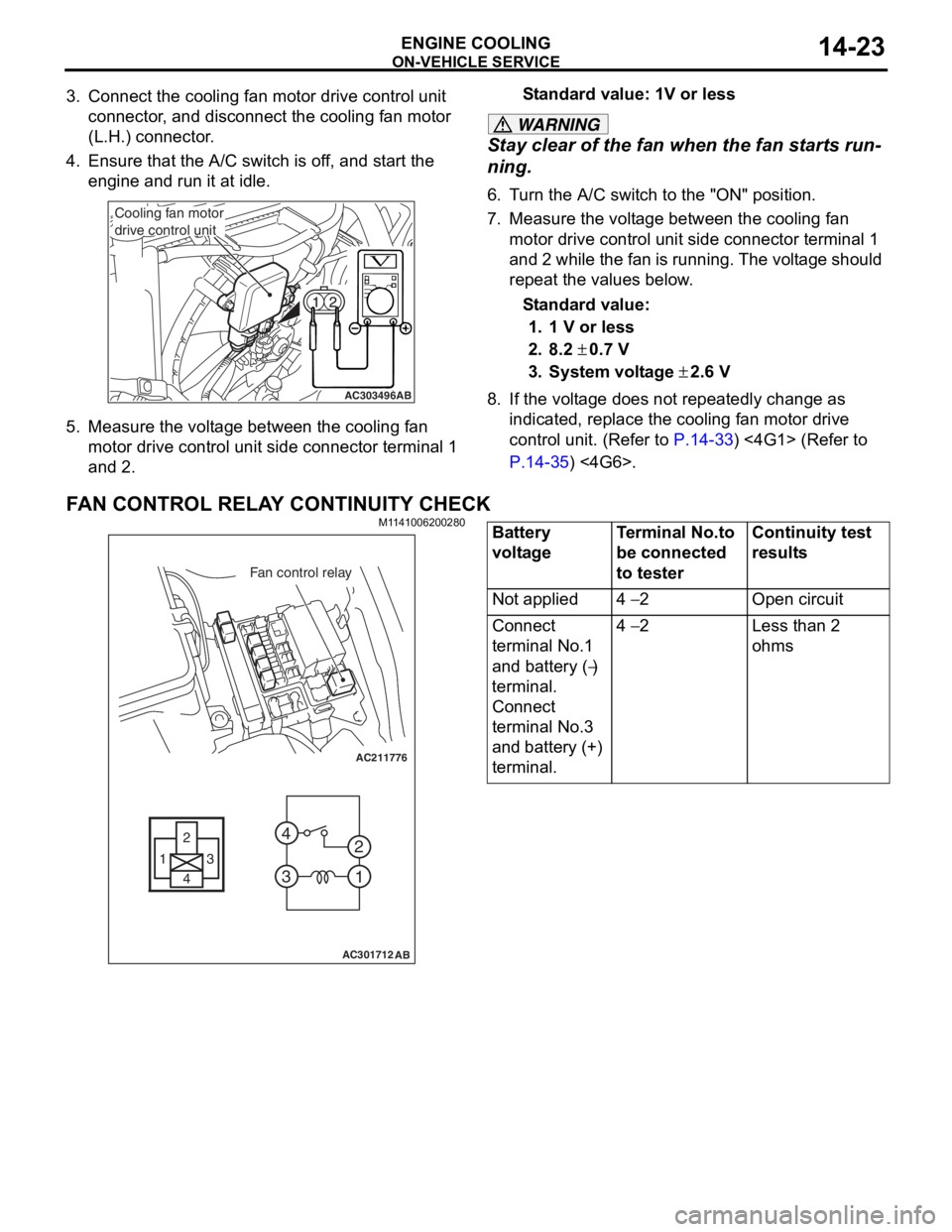
3. Connect the cooling fan motor drive control unit connector, and disconnect the cooling fan motor
(L.H.) connector.
4. Ensure that the A/C switch is off, and start the engine and run it at idle.
AC303496AB
Cooling fan motor
drive control unit
5.Measure the volt ag e betwee n the cooling f an
motor d r ive cont rol un it side conne ctor t e rminal 1
an d 2.
St andard va lue: 1V or le ss
WARNING
Stay clear of the fan when the fan starts run-
ning.
6. Turn the A/C switch to the "ON" position.
7. Measure the voltage between the cooling fan
motor drive control unit side connector terminal 1
and 2 while the fan is running. The voltage should
repeat the values below.
Standard value:
1. 1 V or less
2. 8.2 ± 0.7 V
3. System voltage ± 2.6 V
8. If the voltage does not repeatedly change as indicated, replace the cooling fan motor drive
control unit. (Refer to
P.14-33) <4G1> (Refer to
P.14-35) <4G6>.
FAN CONTROL RELAY CONTINUITY CHECK
M1141006200280
AC211776
13
4 2
3 4
1
2
AC301712
Fan control relay
AB
Battery
voltageTerminal No.to
be connected
to testerContinuity test
results
Not applied4 − 2Open circuit
Connect
terminal No.1
and battery (
−)
terminal.
Connect
terminal No.3
and battery (+)
terminal.
4 − 2Less than 2
ohms
Page 38 of 800
THERMOSTAT
ENGINE COOLING14-24
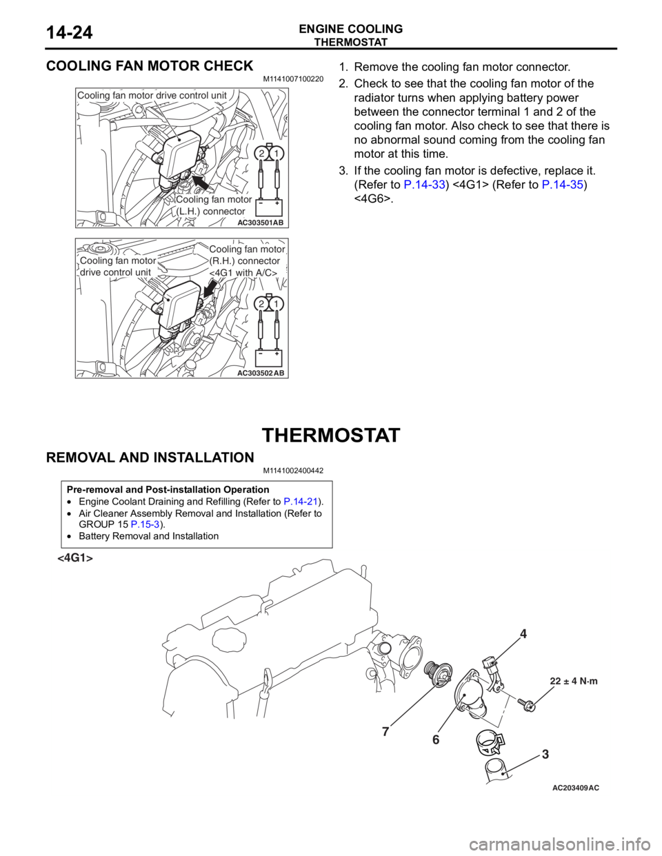
COOLING FAN MOTOR CHECK
M1141007100220
1
2
AC303501AB
Cooling fan motor drive control unit
Cooling fan motor
(L.H.) connector
1
2
AC303502AB
Cooling fan motor
drive control unit
Cooling fan motor
(R.H.) connector
<4G1 with A/C>
1. Remove the cooling fa n mot o r co nnector .
2.Check t o see that t he co oling fan motor of the
ra diato r turns wh en ap plying b a ttery power
b e tween th e con nect o r terminal 1 and 2 of t he
cooling fa n mo tor . Also ch eck to see tha t there is
n o abno rmal soun d co min g from the cooling fa n
motor a t this time.
3.If the cooling fan moto r is defective, replace it.
(Refe r to
P.14-33) <4G1> (Refer to P.14-35)
<4G6>.
THERMOSTA T
REMOVA L AND INST ALLA TION
M1141 0024 0044 2
Pre-removal and Post-installation Operation
•Engine Coolant Draining and Refilling (Refer to P.14-21).
•Air Cleaner Assembly Removal and Installation (Refer to
GROUP 15
P.15-3).
•Battery Removal and Installation
AC203409AC
4
3
6
7
22 ± 4 N·m
<4G1>