control MITSUBISHI LANCER 2006 Owner's Guide
[x] Cancel search | Manufacturer: MITSUBISHI, Model Year: 2006, Model line: LANCER, Model: MITSUBISHI LANCER 2006Pages: 800, PDF Size: 45.03 MB
Page 60 of 800
Page 61 of 800
AC303695AC
1
3
50 ± 10 N·m
2
7
N
N
45
8 4
N9
10
59 ± 10 N·m
45 ± 5 N·m
13 ± 2 N·m
45 ± 5 N·m
13 ± 2 N·m
10
<4G6-M/T>
AC504798AB
<4G6-A/T> 1
2
3N
4
7N8
N9
10
13 ± 2 N·m
13 ± 2 N·m
45 ± 5 N·m
59 ± 10 N·m
6N
10
4
50 ± 10 N·m
13 ± 2 N·m
13 ± 2 N·m
50 ± 10 N·m
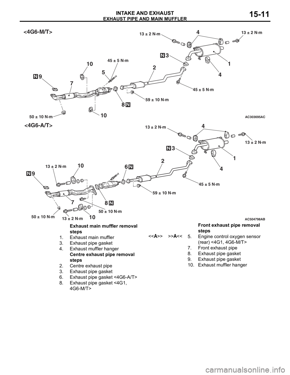
Exhaust main muffler removal
steps
1.Exhaust main muffler
3.Exhaust pipe gasket
4.Exhaust muffler hanger
Centre exhaust pipe removal
steps
2.Centre exhaust pipe
3.Exhaust pipe gasket
6.Exhaust pipe gasket <4G6-A/T>
8.Exhaust pipe gasket <4G1,
4G6-M/T>
Front exhaust pipe removal
steps
<>>>A<<5.Engine control oxygen sensor
(rear) <4G1, 4G6-M/T>
7.Front exhaust pipe
8.Exhaust pipe gasket
9.Exhaust pipe gasket
10.Exhaust muffler hanger
EX HAUS T PIPE AND MAIN MU FFLER
INTAKE AN D EXHAU ST15-11
Page 62 of 800
EXHAUST PIPE AND MAIN MUFFLER
INTAKE AND EXHAUST15-12
REMOVAL SERVICE POINT
<> ENGINE CONTROL OXYGEN SEN-
SOR (REAR) REMOVAL
AC212566AD
MD998770
Engine control
oxygen sensor
(rear)
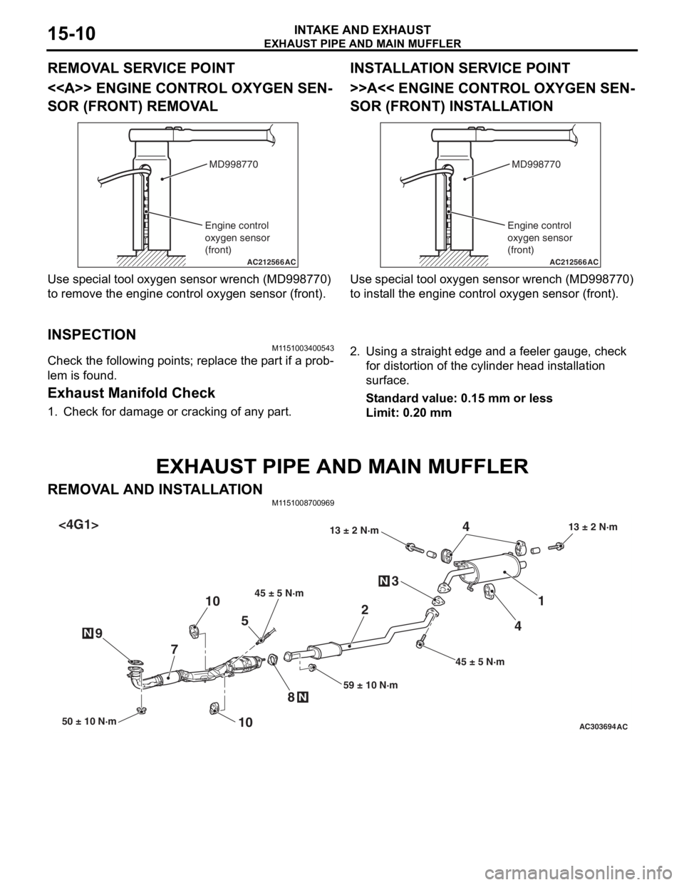
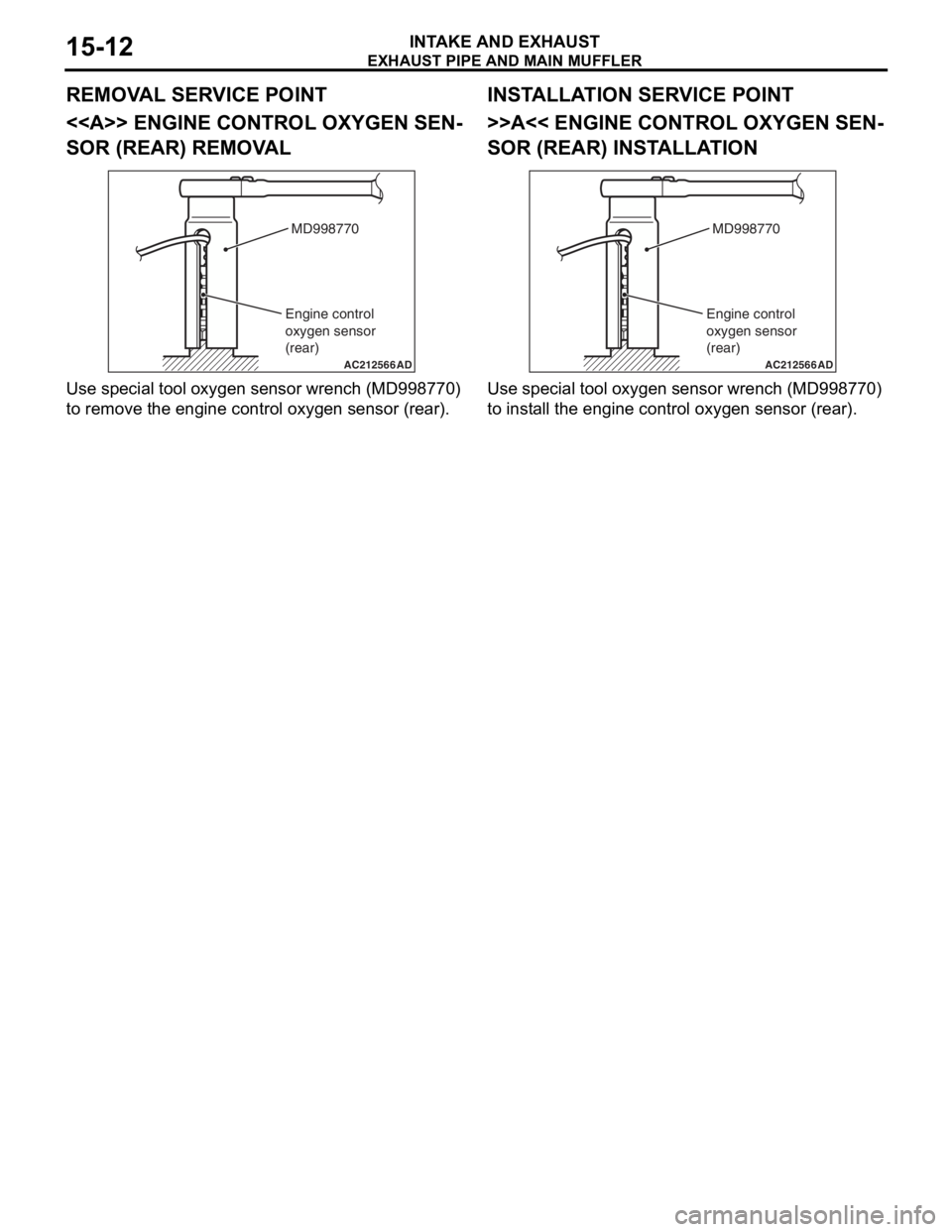
Use spe c ia l tool oxyg en sen s or wrench (MD9987 70)
to remove t
he eng ine contro l oxygen sen s or (re ar).
INSTALLA T ION SER VICE POINT
>>A<< ENGINE CONT ROL OXYGEN SEN-
SOR (REAR) INSTALLA TION
AC212566AD
MD998770
Engine control
oxygen sensor
(rear)
Use spe c ia l tool oxyg en sen s or wrench (MD9987 70)
to inst
all the eng ine contro l oxyge n sen s or (re ar).
Page 92 of 800
IGNITION SYSTEM
ENGINE ELECTRICAL16-30
IGNITION SYSTEM
GENERAL INFORMATIONM1163000100294
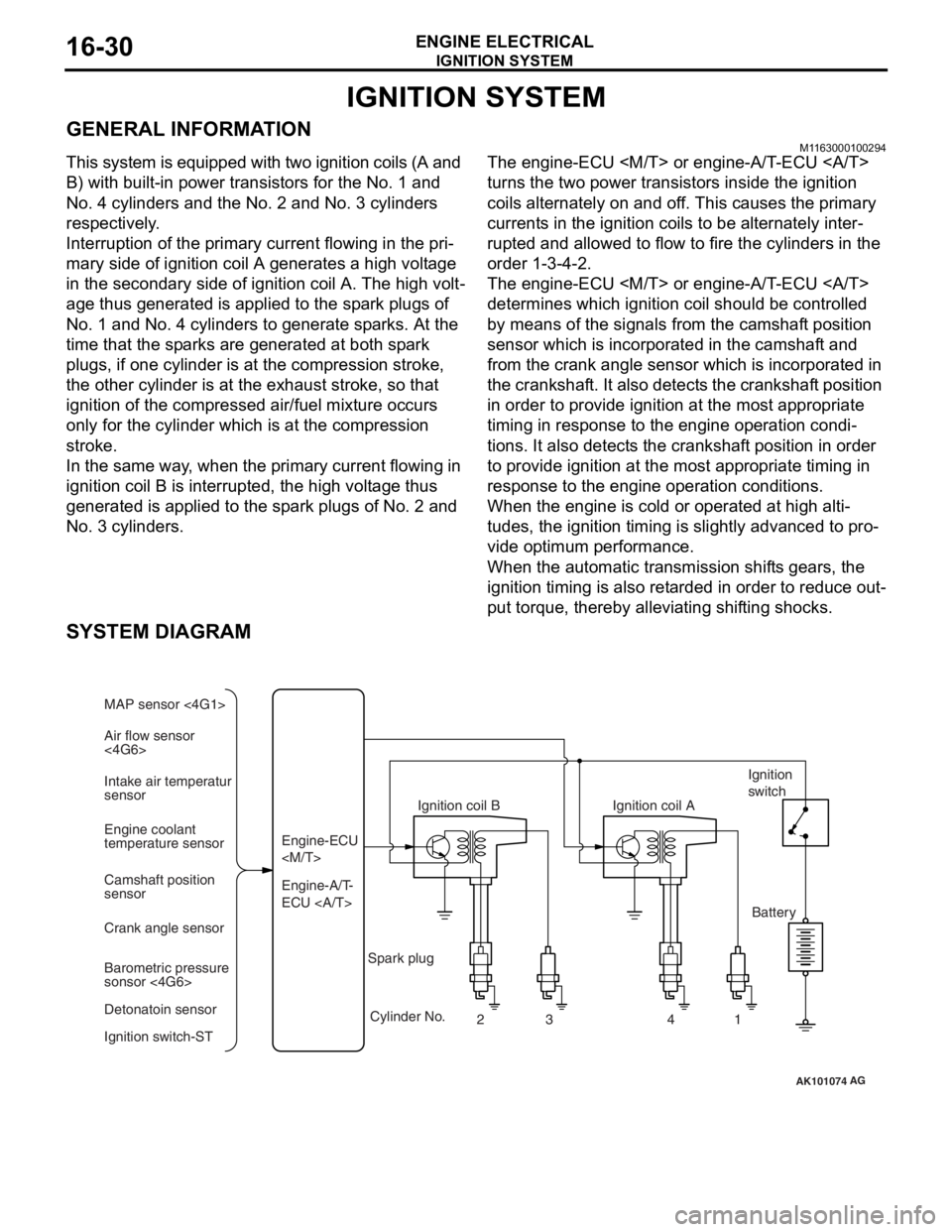
This system is equipped with two ignition coils (A and
B) with built-in power transistors for the No. 1 and
No. 4 cylinders and the No. 2 and No. 3 cylinders
respectively.
Interruption of the primary current flowing in the pri-
mary side of ignition coil A generates a high voltage
in the secondary side of ignition coil A. The high volt
-
age thus generated is applied to the spark plugs of
No. 1 and No. 4 cylinders to generate sparks. At the
time that the sparks are generated at both spark
plugs, if one cylinder is at the compression stroke,
the other cylinder is at the exhaust stroke, so that
ignition of the compressed air/fuel mixture occurs
only for the cylinder which is at the compression
stroke.
In the same way, when the primary current flowing in
ignition coil B is interrupted, the high voltage thus
generated is applied to the spark plugs of No. 2 and
No. 3 cylinders.
The engine-ECU
turns the two power transistors inside the ignition
coils alternately on and off. This causes the primary
currents in the ignition coils to be alternately inter
-
rupted and allowed to flow to fire the cylinders in the
order 1-3-4-2.
The engine-ECU
determines which ignition coil should be controlled
by means of the signals from the camshaft position
sensor which is incorporated in the camshaft and
from the crank angle sensor which is incorporated in
the crankshaft. It also detects the crankshaft position
in order to provide ignition at the most appropriate
timing in response to the engine operation condi
-
tions. It also detects the crankshaft position in order
to provide ignition at the most appropriate timing in
response to the engine operation conditions.
When the engine is cold or operated at high alti-
tudes, the ignition timing is slightly advanced to pro-
vide optimum performance.
When the automatic transmission shifts gears, the
ignition timing is also retarded in order to reduce out
-
put torque, thereby alleviating shifting shocks.
SYSTEM DIAGRAM
AK101074
Air flow sensor
<4G6> MAP sensor <4G1>
Intake air temperatur
sensor
Engine coolant
temperature sensor
Camshaft position
sensor
Crank angle sensor
Barometric pressure
sonsor <4G6>
Detonatoin sensor
Ignition switch-ST Engine-A/T-
ECU Engine-ECU
Ignition coil B
Cylinder No. 23 4
AG
1
Spark plug Ignition coil A
Ignition
switch
Battery
Page 105 of 800
IGNITION SYSTEM
ENGINE ELECTRICAL16-43
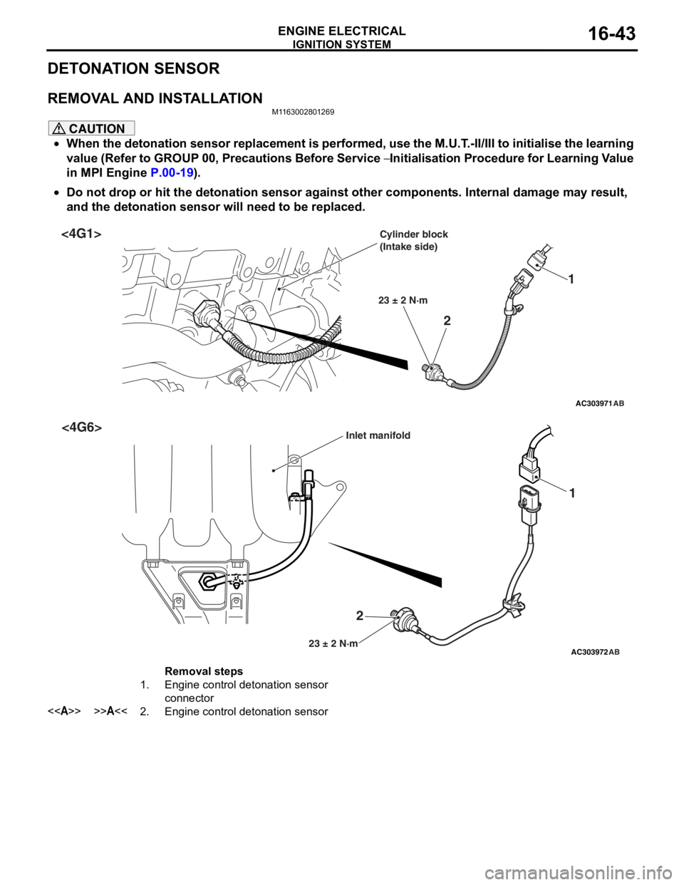
DETONATION SENSOR
REMOVAL AND INSTALLATION
M1163002801269
CAUTION
•When the detonation sensor replacement is performed, use the M.U.T.-II/III to initialise the learning
value (Refer to GROUP 00, Precautions Before Service
− Initialisation Procedure for Learning Value
in MPI Engine
P.00-19).
•
AC303971
2 1
23 ± 2 N·m
AB
<4G1>Cylinder block
(Intake side)
AC303972
2 1
23 ± 2 N·mAB
<4G6>Inlet manifold
Removal steps
1.Engine control detonation sensor
connector
<>>>A<<2.Engine control detonation sensor
Do not drop or hit the detonation sensor against other components. Internal damage may result,
and the detonation sensor will need to be replaced.
Page 106 of 800
IGNITION SYSTEM
ENGINE ELECTRICAL16-44
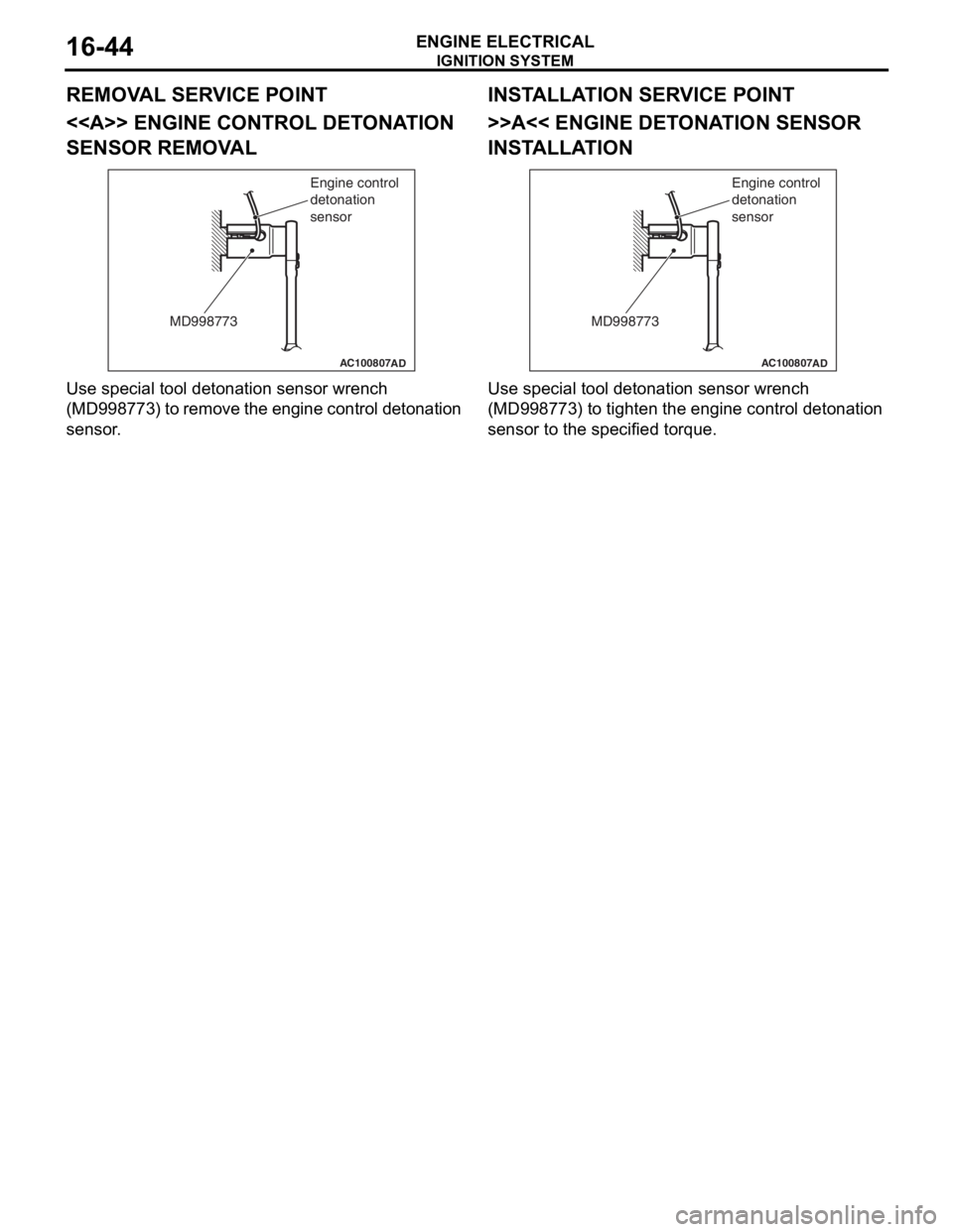
REMOVAL SERVICE POINT
<> ENGINE CONTROL DETONATION
SENSOR REMOVAL
AC100807
MD998773Engine control
detonation
sensor
AD
Use sp
ecial to ol de tonation senso r wrench
(MD9987
73) to remove the engine con t rol det onation
sensor
.
INSTALLA T ION SER VICE POINT
>>A<< ENGINE DETO NA TION SENSOR
INST
ALLA TION
AC100807
MD998773 Engine control
detonation
sensor
AD
Use special to
ol de tonation senso r wrench
(MD9987
73) t o tighten the engine contr o l detona tion
sensor to
the specified torque.
Page 107 of 800
17-1
GROUP 17
ENGINE AND
EMISSION
CONTROL
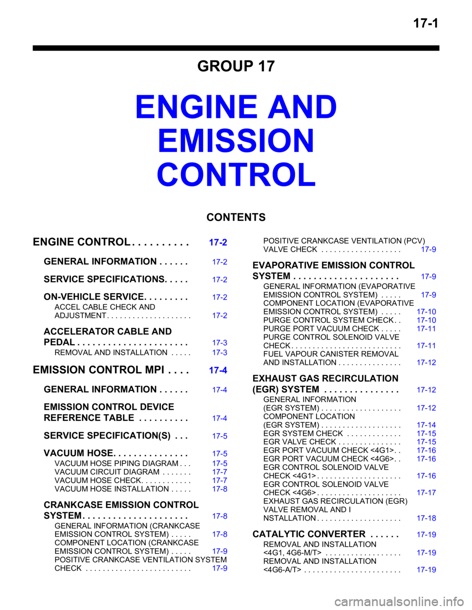
CONTENTS
ENGINE CONTROL . . . . . . . . . .17-2
GENERAL INFORMATION . . . . . .17-2
SERVICE SPECIFICATIONS. . . . .17-2
ON-VEHICLE SERVICE. . . . . . . . .17-2
ACCEL CABLE CHECK AND
ADJUSTMENT . . . . . . . . . . . . . . . . . . . . 17-2
ACCELERATOR CABLE AND
PEDAL . . . . . . . . . . . . . . . . . . . . . .17-3
REMOVAL AND INSTALLATION . . . . . 17-3
EMISSION CONTROL MPI . . . .17-4
GENERAL INFORMATION . . . . . .17-4
EMISSION CONTROL DEVICE
REFERENCE TABLE . . . . . . . . . .17-4
SERVICE SPECIFICATION(S) . . .17-5
VACUUM HOSE. . . . . . . . . . . . . . .17-5
VACUUM HOSE PIPING DIAGRAM . . . 17-5
VACUUM CIRCUIT DIAGRAM . . . . . . . 17-7
VACUUM HOSE CHECK. . . . . . . . . . . . 17-7
VACUUM HOSE INSTALLATION . . . . . 17-8
CRANKCASE EMISSION CONTROL
SYSTEM . . . . . . . . . . . . . . . . . . . . .17-8
GENERAL INFORMATION (CRANKCASE
EMISSION CONTROL SYSTEM) . . . . . 17-8
COMPONENT LOCATI ON (CRANKCASE
EMISSION CONTROL SYSTEM) . . . . . 17-9
POSITIVE CRANKCASE VENTILATION SYSTEM
CHECK . . . . . . . . . . . . . . . . . . . . . . . . . 17-9
POSITIVE CRANKCASE VENTILATION (PCV)
VALVE CHECK . . . . . . . . . . . . . . . . . . . 17-9
EVAPORATIVE EMISSION CONTROL
SYSTEM . . . . . . . . . . . . . . . . . . . . .17-9
GENERAL INFORMATION (EVAPORATIVE
EMISSION CONTROL SYSTEM) . . . . . 17-9
COMPONENT LOCATION (EVAPORATIVE
EMISSION CONTROL SYSTEM) . . . . . 17-10
PURGE CONTROL SYSTEM CHECK . . 17-10
PURGE PORT VACUUM CHECK . . . . . 17-11
PURGE CONTROL SOLENOID VALVE
CHECK . . . . . . . . . . . . . . . . . . . . . . . . . . 17-11
FUEL VAPOUR CANISTER REMOVAL
AND INSTALLATION . . . . . . . . . . . . . . . 17-12
EXHAUST GAS RECIRCULATION
(EGR) SYSTEM . . . . . . . . . . . . . . .17-12
GENERAL INFORMATION
(EGR SYSTEM) . . . . . . . . . . . . . . . . . . . 17-12
COMPONENT LOCATION
(EGR SYSTEM) . . . . . . . . . . . . . . . . . . . 17-14
EGR SYSTEM CHECK . . . . . . . . . . . . . 17-15
EGR VALVE CHECK . . . . . . . . . . . . . . . 17-15
EGR PORT VACUUM CHECK <4G1>. . 17-16
EGR PORT VACUUM CHECK <4G6>. . 17-16
EGR CONTROL SOLENOID VALVE
CHECK <4G1> . . . . . . . . . . . . . . . . . . . . 17-16
EGR CONTROL SOLENOID VALVE
CHECK <4G6> . . . . . . . . . . . . . . . . . . . . 17-17
EXHAUST GAS RECIRCULATION (EGR)
VALVE REMOVAL AND I
NSTALLATION . . . . . . . . . . . . . . . . . . . . 17-18
CATALYTIC CONVERTER . . . . . .17-19
REMOVAL AND INSTALLATION
<4G1, 4G6-M/T> . . . . . . . . . . . . . . . . . . 17-19
REMOVAL AND INSTALLATION
<4G6-A/T> . . . . . . . . . . . . . . . . . . . . . . . 17-19
Page 108 of 800
ENGINE CONTROL
ENGINE AND EMISSION CONTROL17-2
ENGINE CONTROL
GENERAL INFORMATIONM1171000100277
A cable-type accelerator mechanical sus-
pended-type pedal has been adopted.
SERVICE SPECIFICATIONS
M1171000300088
ItemStandard value
Accel cable play mm1.0 − 2.0
Engine idle speed r/min4G1750 ± 50
4G6750 ± 100
ON-VEHICLE SERVICE
ACCEL CABLE CHECK AND
ADJUSTMENT
M1171000900314
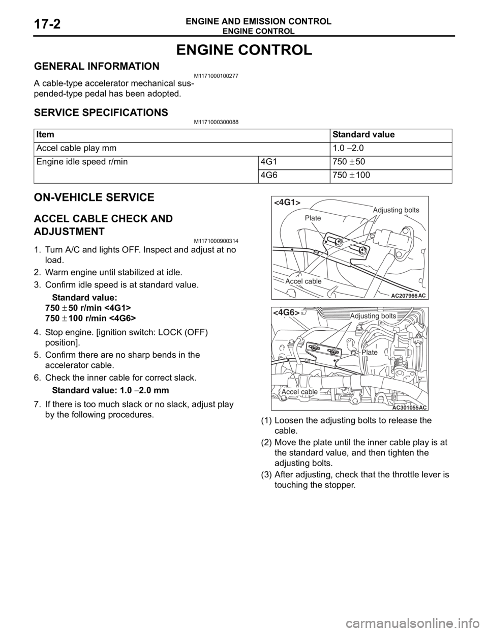
1. Turn A/C and lights OFF. Inspect and adjust at no load.
2. Warm engine until stabilized at idle.
3. Confirm idle speed is at standard value.
Standard value:
750 ± 50 r/min <4G1>
750 ± 100 r/min <4G6>
4. Stop engine. [ignition switch: LOCK (OFF)
position].
5. Confirm there are no sharp bends in the accelerator cable.
6. Check the inner cable for correct slack.
Standard value: 1.0 − 2.0 mm
7. If there is too much slack or no slack, adjust play by the following procedures.
AC207966
Adjusting bolts
Plate
Accel cable
AC
<4G1>
AC301055
Adjusting bolts
Plate
Accel cable
AC
<4G6>
(1) Loosen th e adjusting bo lt s to re lease the
cab l e.
(2) M o v e th e pla t e until the inne r cab l e play is a t
the st andard value, an d then tighte n the
adjusting bo lt s.
(3) A f t e r adju s ting, check that the thro ttle leve r is
touching the stoppe r .
Page 109 of 800
ENGINE CONTROL
ENGINE AND EMISSION CONTROL17-3
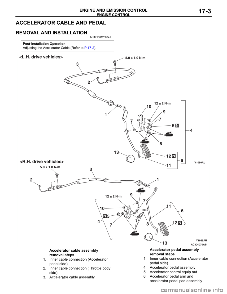
ACCELERATOR CABLE AND PEDAL
REMOVAL AND INSTALLATION
M1171001200341
Post-installation Operation
Adjusting the Accelerator Cable (Refer to P.17-2).
Y1059AU
Y1060AU
AC304070
N
4
5 7 8
10
11
N12
13
AB
1
2 3
5.0 ± 1.0 N·m
6
12 ± 2 N·m9
7
1
2
3
5.0 ± 1.0 N·m
N
4
5
7
8
10
11
N12
13
6
12 ± 2 N·m
9
7
Accelerator cable assembly
removal steps
1.Inner cable connection (Accelerator
pedal side)
2.Inner cable connection (Throttle body
side)
3.Accelerator cable assembly
Accelerator pedal assembly
removal steps
1.Inner cable connection (Accelerator
pedal side)
4.Accelerator pedal assembly
5.Accelerator control equip nut
6.Accelerator pedal arm and
accelerator pedal pad assembly
Page 110 of 800

EMISSION CONTROL
ENGINE AND EMISSION CONTROL17-4
INSTALLATION SERVICE POINT
>>A<< ACCEL PEDAL PAD INSTALLA-
TION
CAUTION
To prevent damages to the accelerator pedal pad,
warm the thumb area of the accelerator pedal
pad with a dryer, etc. prior to assembling it.
NOTE: If it is difficult to assemble, apply soapy water
to the thumb area to enhance the assembling proc
-
ess.
EMISSION CONTROL
GENERAL INFORMATION
M1173000100370
The emission control system consists of the following
subsystems:
•Crankcase emission control system
•Evaporative emission control system
•
ItemsNameSpecification
Crankcase emission control
systemPositive crankcase ventilation
(PCV) valveVariable flow type
(Purpose: HC reduction)
Evaporative emission control
systemCanister
Purge control solenoid valve
Equipped
Duty cycle type solenoid valve
(Purpose: HC reduction)
Exhaust emission control systemAir-fuel ratio control device - MPI
systemOxygen sensor feedback type
(Purpose: CO, HC, NOx reduction)
Exhaust gas recirculation system
•EGR valve
•EGR control solenoid valve
Equipped
Single type
Duty cycle type solenoid valve
(Purpose: NOx reduction)
Catalytic converterMonolith type
(Purpose: CO, HC, NOx reduction)
Exhaust emission control system
EMISSION CONTROL DEVICE
REFERENCE TABLE
M1173006600135
Related partsCrankcase
emission
control
systemEvaporative
emission
control
systemAir/fuel ratio
control
systemCatalytic
converterExhaust gas
recirculation
system
PCV valve×
Purge control solenoid valve×
MPI system component××
Catalytic converter×
EGR valve×
EGR control solenoid valve×
7.Accelerator control equip bushing
8.Accelerator pedal arm return spring
9.Accelerator pedal arm stopper
10.Accelerator pedal arm bracket
11 .Accelerator pedal arm
>>A<<12.Accelerator pedal pad
13.Accelerator pedal arm stopper
Accelerator pedal assembly
removal steps (Continued)