control MITSUBISHI LANCER 2006 Owner's Manual
[x] Cancel search | Manufacturer: MITSUBISHI, Model Year: 2006, Model line: LANCER, Model: MITSUBISHI LANCER 2006Pages: 800, PDF Size: 45.03 MB
Page 39 of 800
AC301429
1
2 36
7
13 ± 2 N·m
AD
5
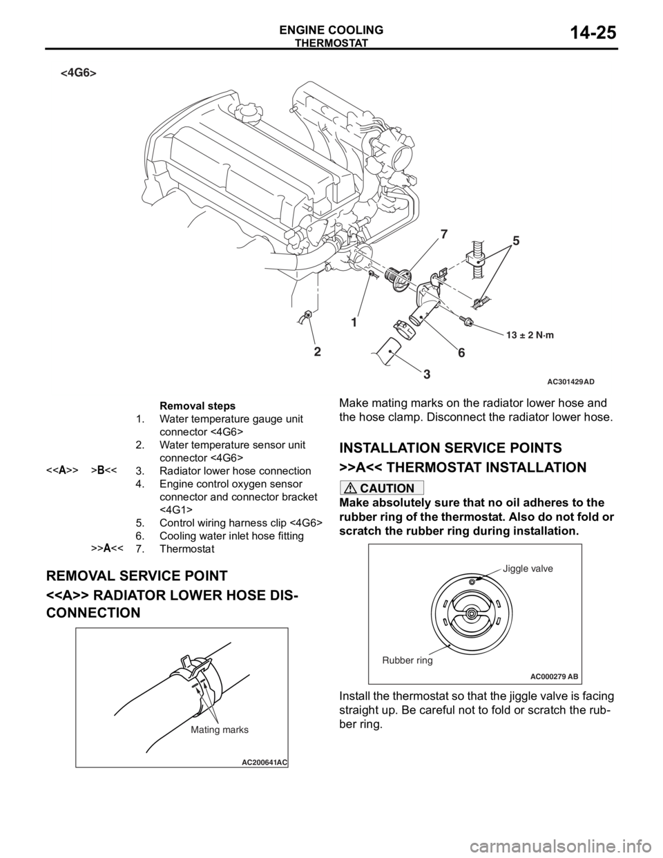
<4G6>
Removal steps
1.Water temperature gauge unit
connector <4G6>
2.Water temperature sensor unit
connector <4G6>
<>>B<<3.Radiator lower hose connection
4.Engine control oxygen sensor
connector and connector bracket
<4G1>
5.Control wiring harness clip <4G6>
6.Cooling water inlet hose fitting
>>A<<7.Thermostat
THERMOST
A T
ENGINE COOLING14-25
REMOV A L SER V ICE POINT
<> RADIAT OR LOW E R HOSE DIS-
CONNECTION
AC200641AC
Mating marks
Make mating marks on the rad i ator lower ho se an d
the hose clamp. Disconn
ect t he radiator lower hose.
INSTALLA T ION SER VICE POINTS
>>A<< THERMOSTA T INST ALLA TION
CAUTION
Make absolutely sure that no oil adheres to the
rubber ring of the thermostat. Also do not fold or
scratch the rubber ring during installation.
AC000279
Jiggle valve
Rubber ring
AB
Install the thermostat so that the jiggle valve is facing
straight up. Be careful not to fold or scratch the rub
-
ber ring.
Page 43 of 800
WATER HOSE AND WATER PIPE
ENGINE COOLING14-29
WATER HOSE AND WATER PIPE
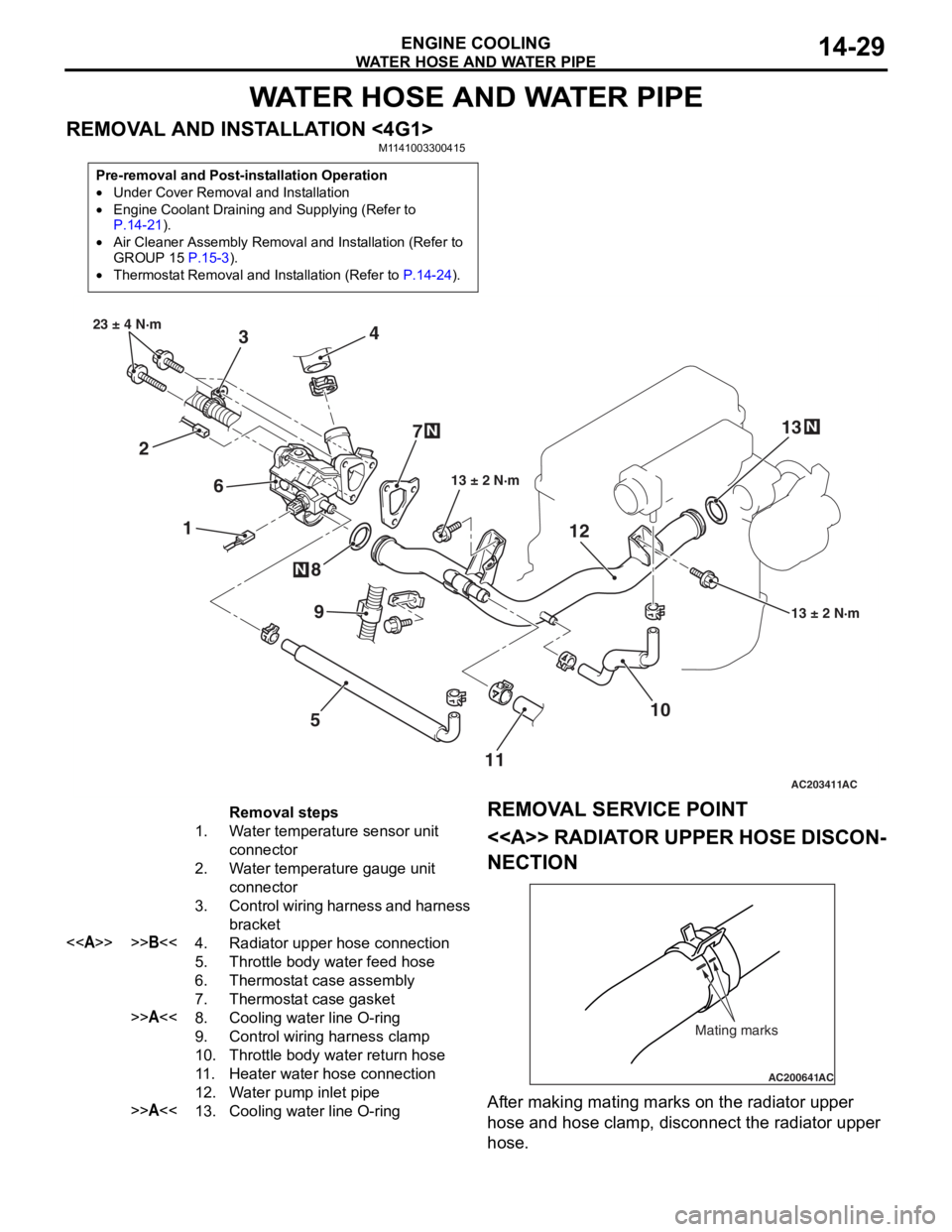
REMOVAL AND INSTALLATION <4G1>M1141003300415
Pre-removal and Post-installation Operation
•Under Cover Removal and Installation
•Engine Coolant Draining and Supplying (Refer to P.14-21).
•Air Cleaner Assembly Removal and Installation (Refer to
GROUP 15 P.15-3).
•Thermostat Removal and Installation (Refer to P.14-24).
AC203411
1
2 3
4
5
6
7
8
10
9
13 ± 2 N·m
23 ± 4 N·m
13 ± 2 N·m
N
N
AC
1112
13
N
Removal steps
1.Water temperature sensor unit
connector
2.Water temperature gauge unit
connector
3.Control wiring harness and harness
bracket
<>>>B<<4.Radiator upper hose connection
5.Throttle body water feed hose
6.Thermostat case assembly
7.Thermostat case gasket
>>A<<8.Cooling water line O-ring
9.Control wiring harness clamp
10.Throttle body water return hose
11 .Heater water hose connection
12.Water pump inlet pipe
>>A<<13.Cooling water line O-ring
REMOV
A L SER VICE POINT
<> RADIAT OR UPPER HOSE DISCON-
NECTION
AC200641AC
Mating marks
After making matin g ma rks on the radia t or upp er
hose
and h o se clamp, disconnect the radia t or upp er
hose
.
Page 45 of 800
WATER HOSE AND WATER PIPE
ENGINE COOLING14-31
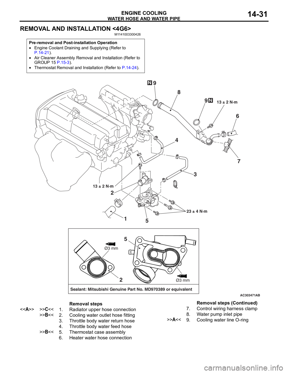
REMOVAL AND INSTALLATION <4G6>
M1141003300426
Pre-removal and Post-installation Operation
•Engine Coolant Draining and Supplying (Refer to P.14-21).
•Air Cleaner Assembly Removal and Installation (Refer to
GROUP 15 P.15-3).
•Thermostat Removal and Installation (Refer to P.14-24).
AC303471
1
2
3
4
5 6
7
8
9
9
13 ± 2 N·m
23 ± 4 N·m
13 ± 2 N·m
N
N
AB
2
Sealant: Mitsubishi Genuine Part No. MD970389 or equivalent
Ø3 mm
Ø3 mm
5
Removal steps
<>>>C<<1.Radiator upper hose connection
>>B<<2.Cooling water outlet hose fitting
3.Throttle body water return hose
4.Throttle body water feed hose
>>B<<5.Thermostat case assembly
6.Heater water hose connection
7.Control wiring harness clamp
8.Water pump inlet pipe
>>A<<9.Cooling water line O-ring
Removal steps (Continued)
Page 48 of 800
AC303473
18
17 15
20
12
9
13
5
2
9
3
4
1
10
6
10
12 ± 2 N·m
AC
12 ± 2 N·m
16
19
8
11
7
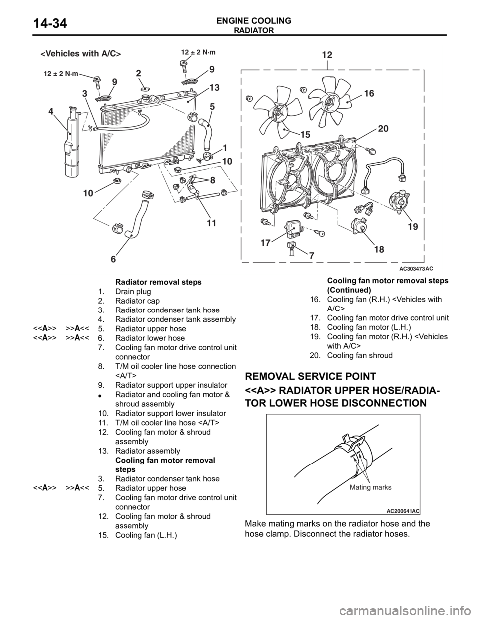
Radiator removal steps
1.Drain plug
2.Radiator cap
3.Radiator condenser tank hose
4.Radiator condenser tank assembly
<>>>A<<5.Radiator upper hose
<>>>A<<6.Radiator lower hose
7.Cooling fan motor drive control unit
connector
8.T/M oil cooler line hose connection
9.Radiator support upper insulator
•Radiator and cooling fan motor &
shroud assembly
10.Radiator support lower insulator
11 .T/M oil cooler line hose
12.Cooling fan motor & shroud
assembly
13.Radiator assembly
Cooling fan motor removal
steps
3.Radiator condenser tank hose
<>>>A<<5.Radiator upper hose
7.Cooling fan motor drive control unit
connector
12.Cooling fan motor & shroud
assembly
15.Cooling fan (L.H.)
16.Cooling fan (R.H.)
17.Cooling fan motor drive control unit
18.Cooling fan motor (L.H.)
19.Cooling fan motor (R.H.)
20.Cooling fan shroud
RADIA T OR
ENGINE COOLING14-34
REMOV A L SER VICE POINT
<> RADIAT OR UPPER HOSE/RADIA-
TO R LOW E R HOSE DISCONNECTION
AC200641AC
Mating marks
Make mating marks on the rad i ator hose and th e
hose
cla m p. Disconnect the ra diat or hoses.
Cooling fan motor removal steps
(Continued)
Page 49 of 800
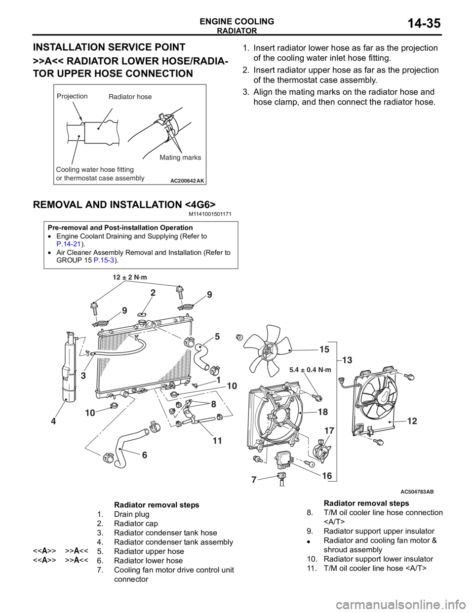
RADIATOR
ENGINE COOLING14-35
INSTALLATION SERVICE POINT
>>A<< RADIATOR LOWER HOSE/RADIA-
TOR UPPER HOSE CONNECTION
AC200642
Mating marks
Projection
Cooling water hose fitting
or thermostat case assembly
AK
Radiator hose
1.In sert ra diato r lower h o se as fa r as th e projection
o f the cooling wate r inlet hose fit t ing.
2.In sert radia t or up per h o se as far a s t he pro j ection
o f the th ermost at ca se asse mbly .
3.Align th e ma ting marks on the rad i ator hose and
h o se clamp, an d then conn ect the radiator h o se.
REMOVA L AND INST ALLA TION <4G6>
M11 4100 1501 17 1
Pre-removal and Post-installation Operation
•Engine Coolant Draining and Supplying (Refer to
P.14-21).
•Air Cleaner Assembly Removal and Installation (Refer to
GROUP 15
P.15-3).
AC504783
1
12 ± 2 N·m
10
2
3
4
5
6
7
8
9
9
10
11 13
15
18
16
17
12
AB
5.4 ± 0.4 N·m
Radiator removal steps
1.Drain plug
2.Radiator cap
3.Radiator condenser tank hose
4.Radiator condenser tank assembly
<>>>A<<5.Radiator upper hose
<>>>A<<6.Radiator lower hose
7.Cooling fan motor drive control unit
connector
8.T/M oil cooler line hose connection
9.Radiator support upper insulator
•Radiator and cooling fan motor &
shroud assembly
10.Radiator support lower insulator
11 .T/M oil cooler line hose
Radiator removal steps
Page 52 of 800
GENERAL INFORMATION
INTAKE AND EXHAUST15-2
GENERAL INFORMATION
M1151000100402
The exhaust pipe is divided into three parts.
SERVICE SPECIFICATION
M1151000300428
ItemStandard valueLimit
Manifold distortion of the installation surface mm0.15 or less0.20
SPECIAL TOOL
M1151000600399
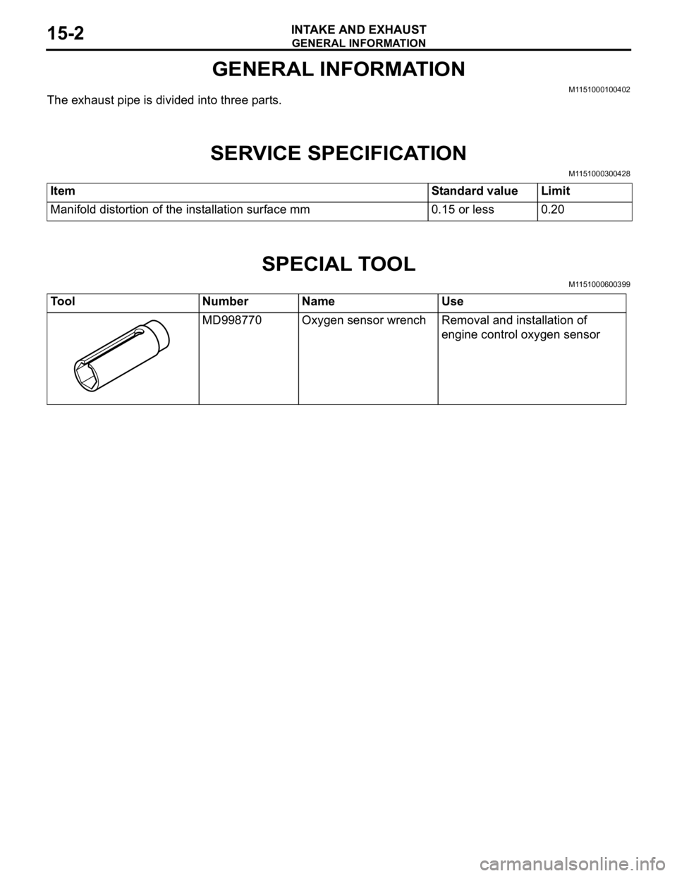
ToolNumberNameUse
MD998770Oxygen sensor wrenchRemoval and installation of
engine control oxygen sensor
Page 55 of 800
INLET MANIFOLD
INTAKE AND EXHAUST15-5
INLET MANIFOLD
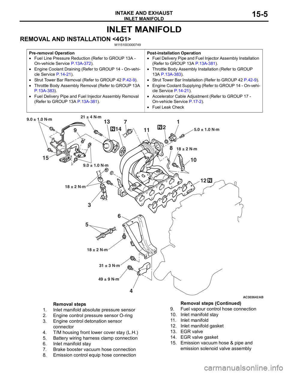
REMOVAL AND INSTALLATION <4G1>M1151003000749
Pre-removal Operation
•Fuel Line Pressure Reduction (Refer to GROUP 13A -
On-vehicle Service
P.13A-372).
•Engine Coolant Draining (Refer to GROUP 14 - On-vehi-
cle Service P.14-21).
•Strut Tower Bar Removal (Refer to GROUP 42 P.42-9).
•Throttle Body Assembly Re moval (Refer to GROUP 13A
P.13A-383).
•Fuel Delivery Pipe and Fuel Injector Assembly Removal
(Refer to GROUP 13A
P.13A-381).
Post-installation Operation
•Fuel Delivery Pipe and Fuel Injector Assembly Installation
(Refer to GROUP 13A
P.13A-381).
•Throttle Body Assembly Inst allation (Refer to GROUP
13A
P.13A-383).
•Strut Tower Bar Installati on (Refer to GROUP 42 P.42-9).
•Engine Coolant Supplying (Refer to GROUP 14 - On-vehi-
cle Service P.14-21).
•Accelerator Cable Adjustment (Refer to GROUP 17 -
On-vehicle Service
P.17-2).
•Fuel Leak Check
AC303642AB
15
36
5
4 12
10
7
1
2
11
9 13
14
21 ± 4 N·m
9.0 ± 1.0 N·m
9.0 ± 1.0 N·m
18 ± 2 N·m
18 ± 2 N·m 18 ± 2 N·m
5.0 ± 1.0 N·m
31 ± 3 N·m
49 ± 9 N·m
N
N
N
8
Removal steps
1.Inlet manifold absolute pressure sensor
2.Engine control pressure sensor O-ring
3.Engine control detonation sensor
connector
4.T/M housing front lower cover stay (L.H.)
5.Battery wiring harness clamp connection
6.Inlet manifold stay
7.Brake booster vacuum hose connection
8.Emission control equip hose connection
9.Fuel vapour control hose connection
10.Inlet manifold stay
11 .Inlet manifold
12.Inlet manifold gasket
13.EGR valve
14.EGR valve gasket
15.Emission vacuum hose & pipe and
emission solenoid valve assembly
Removal steps (Continued)
Page 56 of 800
INLET MANIFOLD
INTAKE AND EXHAUST15-6
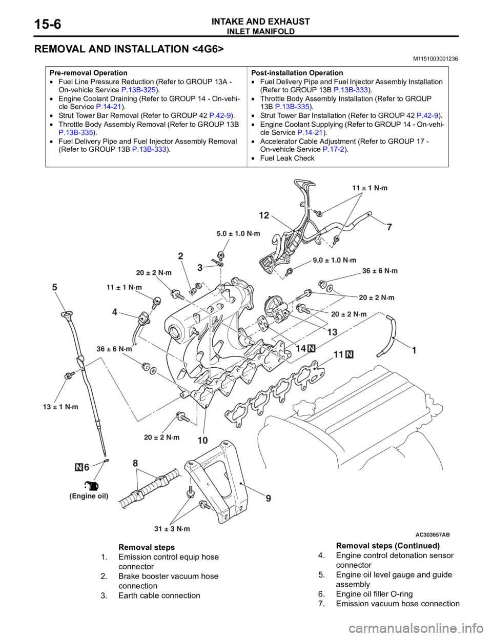
REMOVAL AND INSTALLATION <4G6>
M1151003001236
Pre-removal Operation
•Fuel Line Pressure Reduction (Refer to GROUP 13A -
On-vehicle Service P.13B-325).
•Engine Coolant Draining (Refer to GROUP 14 - On-vehi-cle Service P.14-21).
•Strut Tower Bar Removal (Refer to GROUP 42 P.42-9).
•Throttle Body Assembly Re moval (Refer to GROUP 13B
P.13B-335).
•Fuel Delivery Pipe and Fuel Injector Assembly Removal
(Refer to GROUP 13B
P.13B-333).
Post-installation Operation
•Fuel Delivery Pipe and Fuel Injector Assembly Installation
(Refer to GROUP 13B P.13B-333).
•Throttle Body Assembly Inst allation (Refer to GROUP
13B P.13B-335).
•Strut Tower Bar Installati on (Refer to GROUP 42 P.42-9).
•Engine Coolant Supplying (Refer to GROUP 14 - On-vehi-
cle Service P.14-21).
•Accelerator Cable Adjustment (Refer to GROUP 17 -
On-vehicle Service
P.17-2).
•Fuel Leak Check
AC303657
9.0 ± 1.0 N·m11 ± 1 N·m
20 ± 2 N·m 31 ± 3 N·m
36 ± 6 N·m
20 ± 2 N·m
20 ± 2 N·m
36 ± 6 N·m
20 ± 2 N·m
11
9
10
2
12
N14
13N
AB
5.0 ± 1.0 N·m
3
1
11 ± 1 N·m
4
N
13 ± 1 N·m
5
6
(Engine oil)
7
8
Removal steps
1.Emission control equip hose
connector
2.Brake booster vacuum hose
connection
3.Earth cable connection
4.Engine control detonation sensor
connector
5.Engine oil level gauge and guide
assembly
6.Engine oil filler O-ring
7.Emission vacuum hose connection
Removal steps (Continued)
Page 58 of 800
Removal steps
1.Front exhaust pipe connection
2.Exhaust pipe gasket
<>>>A<<3.Engine control oxygen sensor (front)
4.Engine oil level gauge and guide
assembly
5.Engine oil filler O-ring
6.Exhaust manifold cover
7.Exhaust manifold bracket
8.Exhaust manifold
9.Exhaust manifold gasket
EXHAUST MANIFOLD
INTAKE AND EXHAUST15-8
REMOVAL SERVICE POINT
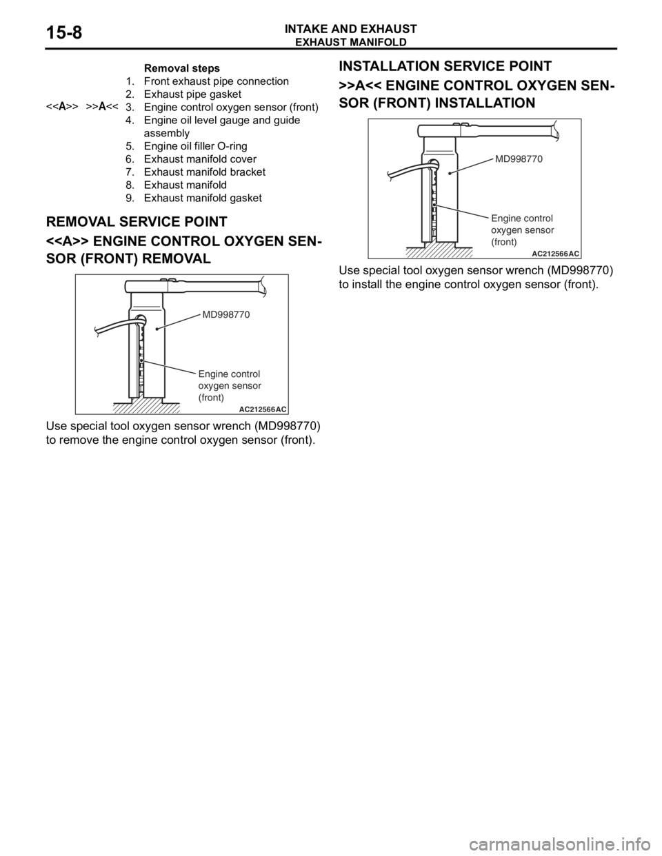
<> ENGINE CONTROL OXYGEN SEN-
SOR (FRONT) REMOVAL
AC212566AC
MD998770
Engine control
oxygen sensor
(front)
Use spe c ia l tool oxyg en sen s or wrench (MD9987 70)
to remove t
he eng ine contro l oxygen sen s or (fro nt).
INSTALLA T ION SER VICE POINT
>>A<< ENGINE CONT ROL OXYGEN SEN-
SOR (FRONT) INSTALLA TION
AC212566AC
MD998770
Engine control
oxygen sensor
(front)
Use spe c ia l tool oxyg en sen s or wrench (MD9987 70)
to inst
all the eng ine contro l oxyge n sen s or (f ront).
Page 59 of 800
EXHAUST MANIFOLD
INTAKE AND EXHAUST15-9
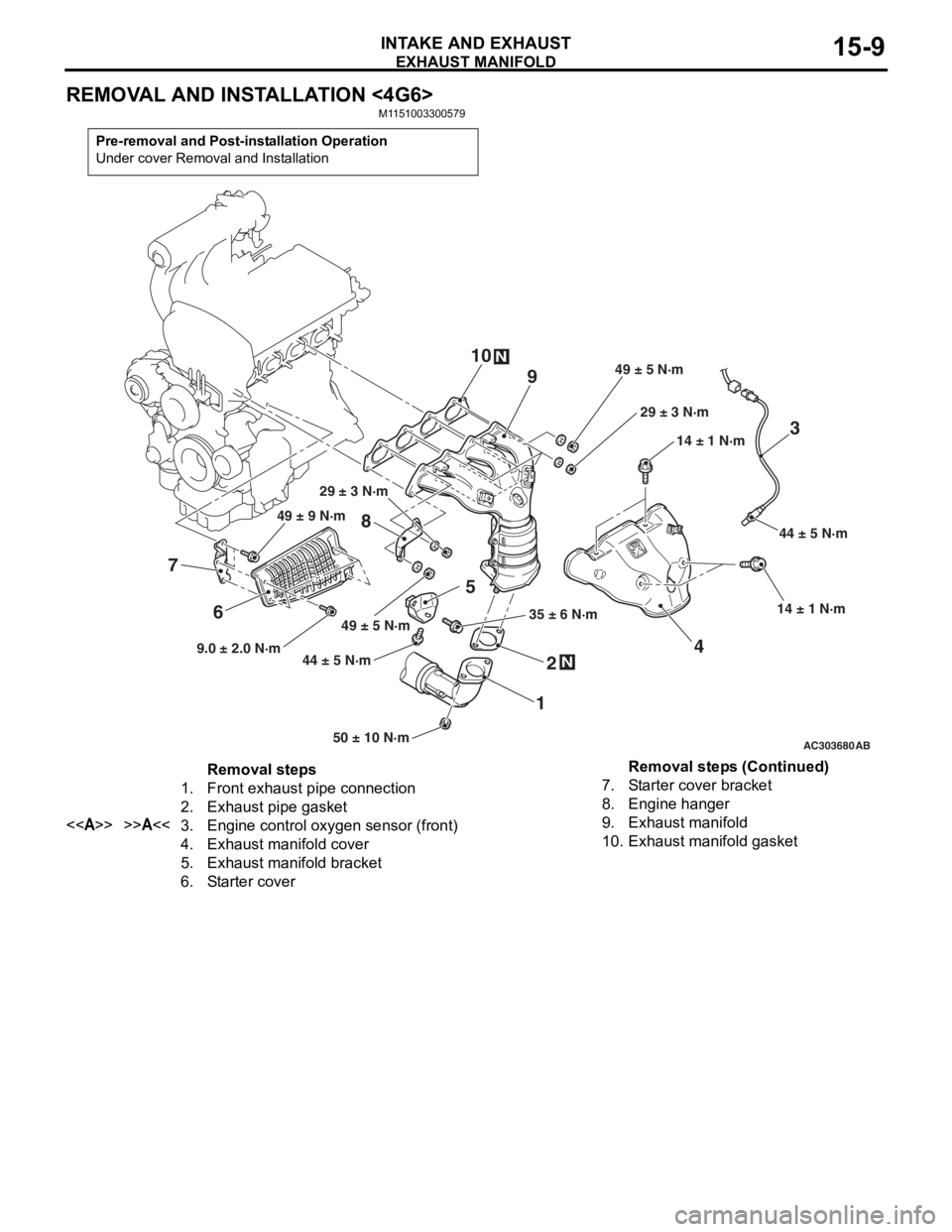
REMOVAL AND INSTALLATION <4G6>
M1151003300579
Pre-removal and Post-installation Operation
Under cover Removal and Installation
AC30368050 ± 10 N·m
44 ± 5 N·m
35 ± 6 N·m14 ± 1 N·m
14 ± 1 N·m
49 ± 5 N·m 29 ± 3 N·m
29 ± 3 N·m
N
3
4
1 2
5
N
8 944 ± 5 N·m
AB
1049 ± 5 N·m
6
7
9.0 ± 2.0 N·m 49 ± 9 N·m
Removal steps
1.Front exhaust pipe connection
2.Exhaust pipe gasket
<>>>A<<3.Engine control oxygen sensor (front)
4.Exhaust manifold cover
5.Exhaust manifold bracket
6.Starter cover
7.Starter cover bracket
8.Engine hanger
9.Exhaust manifold
10.Exhaust manifold gasket
Removal steps (Continued)