control MITSUBISHI LANCER 2006 Repair Manual
[x] Cancel search | Manufacturer: MITSUBISHI, Model Year: 2006, Model line: LANCER, Model: MITSUBISHI LANCER 2006Pages: 800, PDF Size: 45.03 MB
Page 121 of 800
EMISSION CONTROL
ENGINE AND EMISSION CONTROL17-15
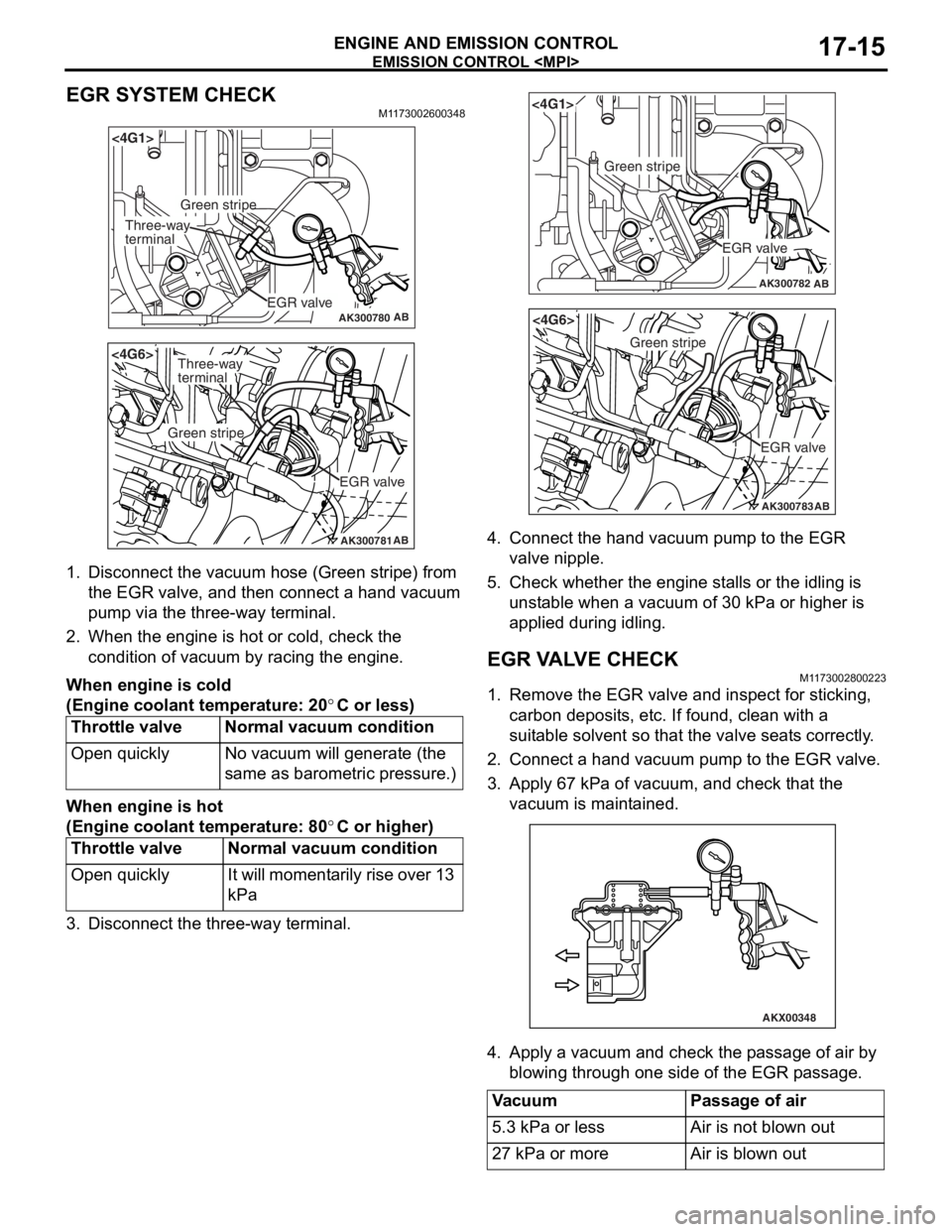
EGR SYSTEM CHECK
M1173002600348
AK300780AB
<4G1>
EGR valve
Green stripe
Three-way
terminal
AK300781AB
<4G6>
EGR valve
Green stripe
Three-way
terminal
1.Disco nnect the vacu um ho se (Green stripe) from
th e EGR valve, a nd th en connect a hand vacuum
pu mp via t he thre e-way te rmin al.
2.Wh en the engine is hot o r cold, check the
condition of va cuum by racing the engine.
When engine is c o ld
(Eng ine coo lant tem perature: 20°C or less)
Throttle valveNormal vacuum co ndition
Open quicklyNo va cuum will gene rate (th e
same as baro
m etric pre s sure.)
When engine is h o t
(Eng ine coo lant tem perature: 80°C or higher)
Throttle valveNormal vacuum c ondition
Open quicklyIt will mo me nt a r i l y rise o v er 13
kPa
3.Disco nnect the th ree-way t e rminal.
AK300782AB
<4G1>
EGR valve
Green stripe
AK300783AB
<4G6>
EGR valve
Green stripe
4.Conn ect the han d va cuum pump to t he EGR
valve nipple.
5.Check whe t her th e engine st alls or the idling is
u n st able when a vacuum of 30 kPa or h i gher is
a pplied during idling.
EGR V A L V E CHECKM1173 0028 0022 3
1.Remove the EGR valve an d inspect for stickin g ,
carbon deposit s, e t c. If found , clean with a
suit able so lve n t so that th e va lve seat s corre ctly .
2.Conn ect a hand vacuum pump to the EGR va lve .
3.App l y 6 7 kPa of va cuum, and check t hat the
vacu um is maint a ined.
AKX00348
4.App l y a vacuum and chec k th e p a ssage of air by
b l owing throug h one side of the EGR p a ssage.
VacuumPassage of air
5.3 kPa or lessAir is not blown out
27 kPa or moreAir is blown out
Page 122 of 800
EMISSION CONTROL
ENGINE AND EMISSION CONTROL17-16
5. Replace the gasket, and tighten to the specified torque.
Tightening torque:
<4G1> 21 ± 4 N⋅m
<4G6> 20 ± 2 N⋅m
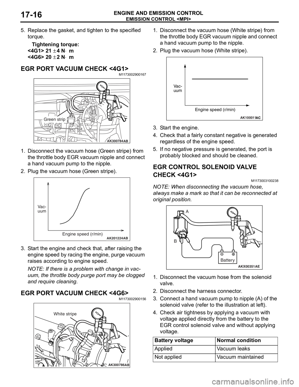
EGR PORT VACUUM CHECK <4G1>M1173002900167
AK300784AB
Green strip
1.Disco nnect the vacu um ho se (Green stripe) from
th e t h ro tt le b o d y EGR va cuu m ni pp le an d co nn ec t
a hand vacu um p u mp to the nipple.
2.Plu g the vacuum hose (Gree n stripe).
AK201224AB
Vac-
uum
Engine speed (r/min)
3.S t art the engin e and check t hat, af ter ra ising th e
engine spe ed by ra cin g the e ngine, p u rge vacuu m
raises according to engine speed.
NOTE: If ther e is a prob lem with change in vac-
uum, the t h rottle bod y p u rge port may be clo gged
an
d requ ire clean ing.
EGR PORT VA CUUM CHECK <4G6>M1173 0029 0015 6
AK300786AB
White stripe
1.Disco nnect the vacu um h o se (W hite strip e ) from
th e t h ro tt le b o d y EGR va cuu m ni pp le an d co nn ec t
a hand vacuum p u mp to the nipple.
2.Plug the vacuum hose (White stripe).
AK100011AC
Vac-
uum
Engine speed (r/min)
3.S t art the engine.
4.Check that a fairly const a nt n egative is gene rated
re gardle s s of the engine sp eed.
5.If no neg ative pressur e is genera t ed, th e port is
p r obably blocked an d sh ould be cleane d.
EGR CONTROL SOLENOID VA L V E
CHECK <
4 G1 >
M1173 0031 0023 8
NOTE: Whe n discon nect i ng th e va cuum hose,
always make a mark so th at it can be reconnected at
original p o sition.
AKX00351
A
B
AE
Battery
1. Disco nnect the vacu um h o se f r om th e solenoid
valve.
2.Disco nnect the ha rness connector .
3.Con nect a ha nd vacu um pump to nipp le (A) of the
solen o id valve (ref e r to th e ill ust r ation at le f t ).
4.Check a i r tightness b y ap plying a vacuum with
volt age applied d i rectly from t he batt e ry to the
EGR cont rol solen o id valve and withou t applyin g
volt age .
Battery voltageNormal condition
AppliedVa c u u m l e a k s
Not appliedVacuum maintained
Page 123 of 800
AKX00352
EMISSI ON CONTROL
ENGINE AND E M ISSION CON T R O L17-17
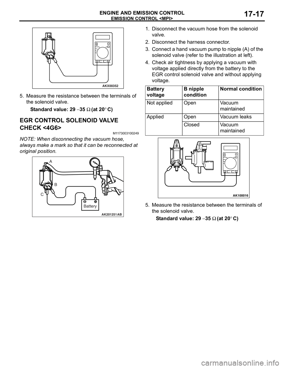
5.Measure the resist ance between the te rmin als of
th e solenoid va lve .
St andard va lue: 29 − 35 Ω (at 20°C)
EGR CONTROL SOLENOID V A L V E
CHECK <
4 G6>
M1173 0031 0024 9
NOTE: Whe n discon nect i ng th e va cuum hose,
always
make a mark so th at it can be reconnected at
original p o sition.
AK201251AB
A
B
C
Battery
1.Disco nnect the vacu um h o se f r om th e solenoid
valve.
2.Disco nnect the ha rness connector .
3.Con nect a ha nd vacu um pump to nipp le (A) of the
solen o id valve (ref e r to th e ill ust r ation at le f t ).
4.Check a i r tightness b y ap plying a vacuum with
volt age applied d i rectly from t he batt e ry to the
EGR cont rol solen o id valve and withou t applyin g
volt age .
Battery
voltageB nipple
conditionNormal condition
Not appliedOpenVacuum
maintained
AppliedOpenVacuum leaks
ClosedVacuum
maintained
AK100016
5.Measure the resist ance betwee n the te rminals of
th e so lenoid valve .
St andard va lue: 29 − 35 Ω (at 20°C)
Page 124 of 800
EMISSION CONTROL
ENGINE AND EMISSION CONTROL17-18
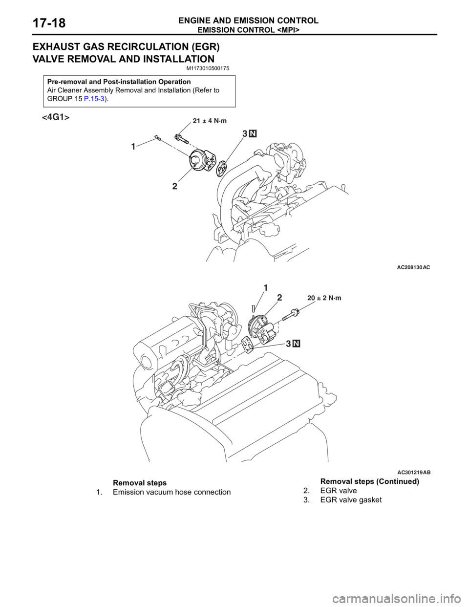
EXHAUST GAS RECIRCULATION (EGR)
VALVE REMOVAL AND INSTALLATION
M1173010500175
Pre-removal and Post-installation Operation
Air Cleaner Assembly Removal and Installation (Refer to
GROUP 15
P.15-3).
AC208130
21 ± 4 N·m
2
1
3
N
AC
<4G1>
AC301219
20 ± 2 N·m2
1
3
N
AB
Removal steps
1.Emission vacuum hose connection2.EGR valve
3.EGR valve gasket
Removal steps (Continued)
Page 125 of 800
EMISSION CONTROL
ENGINE AND EMISSION CONTROL17-19
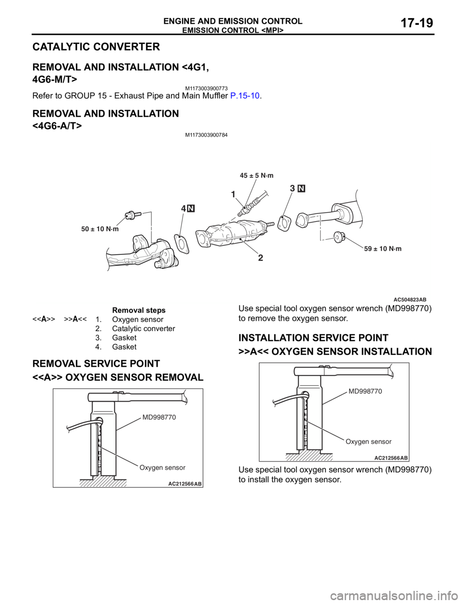
CATALYTIC CONVERTER
REMOVAL AND INSTALLATION <4G1,
4G6-M/T>
M1173003900773
Refer to GROUP 15 - Exhaust Pipe and Main Muffler P.15-10.
REMOVAL AND INSTALLATION
<4G6-A/T>
M1173003900784
AC504823
2
3N
N4
59 ± 10 N·m
50 ± 10 N·m
1
45 ± 5 N·m
AB
Removal steps
<>>>A<<1.Oxygen sensor
2.Catalytic converter
3.Gasket
4.Gasket
REMOVA L SER V ICE POINT
<> OXYGEN SENSOR REMOV A L
AC212566AB
MD998770
Oxygen sensor
Use spec ia l tool oxyg en sen s or wrench (MD9987 70)
to remove
the oxyge n sen s or .
INSTALLA T ION SER VICE POINT
>>A<< OXYGEN SENSOR INST ALL A TION
AC212566AB
MD998770
Oxygen sensor
Use spec ia l tool oxyg en sen s or wrench (MD9987 70)
to inst
all the oxyge n sen s or .
Page 183 of 800
33-1
GROUP 33
FRONT
SUSPENSION
CONTENTS
GENERAL INFORMATIO N . . . . . . . .33-2
SERVICE SPECIFICATIONS . . . . . . .33-3
LUBRICANT . . . . . . . . . . . . . . . . . . . .33-3
SPECIAL TOOLS . . . . . . . . . . . . . . . .33-4
ON-VEHICLE SERVICE . . . . . . . . . . .33-6
FRONT WHEEL ALIGNMENT CHECK AND
ADJUSTMENT . . . . . . . . . . . . . . . . . . . . . . 33-6
LOWER ARM BALL JOINT AXIAL PLAY
CHECK . . . . . . . . . . . . . . . . . . . . . . . . . . . . 33-7
LOWER ARM BALL JOINT COVER
CHECK . . . . . . . . . . . . . . . . . . . . . . . . . . . . 33-7
STRUT ASSEMBLY . . . . . . . . . . . . . .33-7
REMOVAL AND INSTALLATION . . . . . . . . 33-7
INSPECTION. . . . . . . . . . . . . . . . . . . . . . . . 33-7
DISASSEMBLY AND REASSEMBLY . . . . . 33-8
INSPECTION. . . . . . . . . . . . . . . . . . . . . . . . 33-10
LOWER ARM . . . . . . . . . . . . . . . . . . .33-11
REMOVAL AND INSTALLATION . . . . . . . . 33-11
INSPECTION. . . . . . . . . . . . . . . . . . . . . . . . 33-12
LOWER ARM BALL JOINT COVER
REPLACEMENT . . . . . . . . . . . . . . . . . . . . . 33-12
LOWER ARM BUSHING (REAR)
REPLACEMENT . . . . . . . . . . . . . . . . . . . . . 33-13
STABILIZER BAR. . . . . . . . . . . . . . . .33-14
REMOVAL AND INSTALLATION . . . . . . . . 33-14
INSPECTION. . . . . . . . . . . . . . . . . . . . . . . . 33-16
WARNINGS REGARDING SERVICING OF SUPPLEMENTAL RESTRAINT SYSTEM (SRS) EQUIPPED VEHICLES
WARNING
•Improper service or maintenance of any component of the SRS, or any SRS-related component, can lead to
personal injury or death to service personnel (from inad vertent firing of the air bag) or to the driver and
paassenger (from rendering the SRS inoperative).
•Service or maintenance of any SRS component or SRS-related component must be performed only at an
authorized MITSUBISHI dealer.
•MITSUBISHI dealer personnel must thoroughly review this manual, and especially its GROUP 52B - Supplemental
Restraint System (SRS) before beginning any service or maintenance of any component of the SRS or any
SRS-related component.
NOTE
The SRS includes the following components: SRS air bag control unit, SRS warning light, front impact sensors, air bag module,
clock spring, and interconnecting wiring. Other SRS-related components (that may have to be removed/installed in connection
with SRS service or maintenance) are indicated in the table of contents by an asterisk (*).
Page 199 of 800
34-1
GROUP 34
REAR SUSPENSION
CONTENTS
GENERAL INFORMATION . . . . . . . .34-2
SERVICE SPECIFICATIONS . . . . . . .34-3
LUBRICANT . . . . . . . . . . . . . . . . . . . .34-3
SPECIAL TOOLS . . . . . . . . . . . . . . . .34-4
ON-VEHICLE SERVICE . . . . . . . . . . .34-6
REAR WHEEL ALIGNMENT CHECK AND
ADJUSTMENT . . . . . . . . . . . . . . . . . . . . . . 34-6
CONTROL LINK PILLOW BALL BUSHING
AXIAL PLAY CHECK
UPPER ARM PILLOW BALL BUSHING
AXIAL PLAY CHECK
LOWER ARM PILLOW BALL BUSHING
AXIAL PLAY CHECK . . . . . . . . . . . . . . . . . 34-7
STABILIZER LINK BALL JOINT DUST
COVER INSPECTION . . . . . . . . . . . . . . . . 34-7
CONTROL LINK, UPPER ARM AND
LOWER ARM . . . . . . . . . . . . . . . . . . .34-8
REMOVAL AND INSTALLATION . . . . . . . . 34-8
INSPECTION. . . . . . . . . . . . . . . . . . . . . . . . 34-9
LOWER ARM BUSHING AND LOWER
ARM PILLOW BALL BUSHING
REPLACEMENT . . . . . . . . . . . . . . . . . . . . . 34-10
TRAILING ARM ASSEMBLY . . . . . . .34-12
REMOVAL AND INSTALLATION . . . . . . . . 34-12
INSPECTION. . . . . . . . . . . . . . . . . . . . . . . . 34-13
TRAILING ARM BUSHING
REPLACEMENT . . . . . . . . . . . . . . . . . . . . . 34-13
SHOCK ABSORBER ASSEMBLY . . .34-14
REMOVAL AND INSTALLATION . . . . . . . . 34-14
INSPECTION. . . . . . . . . . . . . . . . . . . . . . . . 34-15
DISASSEMBLY AND REASSEMBLY . . . . . 34-16
STABILIZER BAR. . . . . . . . . . . . . . . .34-19
REMOVAL AND INSTALLATION . . . . . . . . 34-19
INSPECTION. . . . . . . . . . . . . . . . . . . . . . . . 34-19
STABILIZER LINK BALL JOINT DUST
COVER REPLACEMENT . . . . . . . . . . . . . . 34-20
Page 200 of 800
GENERAL INFORMATION
REAR SUSPENSION34-2
GENERAL INFORMATION
M1341000100717
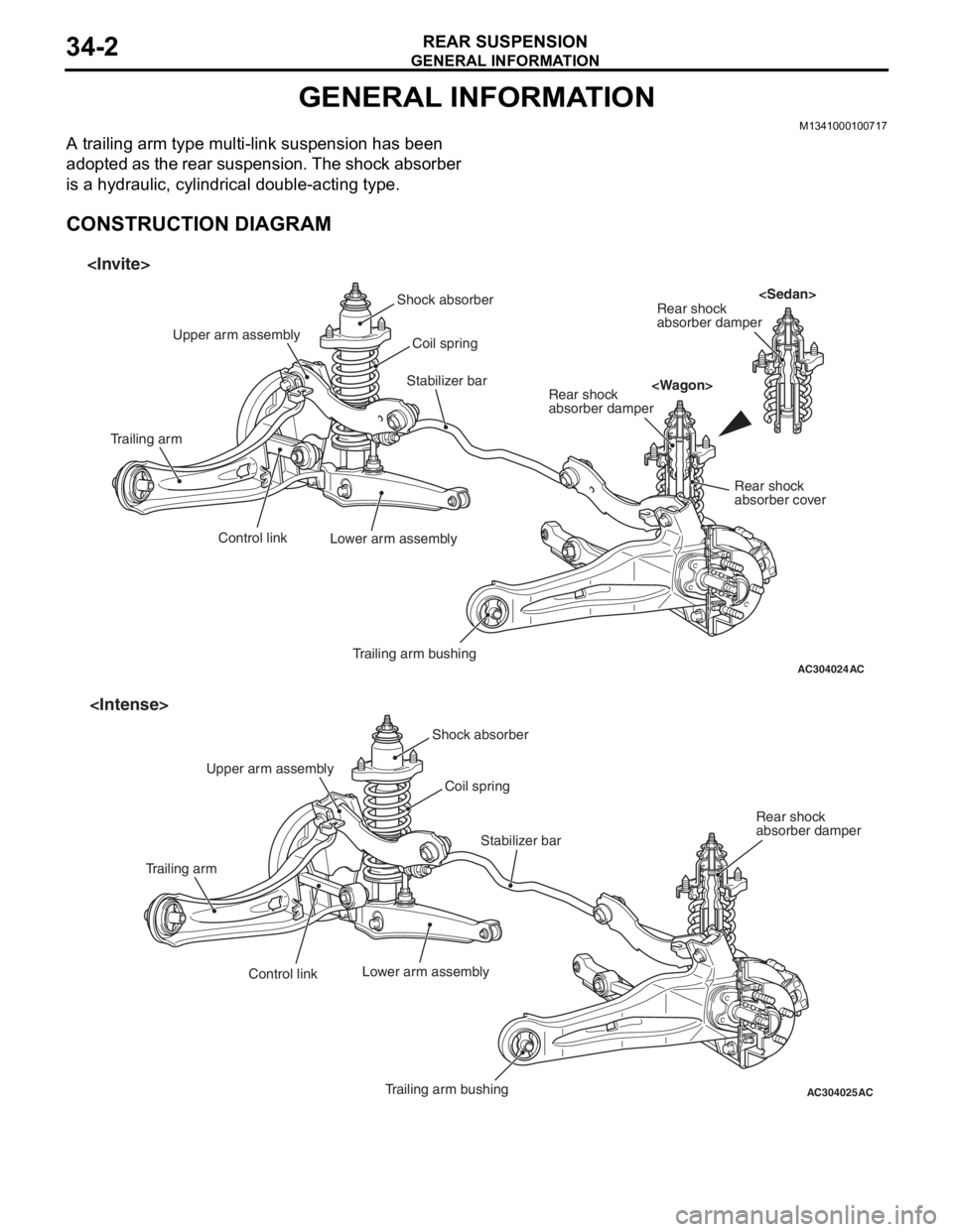
A trailing arm type multi-link suspension has been
adopted as the rear suspension. The shock absorber
is a hydraulic, cylindrical double-acting type.
CONSTRUCTION DIAGRAM
AC304024AC
Shock absorberCoil spring
Trailing arm bushing
Lower arm assembly
Control link
Trailing arm Upper arm assembly
Stabilizer barRear shock
absorber damper
Rear shock
absorber damper Rear shock
absorber cover
AC304025AC
Shock absorber
Trailing arm bushing
Control link
Trailing arm
Stabilizer bar
Coil spring
Lower arm assembly
Rear shock
absorber damper
Upper arm assembly
Page 201 of 800

SERVICE SPECIFICATIONS
REAR SUSPENSION34-3
SPECIFICATION
COIL SPRING
ItemSedanWagon
InviteIntenseInviteIntense
Wire diameter mm10101010
Average diameter mm78 − 9078 − 9078 − 9078 − 90
Free length mm359331377368
SERVICE SPECIFICATIONS
M1341000300733
ItemStandard value
Camber (Difference between right and left within 30') −0°40' ± 0°30'
Toe-inAt the centre of tyre tread mm3 ± 2
Toe-angle (per wheel)0°08' ± 0°05'
Thrust angle0°00' ± 0°09'
Control link pillow ball bushing starting torque
Upper arm pillow ball bushing starting torque
Lower arm pillow ball bushing starting torque N⋅m0.5 − 3.0
Protruding length of stabilizer link bolt mm6 − 8
Stabilizer link ball joint continuous turning torque N⋅m0.5 − 1.5
LUBRICANT
M1341000400172
ItemSpecified lubricantQuantity
Stabilizer link ball joint (inside of dust cover)Multipurpose grease SAE J310, NLGI No.2
or equivalentAs required
Page 204 of 800
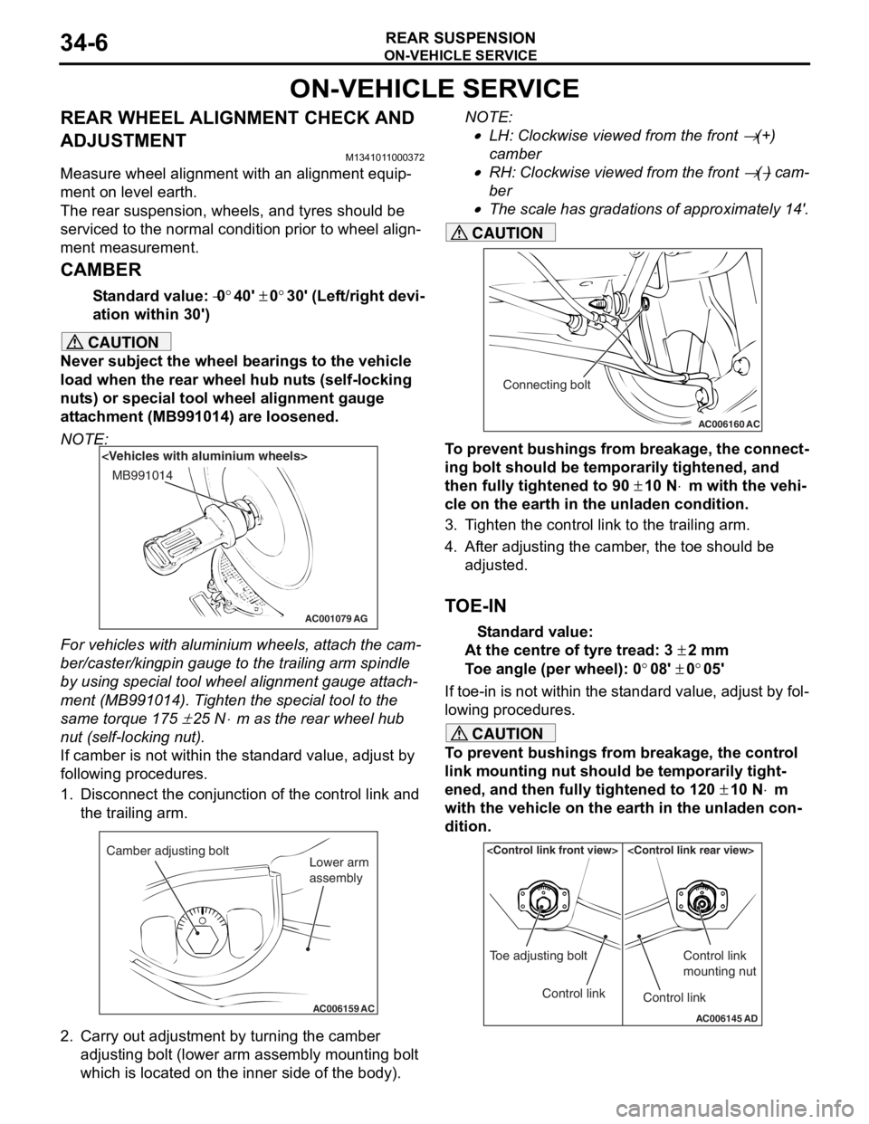
ON-VEHICLE SERVICE
REAR SUSPENSION34-6
ON-VEHICLE SERVICE
REAR WHEEL ALIGNMENT CHECK AND
ADJUSTMENT
M1341011000372
Measure wheel alignment with an alignment equip-
ment on level earth.
The rear suspension, wheels, and tyres should be
serviced to the normal condition prior to wheel align
-
ment measurement.
CAMBER
Standard value: −0°40' ± 0°30' (Left/right devi-
ation within 30')
CAUTION
Never subject the wheel bearings to the vehicle
load when the rear wheel hub nuts (self-locking
nuts) or special tool wheel alignment gauge
attachment (MB991014) are loosened.
NOTE:
AC001079
MB991014
AG
For vehicles with aluminium wheels, attach the cam-
ber/caster/kingpin gauge to the trailing arm spindle
by using special tool wheel alignment gauge attach
-
ment (MB991014). Tighten the special tool to the
same torque 175
± 25 N⋅m as the rear wheel hub
nut (self-locking nut).
If camber is not within the standard value, adjust by
following procedures.
1. Disconnect the conjunction of the control link and the trailing arm.
AC006159 AC
Camber adjusting bolt
Lower arm
assembly
2. Carry out adjustment by turning the camber
adjusting bolt (lower arm assembly mounting bolt
which is located on the inner side of the body).
NOTE: .
•LH: Clockwise viewed from the front → (+)
camber
•RH: Clockwise viewed from the front → (−) cam-
ber
•
AC006160 AC
Connecting bolt
The scale has gradations of approximately 14'.
CAUTION
To prevent bushings from breakage, the connect-
ing bolt should be temporarily tightened, and
then fully tightened to 90
± 10 N⋅m with the vehi-
cle on the earth in the unladen condition.
3. Tighten the control link to the trailing arm.
4. After adjusting the camber, the toe should be
adjusted.
TOE-IN
Standard value:
At the centre of tyre tread: 3 ± 2 mm
Toe angle (per wheel): 0°08' ± 0°05'
If toe-in is not within the standard value, adjust by fol-
lowing procedures.
CAUTION
To prevent bushings from breakage, the control
link mounting nut should be temporarily tight
-
ened, and then fully tightened to 120 ± 10 N⋅m
with the vehicle on the earth in the unladen con
-
dition.
AC006145 AD
Control link
Toe adjusting boltControl link
Control link
mounting nut