fuel MITSUBISHI LANCER 2006 User Guide
[x] Cancel search | Manufacturer: MITSUBISHI, Model Year: 2006, Model line: LANCER, Model: MITSUBISHI LANCER 2006Pages: 800, PDF Size: 45.03 MB
Page 115 of 800
EMISSION CONTROL
ENGINE AND EMISSION CONTROL17-9
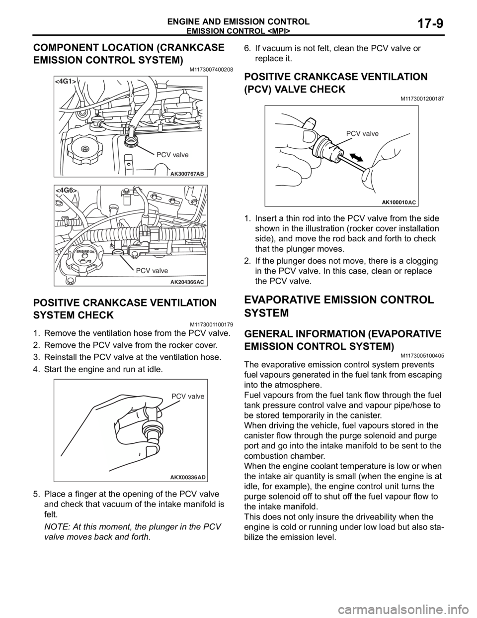
COMPONENT LOCATION (CRANKCASE
EMISSION CONTROL SYSTEM)
M1173007400208
AK300767
<4G1>
AB
PCV valve
AK204366
<4G6>
AC
PCV valve
POSITIVE CRANKCASE VENTILATION
SYSTEM CHECK
M11 7300 1 1 0017 9
1.Remove the ventilatio n hose from the PCV valve.
2.Remove the PCV valve from t he rocker cove r .
3.Reinst all the PCV valve at the ven t ila tion h o se.
4.S t art the engin e and run at idle .
AKX00336
PCV valve
AD
5.Pla c e a fing er at the open ing o f the PCV va lve
an d ch eck that vacu um o f the int a ke manifold is
fe lt.
NOTE: At this mo men t, the p l unge r in t he PCV
valve mo ves back an d forth.
6.If vacuum is not felt, clean t he PCV valve o r
re place it.
POSITIVE CRANKCASE VENTILA TION
(
P CV) V A L VE CHECK
M1173 0012 0018 7
AK100010
PCV valve
AC
1.In sert a thin rod in to the PCV valve from the side
shown in the illu strat i on (ro cke r cover in st allation
side) , and move the ro d back an d forth to ch eck
th at the plung er mo ves.
2.If the plunger does not move , there is a clo ggin g
in the PCV valve. In th is case, clean o r repla c e
th e PCV valve.
EVAPORA T IVE EMISSION CONTROL
SYSTEM
GENERAL INFORMA T ION (EV A PORA TIVE
EMISSION CONTROL SYSTEM)
M1173 0051 0040 5
The evaporat ive emission contro l syste m pre v ent s
f
uel vapours generat ed in t he fuel t ank from escaping
into t
he atmosp here.
Fuel vapours fro m the fuel t a n k flow throug h the f uel
t
a n k pre ssu re co ntrol valve an d vap our pipe/ho se to
be st
ored te mpora r ily in t he ca nister .
When dr iving the veh i cle, fue l va pours stor ed in the
canister
flow thro ugh th e purge solenoid and purge
port an
d go into the int a ke ma nifold to b e sen t to th e
combust
i on chamber .
When the eng ine co ola n t te mp eratu r e is low o r when
the int
a ke air q uantity is small (wh en the engine is at
idle
, for example), t he eng ine contro l unit turns the
purge sole
noid of f to shu t of f the fue l va pour flow to
the in
t a ke manif o ld.
This does not on ly insure the driveability when t he
engin
e is cold or runn ing und er low load b u t also st a
-
bilize the emissio n level.
Page 116 of 800
EMISSION CONTROL
ENGINE AND EMISSION CONTROL17-10
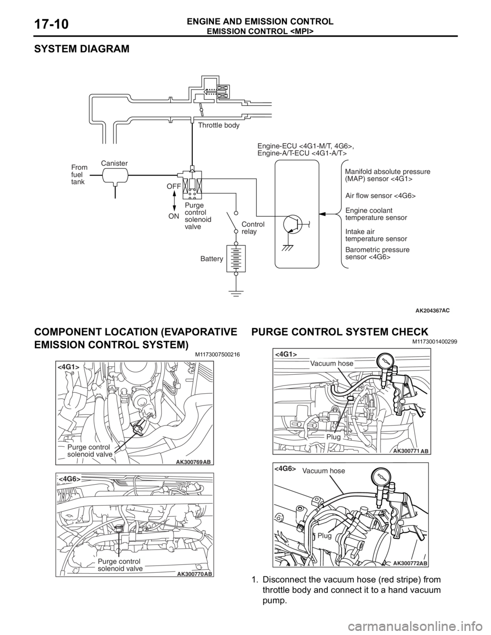
SYSTEM DIAGRAM
AK204367AC
Throttle body
Canister
From
fuel
tank
OFF
ON Purge
control
solenoid
valve
Control
relay
Battery Engine-ECU <4G1-M/T, 4G6>,
Engine-A/T-ECU <4G1-A/T>
Air flow sensor <4G6>Engine coolant
temperature sensor
Intake air
temperature sensor
Barometric pressure
sensor <4G6>
Manifold absolute pressure
(MAP) sensor <4G1>
COMPONENT LOCA
TION (EV A PORA TIVE
EMISSION CONTROL SYSTEM)
M1173 0075 0021 6
AK300769
<4G1>
AB
Purge control
solenoid valve
AK300770
<4G6>
AB
Purge control
solenoid valve
PURGE CONTROL SYSTEM CHECK
M1173 0014 0029 9
AK300771
<4G1>
AB
Plug
Vacuum hose
AK300772
<4G6>
AB
Plug
Vacuum hose
1.Disco nnect the vacu um h o se (re d str i pe) fro m
th rottle body and conne ct it to a h and vacu um
pu m p .
Page 118 of 800
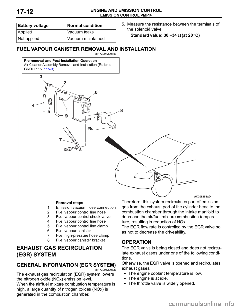
Battery voltageNormal condition
AppliedVacuum leaks
Not appliedVacuum maintained
EMISSION CONTROL
ENGINE AND EMISSION CONTROL17-12
5. Measure the resistance between the terminals of the solenoid valve.
Standard value: 30 − 34 Ω (at 20°C)
FUEL VAPOUR CANISTER RE MOVAL AND INSTALLATION
M1173004200153
Pre-removal and Post-installation Operation
Air Cleaner Assembly Removal and Installation (Refer to
GROUP 15
P.15-3).
AC208253
1
2
3
4 5 6
7 8
AD
Removal steps
1.Emission vacuum hose connection
2.Fuel vapour control line hose
3.Fuel vapour control check valve
4.Fuel vapour control line hose
5.Fuel vapour control line clamp
6.Fuel vapour canister
7.Fuel high-pressure hose clamp
8.Fuel vapour canister bracket
EXHAUST GAS RECIRCULA
T ION
(EGR) SYSTEM
GENERAL INFORMAT ION (EGR SYSTEM)
M1173 0052 0032 7
The exhaust gas recircu l atio n (EGR) system lowers
the nitrogen
oxide (NOx) emission level.
When the air/fuel mixture combus tio n temp erature is
high,
a larg e qua ntity of nitrogen oxides (NOx) is
generat
ed in the comb ustion chamb e r .
Therefor e, this syst em re circulat es p a rt o f emission
gas fro
m the e x ha ust po rt of the cylinder h ead to th e
combust
i on chamber thro ugh th e int a ke ma nifold to
decre
ase the air/fuel mixture combust i on te mpera
-
ture, resulting in redu ctio n of NOx.
The EGR flow rate is cont rolle d by the EGR valve so
as no
t to de crease the driveability .
OPERAT ION
The EGR valve is being clos ed an d does not re circu-
late ex hau st ga ses unde r one o f the fo llo wing condi-
tions.
Otherwise, th e EGR va lve is opene d an d recircul ates
exha
ust g a ses.
•The engine coolan t temperature is low .
•The engine is at idle.
•The throttle va lve is widely ope ned.
Page 273 of 800
42-1
GROUP 42
BODY
CONTENTS
HOOD . . . . . . . . . . . . . . . . . . . . .42-3
ON-VEHICLE SERVICE. . . . . . . . .42-3
ADJUSTMENT OF CLEARANCE
AROUND HOOD . . . . . . . . . . . . . . . . . . 42-3
ADJUSTMENT OF ALIGNMENT OF
HOOD STEPPED PORTION AND
HOOD STRIKER . . . . . . . . . . . . . . . . . . 42-3
ADJUSTMENT OF HOOD HEIGHT . . . 42-3
HOOD . . . . . . . . . . . . . . . . . . . . . . .42-4
REMOVAL AND INSTALLATION . . . . . 42-4
FENDER . . . . . . . . . . . . . . . . . . .42-5
SPECIAL TOOL . . . . . . . . . . . . . . .42-5
FENDER . . . . . . . . . . . . . . . . . . . . .42-6
REMOVAL AND INSTALLATION . . . . . 42-6
FUEL FILLER LID . . . . . . . . . . .42-8
REMOVAL AND INSTALLATION .42-8
STRUT TOWER BAR . . . . . . . .42-9
REMOVAL AND INSTALLATION .42-9
WINDOW GLASS . . . . . . . . . . . 42-10
ADHESIVE . . . . . . . . . . . . . . . . . . .42-10
SPECIAL TOOLS . . . . . . . . . . . . . .42-10
WINDOW REPAIR . . . . . . . . . . . . .42-10
WINDSHIELD . . . . . . . . . . . . . . . . .42-12
REMOVAL AND INSTALLATION . . . . . . 42-12
REAR WINDOW GLASS
REMOVAL AND INSTALLATION . . . . . . 42-17
QUARTER WINDOW GLASS
REMOVAL AND INSTALLATION . . . . . . 42-20
TAILGATE WINDOW GLASS
REMOVAL AND INSTALLATION . . . . . . 42-23
DOOR . . . . . . . . . . . . . . . . . . . . 42-25
SERVICE SPECIFICA TIONS . . . . .42-25
SEALANT . . . . . . . . . . . . . . . . . . . .42-25
SPECIAL TOOLS . . . . . . . . . . . . . .42-26
Continued on next page
Page 280 of 800
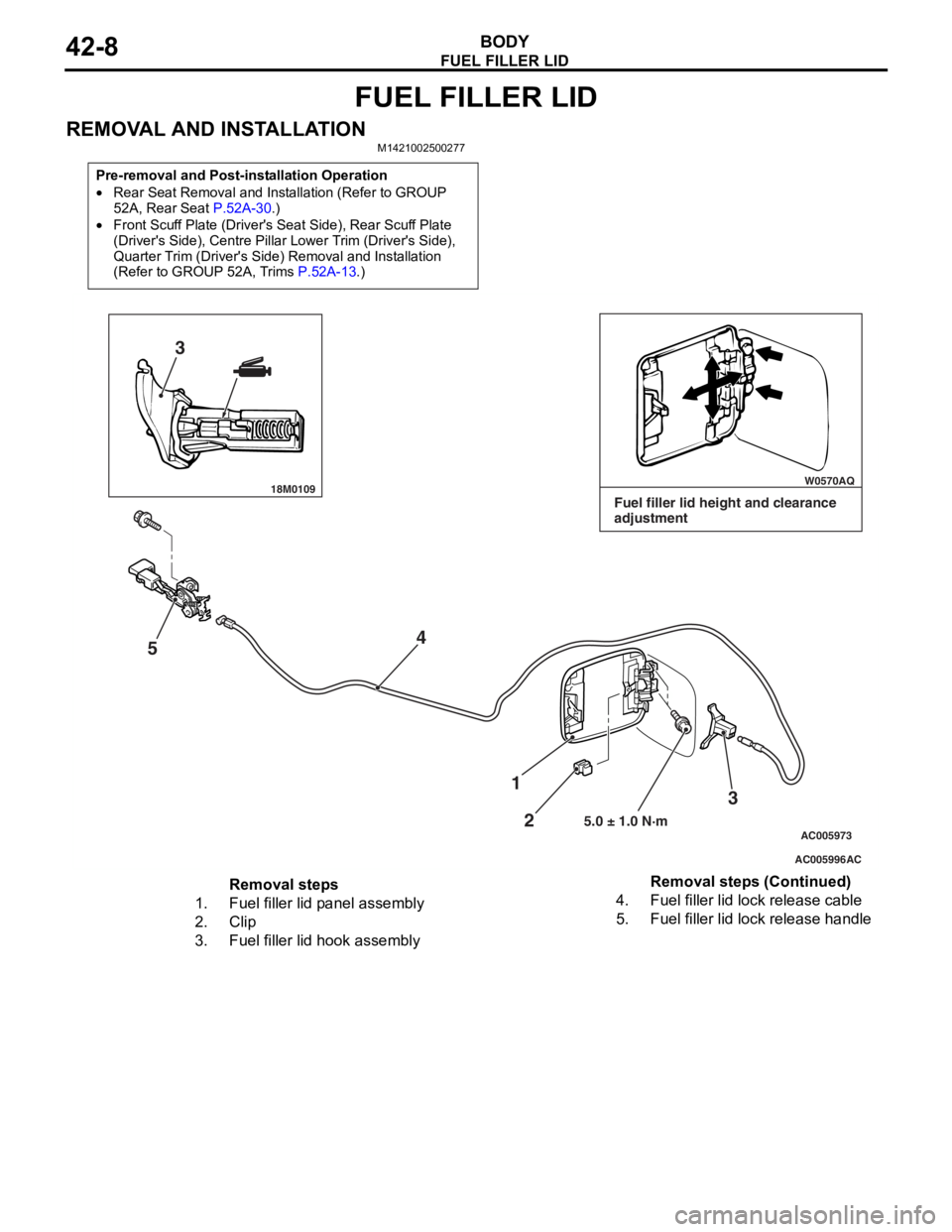
FUEL FILLER LID
BODY42-8
FUEL FILLER LID
REMOVAL AND INSTALLATIONM1421002500277
Pre-removal and Post-installation Operation
•Rear Seat Removal and Installation (Refer to GROUP
52A, Rear Seat
P.52A-30.)
•Front Scuff Plate (Driver's Seat Side), Rear Scuff Plate
(Driver's Side), Centre Pillar Lower Trim (Driver's Side),
Quarter Trim (Driver's Side) Removal and Installation
(Refer to GROUP 52A, Trims
P.52A-13.)
18M0109 W0570AQ
AC005996
AC005973
3
5 4
3
2
1
5.0 ± 1.0 N·m
AC
Fuel filler lid height and clearance
adjustment
Removal steps
1.Fuel filler lid panel assembly
2.Clip
3.Fuel filler lid hook assembly
4.Fuel filler lid lock release cable
5.Fuel filler lid lock release handle
Removal steps (Continued)
Page 395 of 800
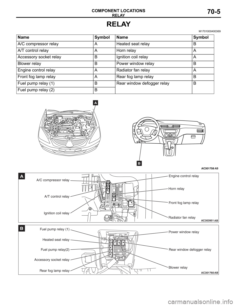
RELAY
COMPONENT LOCATIONS70-5
RELAY
M1701000400369
NameSymbolNameSymbol
A/C compressor relayAHeated seat relayB
A/T control relayAHorn relayA
Accessory socket relayBIgnition coil relayA
Blower relayBPower window relayB
Engine control relayARadiator fan relayA
Front fog lamp relayARear fog lamp relayB
Fuel pump relay (1)BRear window defogger relayB
Fuel pump relay (2)B
AC301758AB
A
B
AC303951AB
A/C compressor relayEngine control relay
Horn relay
Front fog lamp relay
Radiator fan relay
A/T control relay
Ignition coil relayA
AC301760
Fuel pump relay (1) Power window relay
Rear window defogger relay
Blower relay
Heated seat relay
Fuel pump relay(2)
Accessory socket relay
Rear fog lamp relayAB
B
Page 412 of 800

OVERALL CONFIGURATION DIAGRAM
CONFIGURATION DIAGRAMS80-2
OVERALL CONFIGURATION DIAGRAM
OVERALL WIRING DIAGRAM
AC301175AB
Front wiring
harness (RH) Control wiring
harness Instrument panel
wiring harness Roof wiring
harnessFloor wiring
harness (RH)
Battery wiring
harness Front wiring
harness (LH) Front door
wiring harness
Floor wiring
harness (LH) Fuel wiring
harnessRear door
wiring harness
Front bumper
wiring harness
Rear bumper
wiring harness
*
*
NO
TE: .
1.This illu stration shows o n ly major wirin g harne sses.
2.*: also eq uipp ed at t he rig h t side.
Page 413 of 800
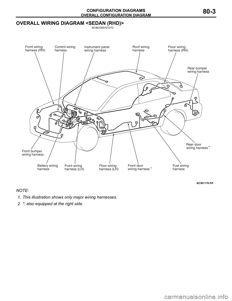
OVERALL CONFIGURATION DIAGRAM
CONFIGURATION DIAGRAMS80-3
OVERALL WIRING DIAGRAM
M1801000101272
AC301176AB
Front wiring
harness (RH) Control wiring
harness Instrument panel
wiring harness Roof wiring
harnessFloor wiring
harness (RH)
Battery wiring
harness Front wiring
harness (LH) Front door
wiring harness
Floor wiring
harness (LH) Fuel wiring
harnessRear door
wiring harness
Front bumper
wiring harness
Rear bumper
wiring harness
*
*
NO
TE: .
1.This illu stration shows o n ly major wirin g harne sses.
2.*: also eq uipp ed at t he rig h t side.
Page 414 of 800
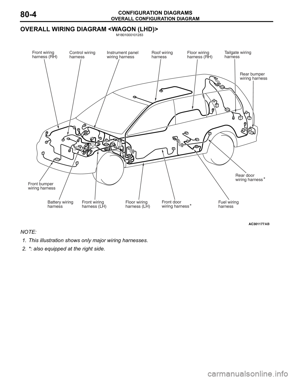
OVERALL CONFIGURATION DIAGRAM
CONFIGURATION DIAGRAMS80-4
OVERALL WIRING DIAGRAM
M1801000101283
AC301177AB
Front wiring
harness (RH)Control wiring
harness Instrument panel
wiring harness Roof wiring
harnessFloor wiring
harness (RH)
Battery wiring
harness Front wiring
harness (LH) Front door
wiring harness
Floor wiring
harness (LH) Fuel wiring
harnessRear door
wiring harness
Front bumper
wiring harness
Rear bumper
wiring harness
*
*
Tailgate wiring
harness
NO
TE: .
1.This illu stration shows o n ly major wirin g harne sses.
2.*: also eq uipp ed at t he rig h t side.
Page 415 of 800
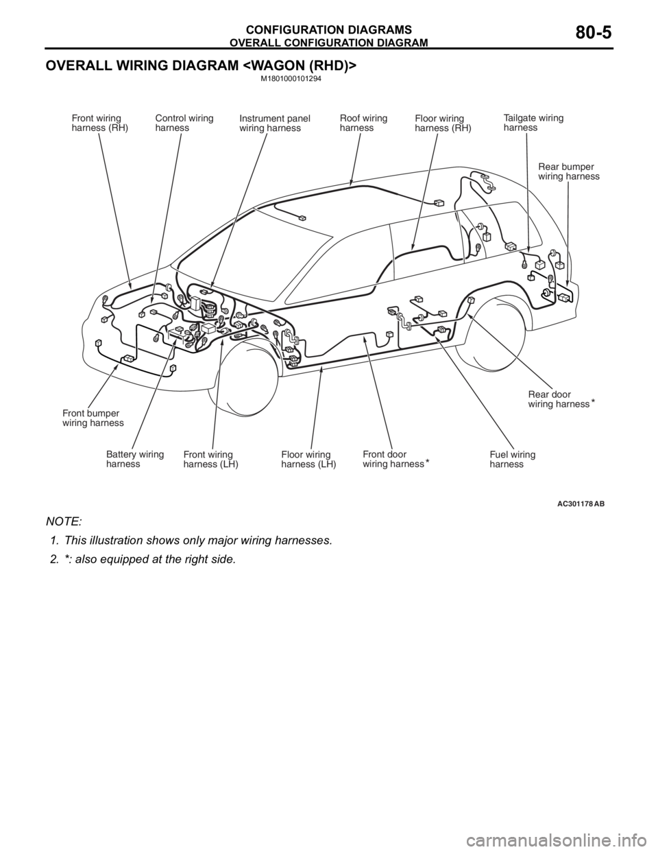
OVERALL CONFIGURATION DIAGRAM
CONFIGURATION DIAGRAMS80-5
OVERALL WIRING DIAGRAM
M1801000101294
AC301178AB
Front wiring
harness (RH)Control wiring
harness Instrument panel
wiring harness Roof wiring
harnessFloor wiring
harness (RH)
Battery wiring
harness Front wiring
harness (LH) Front door
wiring harness
Floor wiring
harness (LH) Fuel wiring
harnessRear door
wiring harness
Front bumper
wiring harness
Rear bumper
wiring harness
*
*
Tailgate wiring
harness
NO
TE: .
1.This illu stration shows o n ly major wirin g harne sses.
2.*: also eq uipp ed at t he rig h t side.