wiper MITSUBISHI LANCER 2006 User Guide
[x] Cancel search | Manufacturer: MITSUBISHI, Model Year: 2006, Model line: LANCER, Model: MITSUBISHI LANCER 2006Pages: 800, PDF Size: 45.03 MB
Page 364 of 800
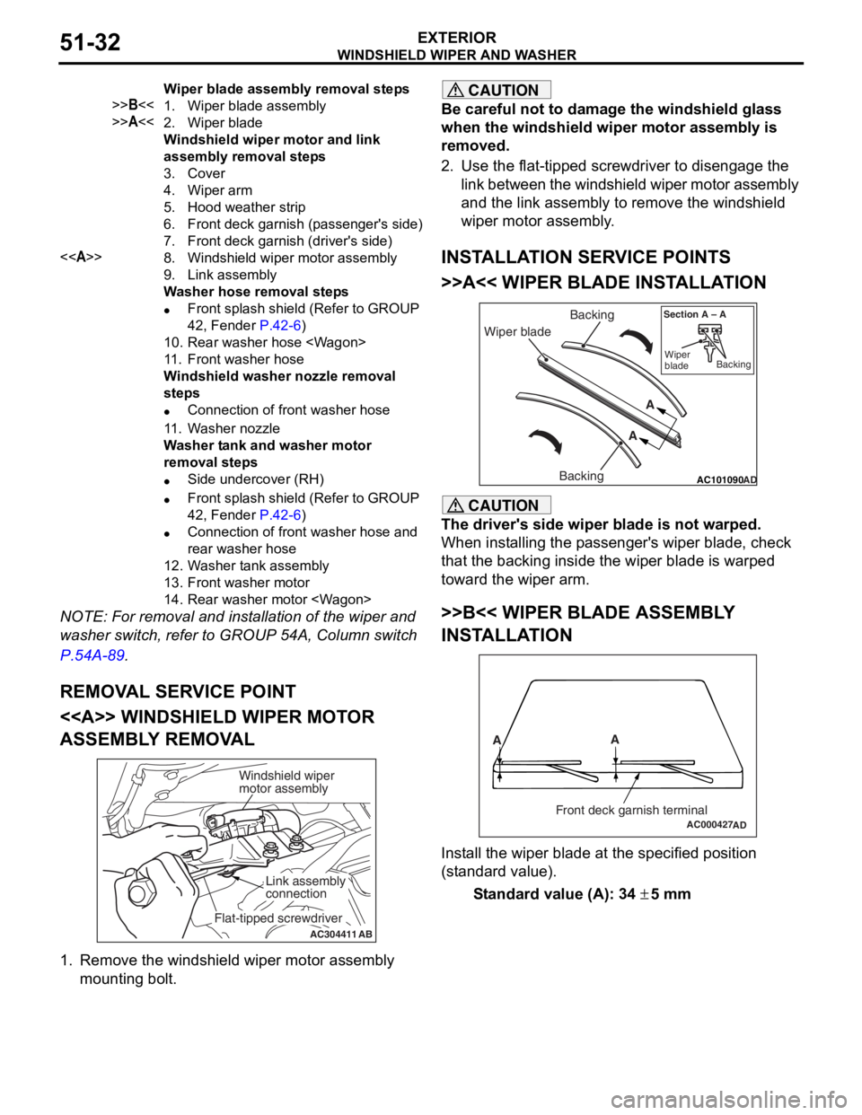
Wiper blade assembly removal steps
>>B<<1.Wiper blade assembly
>>A<<2.Wiper blade
Windshield wiper motor and link
assembly removal steps
3.Cover
4.Wiper arm
5.Hood weather strip
6.Front deck garnish (passenger's side)
7.Front deck garnish (driver's side)
<>8.Windshield wiper motor assembly
9.Link assembly
Washer hose removal steps
•Front splash shield (Refer to GROUP
42, Fender
P.42-6)
10.Rear washer hose
11 .Front washer hose
Windshield washer nozzle removal
steps
•Connection of front washer hose
11 .Washer nozzle
Washer tank and washer motor
removal steps
•Side undercover (RH)
•Front splash shield (Refer to GROUP
42, Fender
P.42-6)
•Connection of front washer hose and
rear washer hose
12.Washer tank assembly
13.Front washer motor
14.Rear washer motor
WINDSHIELD W I PER AND W A SHER
EXTERIOR51-32
NOTE: For re moval a nd in st allation of the wiper an d
washer switch, refer to GROUP 54A, Colu mn switch
P.5 4 A - 89.
REMOV A L SER V ICE POINT
<> WI NDSHIELD W I PER MOT O R
ASSEMBL
Y REMOV A L
AC304411AB
Windshield wiper
motor assembly
Link assembly
connection
Flat-tipped screwdriver
1.
Remove the win d shield wiper motor asse mbly
mounting bo lt.
CAUTION
Be careful not to damage the windshield glass
when the windshield wiper motor assembly is
removed.
2. Use the flat-tipped screwdriver to disengage the link between the windshield wiper motor assembly
and the link assembly to remove the windshield
wiper motor assembly.
INSTALLATION SERVICE POINTS
>>A<< WIPER BLADE INSTALLATION
AC101090 AD
Wiper blade Backing
Backing A
A
Section A – A
Wiper
blade Backing
CAUTION
The driver's side wiper blade is not warped.
When installing the passenger's wiper blade, check
that the backing inside the wiper blade is warped
toward the wiper arm.
>>B<< WIPER BLADE ASSEMBLY
INSTALLATION
AC000427
A
A
Front deck garnish terminalAD
Install the wiper blade at the specified position
(standard value).
Standard value (A): 34 ± 5 mm
Page 365 of 800
WINDSHIELD WIPER AND WASHER
EXTERIOR51-33
INSPECTION
M1511007700313
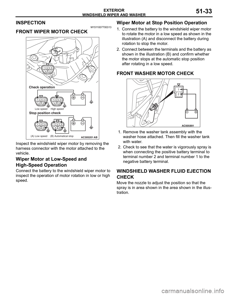
FRONT WIPER MOTOR CHECK
14 23
5
14 23
514 23
5
14 23
5
AC305201
14 23
5
Check operation
Low speed High speed
(A) Low speed (B) Automatical stop
Stop position check
AB
Inspe c t th e windshie l d wipe r mot o r by removing the
harness connector wit
h the motor a t t a ched to the
vehicle
.
Wiper Motor at Low-S peed and
High-S
peed Operation
Connect the ba ttery to the windsh i eld wiper motor to
insp
ect the ope ration of motor rot a tion in low or high
spee
d.
Wiper Motor at S t op Position Operation
1.Conn ect t he batt e ry to the wind shield wip e r mot o r
to rot a te th e motor in a low sp eed a s shown in the
illu stration (A) an d disco nnect the ba ttery durin g
ro t a tion to stop the motor .
2.Co nn ect b e t w ee n t h e te rmin als an d the b a tt ery as
shown in the illu strat i on (B) a nd co nfirm whether
th e mo tor sto p s at th e auto m atic stop po sition
a f ter rot a ting in a low sp eed.
FRONT WA SHER MOT O R CHECK
1
2
AC005891
1.Remove t he wash er t ank assembly wit h the
washer hose att a ched. T hen fill t he wash er t ank
with wa ter .
2.Check to see that th e wa ter is vigo rously sp ray is
when conn ecting the positive batt e ry te rmin al to
termina l number 2 and te rmin al nu mber 1 to th e
neg ative batt e ry te rmin al.
WI NDSHIELD W A SHER FLUID EJECTION
CHECK
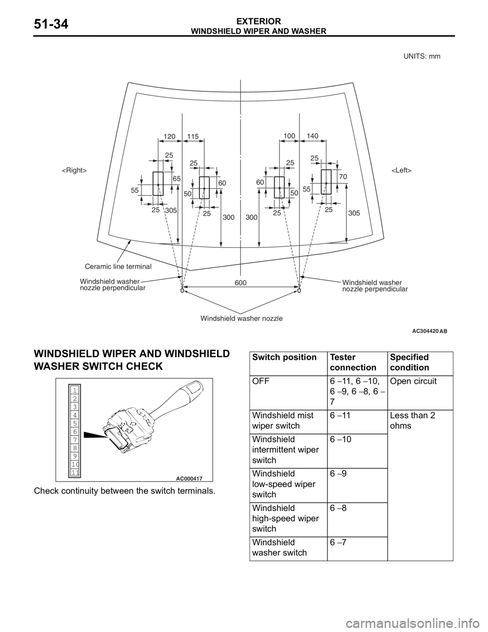
Move the nozzle to adjust th e position so that th e
spray is in a
r ea shown in the are a sh own in t he illus
-
tration.
Page 366 of 800
AC304420
305
70
25
55 140
100
120 115
305 300
600
3002525
25
25
25
25
25
55
6560
50
60
50
AB
Windshield washer
nozzle perpendicular
Windshield washer
nozzle perpendicular
Windshield washer nozzle
Ceramic line terminal
UNITS: mm
WINDSHIELD WI PER AND W A SHER
EXTERIOR51-34
WI NDSHIELD W I PER AND WINDSHIELD
W
A SHER SWIT CH CHECK
1
6
8
11 10 9 7
5 4
3
2
AC000417
Che
c k cont inuity be tween th e switch ter m in als.
Switch positionTester
connectionSpecified
condition
OFF6 − 11 , 6 − 10,
6 − 9, 6 − 8, 6 −
7
Open circuit
Windshield mist
wiper switch6 − 11Less than 2
ohms
Windshield
intermittent wiper
switch6 − 10
Windshield
low-speed wiper
switch6 − 9
Windshield
high-speed wiper
switch6 − 8
Windshield
washer switch6 − 7
Page 367 of 800
REAR WIPER AND WASHER
EXTERIOR51-35
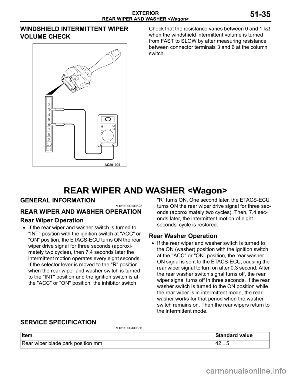
WINDSHIELD INTERMITTENT WIPER
VOLUME CHECK
1
6
8
11 10 9 7 5 4 3
2
AC201004
Ch
eck tha t the resist ance varie s between 0 a nd 1 kΩ
wh
en the
windshield int
e
rmittent volume is turn
ed
from F
A
ST
to SLOW by a
f
te
r mea
s
uring resist
an
ce
between conne
ctor
terminals 3 an
d 6 at
the column
switc
h
.
REAR WIPER AND W A SHER
GENERAL INFORMAT IONM151 1 0001 0052 5
REAR WIPER AND W A SHER OPERA T ION
Rear W i p e r O p eration
•If the rear wiper and washe r switch is turne d to
"INT" position
wit h th e ignition switch at "ACC" or
"ON" po
siti on, t he ET ACS-ECU t u rn s ON t he re ar
wipe
r drive signal for thre e se cond s (ap p roxi
-
mately two cycles), then 7 . 4 se cond s la ter the
int
e rmit tent mot i on o perates every eigh t seco nds.
If th
e se lector lever is moved to the "R" p o sition
when t
he rear wiper an d washe r switch is turn ed
to t
he "INT" position an d the ignit i on switch is at
the
"ACC" or "ON" positio n, the inhibito r switch "R" tu rns ON. One second late r , the ET ACS-ECU
turn s ON th e rear wip e r drive signal for thre e sec
-
ond
s (ap p roximat e ly two cycle s ). Th en, 7.4 sec-
onds later , th e inte rmittent motio n of eight
sec
o nds ' cy cle is restored.
Rear W a sher Operatio n
•If the rear wiper and washe r switch is turne d to
the
ON (washer) position wi th the ignition switch
at t
he "ACC" or "ON" po sit i on, t he rear wa sher
ON signal is sent to the ET
ACS-ECU, causing the
re
ar wipe r sign al to tu rn on a f ter 0 . 3 seco nd . Af te r
the
rear washer switch sign al tu rns o f f, the rear
wipe
r signa l t u rns of f in thre e seco nds. If the rear
washer switch is tu
rned to the ON position while
the
rear wipe r is in intermitten t mod e , the rear
washer works for th
at period when the washer
switch
rema ins on. Then the rea r wipe rs ret u rn to
the
intermitte nt mode.
SERV ICE SPECIFICA T ION
M151 1 0003 0033 6
ItemStandard value
Rear wiper blade park position mm42 ± 5
Page 368 of 800
REAR WIPER AND WASHER
EXTERIOR51-36
TROUBLESHOOTING
M1511000700334
The rear wiper and washer are controlled by the
Smart Wiring System (SWS). For troubleshooting,
refer to GROUP 54B, Troubleshooting
P.54B-15 or
GROUP 54C, Troubleshooting P.54C-4.
ON-VEHICLE SERVICE
M1511000800472
CHECK OF REAR WIPER OPERATION
WHEN SELECTOR LEVER IS AT THE "R"
POSITION
1. When the selector lever is moved to the "R" position with the rear wiper switch at the "INT"
position, the wiper should operate twice or three
times at low speed after approximately one
second.
2. If not, carry out the troubleshooting (Refer to GROUP 54B, Troubleshooting
P.54B-15 or
GROUP 54C, Troubleshooting P.54C-4).
REAR WIPER AND WASHER
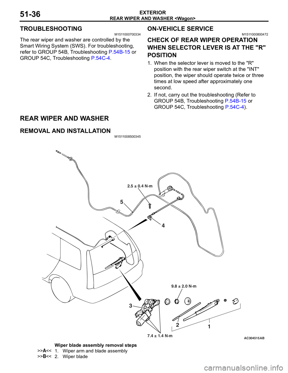
REMOVAL AND INSTALLATIONM1511008500345
AC304515
2.5 ± 0.4 N·m
9.8 ± 2.0 N·m
7.4 ± 1.4 N·m
3 2
1
4
5
AB
Wiper blade assembly removal steps
>>A<<1.Wiper arm and blade assembly
>>B<<2.Wiper blade
Page 369 of 800
Rear wiper motor removal steps
•Tailgate trim lower (Refer to GROUP
52A, Tailgate trim
P.52A-21.)
•Tailgate waterproof film (Refer to
GROUP 42, Tailgate
P.42-48.)
3.Rear wiper motor assembly
Rear washer nozzle removal steps
•High-mounted stop lamp assembly
(Refer to GROUP 54A, High-mounted
stop lamp
P.54A-84.)
4.Rear washer nozzle
Washer hose removal steps
•Front scuff plate, rear scuff plate, cowl
side trim and quarter trim (Refer to
GROUP 52A, Trims
P.52A-13.)
•Tailgate lower trim, tailgate proof film
(Refer to GROUP 52A, Tailgate trim
P.52A-21.)
•High-mounted stop lamp assembly
(Refer to GROUP 54A, High-mounted
stop lamp
P.54A-84.)
5.Rear washer hose
REAR WIPE R AN D W A SHER
EXTERIOR51-37
NOTE: For re moval a nd in st allation of the wiper an d
washer switch, refer to GROUP 54A, Colu mn switch
P.5 4 A - 89.
INSTALLA T ION SER VICE POINT S
>>A<< REAR WIPER ARM AND BLADE
ASSEMBL
Y INST ALLA TION
AC304536
A
AC
End of tailgate glass
Before inst alling the rear wiper arm and blad e
assembly
, ope rate the rear wip e r mo tor so that th e
motor stop
s at the predete r min ed p a rk position .
Inst
all the re ar wipe arm a nd blade assembly and
adjust the
rear wipe r blad e positio n so t hat the blad e
end stop
s at the pre determined positio n (st anda rd
position
) .
St andard va lue (A): 42 ± 5 mm
>>B<< W I PER BLADE INST ALLA TION
AC101090AD
Wiper blade Backing
Backing A
A
Section A – A
Wiper
blade Backing
CAUTION
Use a curved backing like that shown for the
backing of a wiper blade to ensure sustained
wiper wiping performance.
INSPECTION
M1511008600193
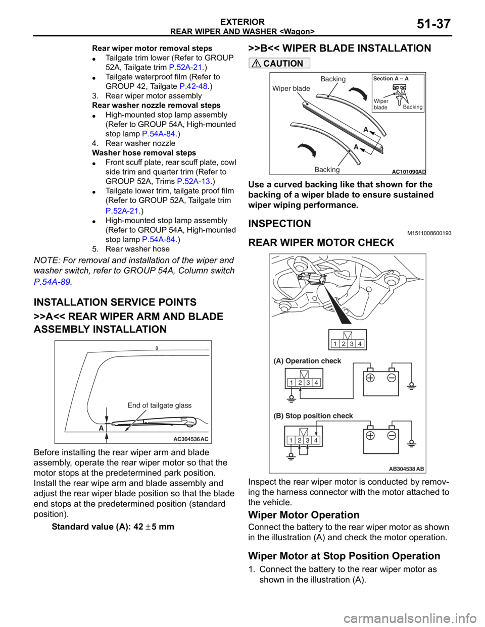
REAR WIPER MOTOR CHECK
AB304538
1234
1234
1234
AB
(A) Operation check
(B) Stop position check
Inspect the rear wiper motor is conducted by remov-
ing the harness connector with the motor attached to
the vehicle.
Wiper Motor Operation
Connect the battery to the rear wiper motor as shown
in the illustration (A) and check the motor operation.
Wiper Motor at Stop Position Operation
1. Connect the battery to the rear wiper motor as
shown in the illustration (A).
Page 370 of 800

REAR WIPER AND WASHER
EXTERIOR51-38
2. Disconnect the battery cable from the rear windshield wiper motor while it is turning and then
check to see that the motor stops.
3. Re-connect the battery as shown in Figure (B).
4. Check to see that the rear windshield wiper motor runs and then stops at the automatic stop
position.
REAR WASHER MOTOR CHECK
1
2
AC005900
1.Remo ve th e rear washer t ank assembly with th e
wash er hose att a ched. T hen fill t he wash er t ank
with wa ter .
2.Check to see t hat t he wate r is vigor ously spra yed
when conn ecting the positive batt e ry te rmin al to
termina l number 2 and te rmin al nu mber 1 to th e
neg ative batt e ry te rmin al.
REAR WA SHER FLUI D EJECTION CHECK
CAUTION
Take care not to damage the nozzle when insert-
ing the flat-tipped screwdriver into it.
AC304544AC
Unit: mm
57 84 125
6
Section A – A
A
A
High-mounted
stop lamp Rear washer nozzle
Flat-tipped screwdriverCeramic line terminal
Washer nozzle
perpendicular
For the vertical aiming of washer nozzle, insert the
flat-tipped screwdriver into the nozzle and move it to
the arrow direction.
REAR WIPER AND WASHER SWITCH
CHECK
1
6
8
11 10 9 7
5 4
3
2
AC000417
Check continuity between the switch terminals.
Switch positionTester
connectionSpecified
condition
OFF4 − 6, 5 − 6Open circuit
Rear wiper switch4 − 6Less than 2
ohms
Rear washer
switch5 − 6
Page 407 of 800
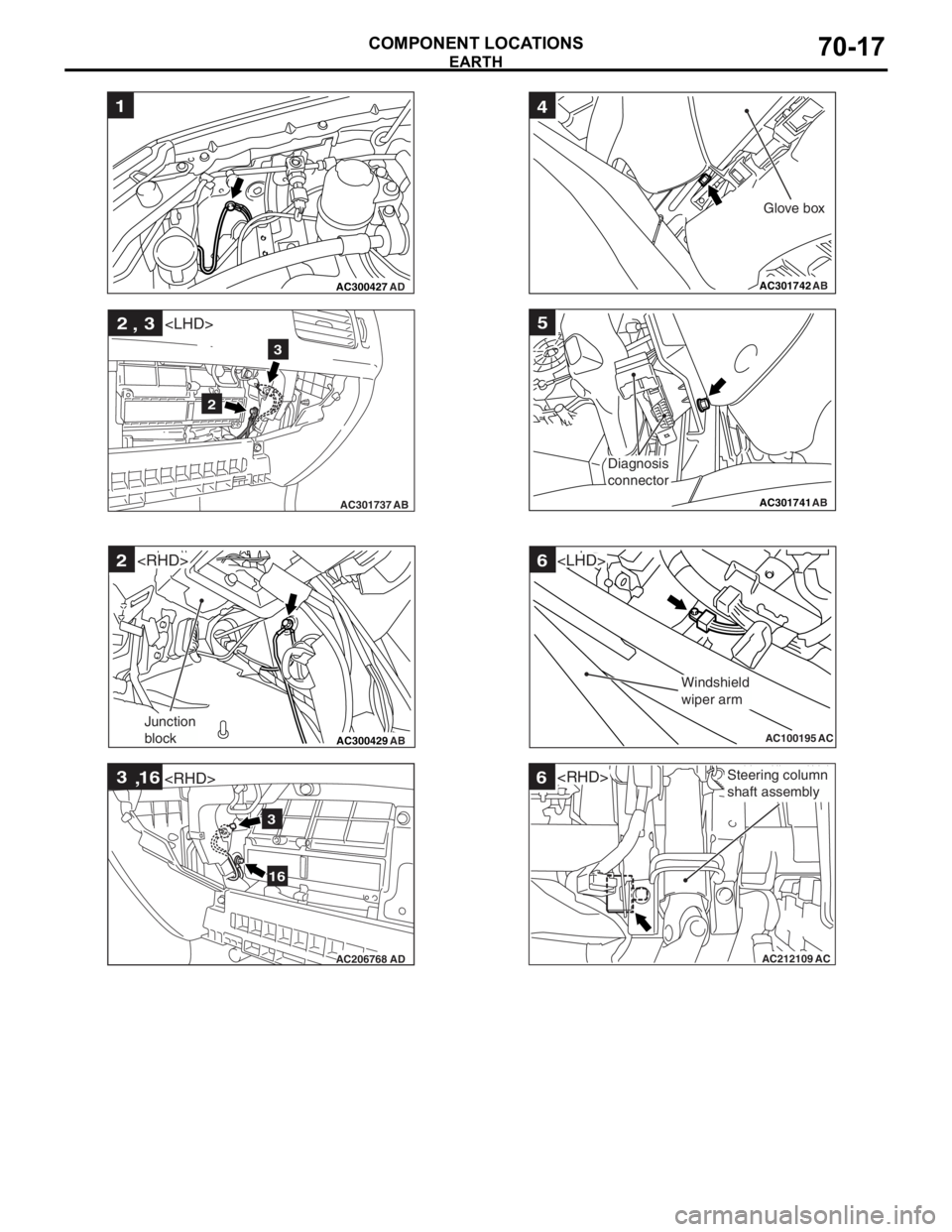
AC300427
1
AD
AC301737AB
2 3
,
2
3
AC300429 AB
2
Junction
block
AC206768 AD
3
16
,
3
16
AC301742 AB
4
Glove box
AC301741AB
5
Diagnosis
connector
AC100195
6
AC
Windshield
wiper arm
AC212109AC
6Steering column
shaft assembly
EARTH
COMPONENT LOCA
TIONS70-17
Page 408 of 800
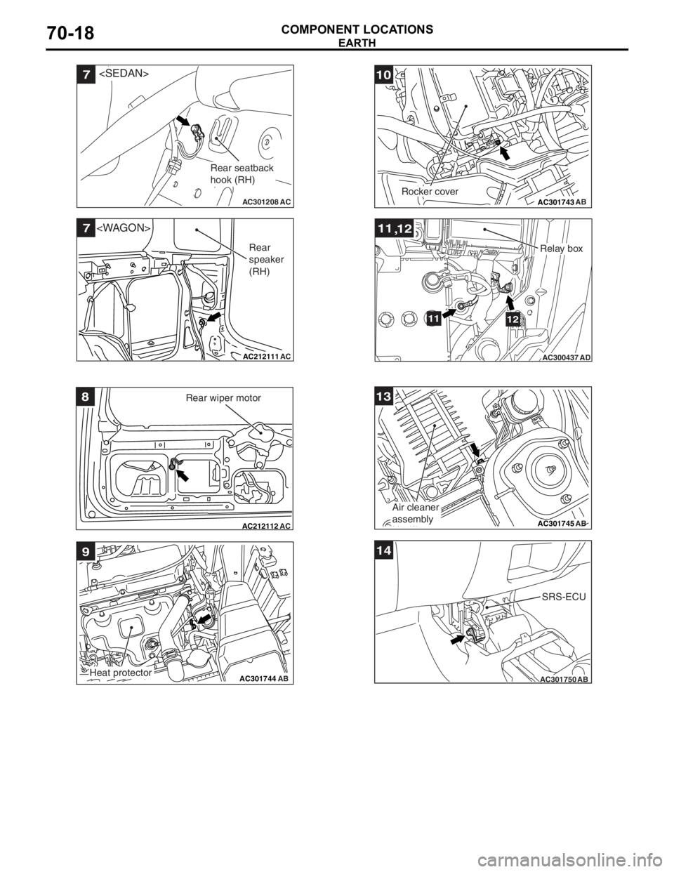
AC301208
7
AC
Rear seatback
hook (RH)
AC212111
7
AC
Rear
speaker
(RH)
AC212112AC
8Rear wiper motor
AC301744AB
9
Heat protector
AC301743AB
10
Rocker cover
AC300437
1112
,
1112
AD
Relay box
AC301745
13
AB
Air cleaner
assembly
AC301750AB
14
SRS-ECU
EARTH
COMPONENT LOCA TIONS70-18
Page 420 of 800
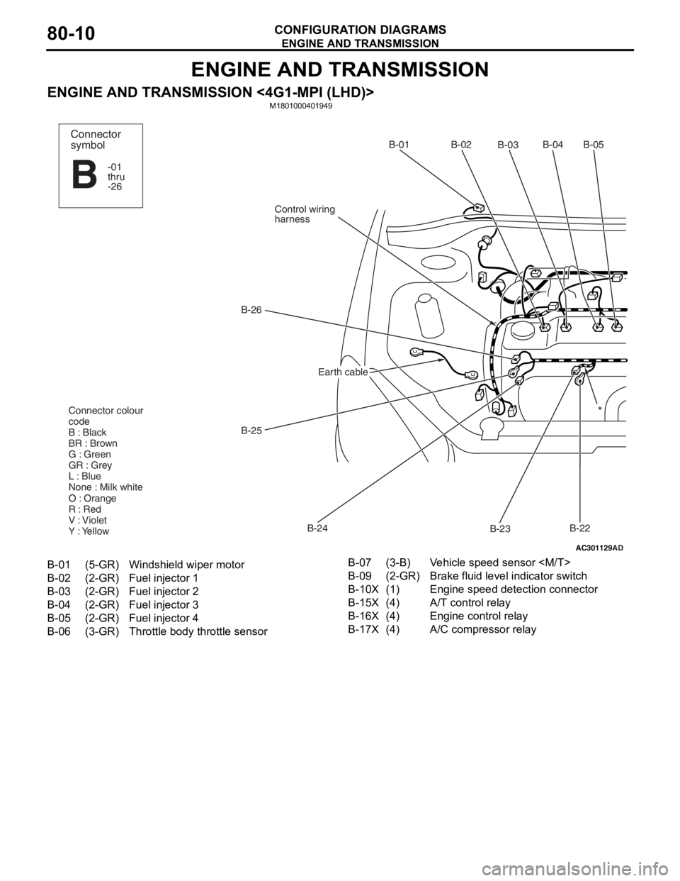
ENGINE AND TRANSMISSION
CONFIGURATION DIAGRAMS80-10
ENGINE AND TRANSMISSION
ENGINE AND TRANSMISSION <4G1-MPI (LHD)>M1801000401949
AC301129
AD
B-02
B-03B-04B-05
B-22
B-23
B-24
B-25
B-26
Control wiring
harnessB-01
Connector colour
code
B : Black
BR : Brown
G : Green
GR : Grey
L : Blue
None : Milk white
O : Orange
R : Red
V : Violet
Y : Yellow*
Connector
symbol
-01
thru
-26
B
Earth cable
B-01(5-GR)Windshield wiper motor
B-02(2-GR)Fuel injector 1
B-03(2-GR)Fuel injector 2
B-04(2-GR)Fuel injector 3
B-05(2-GR)Fuel injector 4
B-06(3-GR)Throttle body throttle sensor
B-07(3-B)Vehicle speed sensor
B-09(2-GR)Brake fluid level indicator switch
B-10X(1)Engine speed detection connector
B-15X(4)A/T control relay
B-16X(4)Engine control relay
B-17X(4)A/C compressor relay