control MITSUBISHI LANCER 2006 Repair Manual
[x] Cancel search | Manufacturer: MITSUBISHI, Model Year: 2006, Model line: LANCER, Model: MITSUBISHI LANCER 2006Pages: 800, PDF Size: 45.03 MB
Page 205 of 800
ON-VEHICLE SERVICE
REAR SUSPENSION34-7
Carry out adjustment by turning the toe adjusting bolt
(control link mounting bolt which is located on the
inner side of the body).
NOTE: .
•LH: Clockwise viewed from the front → To e - i n
•RH: Clockwise viewed from the front → Toe-out
•Turning the toe adjusting bolt by one groove of
the scale, toe can be changed approximately 2.6
mm (single side toe angle equivalent to 16').
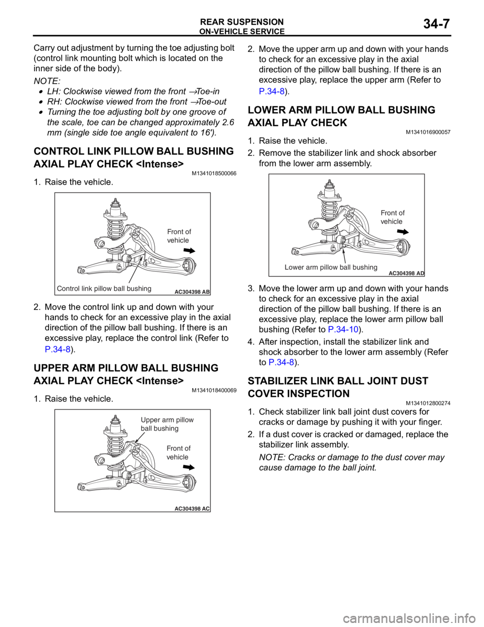
CONTROL LINK PILLOW BALL BUSHING
AXIAL PLAY CHECK
M1341018500066
1. Raise the vehicle.
AC304398ABControl link pillow ball bushing
Front of
vehicle
2.Move the control link up and d o wn with your
ha nds to ch eck for an excessive pla y in the a x ia l
direct ion o f the p illow ball bushing . If the r e is an
exce ssive play , re place the cont rol link (Re f er to
P.34-8).
UPPER ARM PILLOW BALL BUSHING
AXIAL PLAY CHECK
M13410184 0006 9
1.Raise th e ve hicle.
AC304398AC
Upper arm pillow
ball bushing
Front of
vehicle
2. Move the up per arm up and down with you r hand s
to che ck for an e xce ssive play in the axial
d i rection o f the p illow ball bushing . If the r e is an
e xce ssive play , re place the upper arm (Refe r to
P.34-8).
LOWER ARM PILLOW BALL BUSHING
AXIAL PLAY CHECK
M13410169 0005 7
1.Raise th e ve hicle.
2.Remove the st a b ilizer link and shock a b sorb er
f r om t h e l o we r arm a s s e mb l y .
AC304398ADLower arm pillow ball bushing
Front of
vehicle
3.Move the lower a r m u p and down with your h ands
to che ck for an e xce ssive play in the axial
d i rection o f the p illow ball bushing . If the r e is an
e xce ssive play , re place the lower a r m pillo w b a ll
b u shing (Refer to
P.34-10).
4.Af ter inspe c tio n , in st all the st a b ilizer link and
shock a b sorb er to the lower arm assembly (Refer
to
P.34-8).
STABILIZER LINK BALL JOINT DUST
COVER INSPECTION
M1341 0128 0027 4
1.Check st abilize r lin k ba ll joint dust covers f o r
cracks o r damage by pushing it wit h you r fing er .
2. If a du st cove r is crack ed or da mag ed, rep l ace t he
st a b ili zer link assembly .
NOTE: Cracks or dama ge to t he dust co ver may
cause damage to the b a ll join t.
Page 206 of 800
CONTROL LINK, UPPER ARM AND LOWER ARM
REAR SUSPENSION34-8
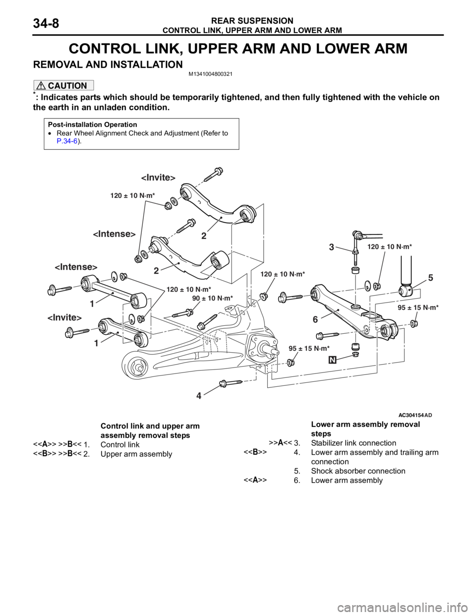
CONTROL LINK, UPPER ARM AND LOWER ARM
REMOVAL AND INSTALLATIONM1341004800321
CAUTION
*: Indicates parts which should be temporarily tightened, and then fully tightened with the vehicle on
the earth in an unladen condition.
Post-installation Operation
•Rear Wheel Alignment Check and Adjustment (Refer to
P.34-6).
AC304154
1 2
3
4 5
6
AD
120 ± 10 N·m*
95 ± 15 N·m*
120 ± 10 N·m*
120 ± 10 N·m*
95 ± 15 N·m*
90 ± 10 N·m* 120 ± 10 N·m*
N
Control link and upper arm
assembly removal steps
<>>>B<<1.Control link
<>>>B<<2.Upper arm assembly
Lower arm assembly removal
steps
>>A<<3.Stabilizer link connection
<>4.Lower arm assembly and trailing arm
connection
5.Shock absorber connection
<>6.Lower arm assembly
Page 207 of 800
Page 208 of 800
CONTROL LINK, UPPER ARM AND LOWER ARM
REAR SUSPENSION34-10
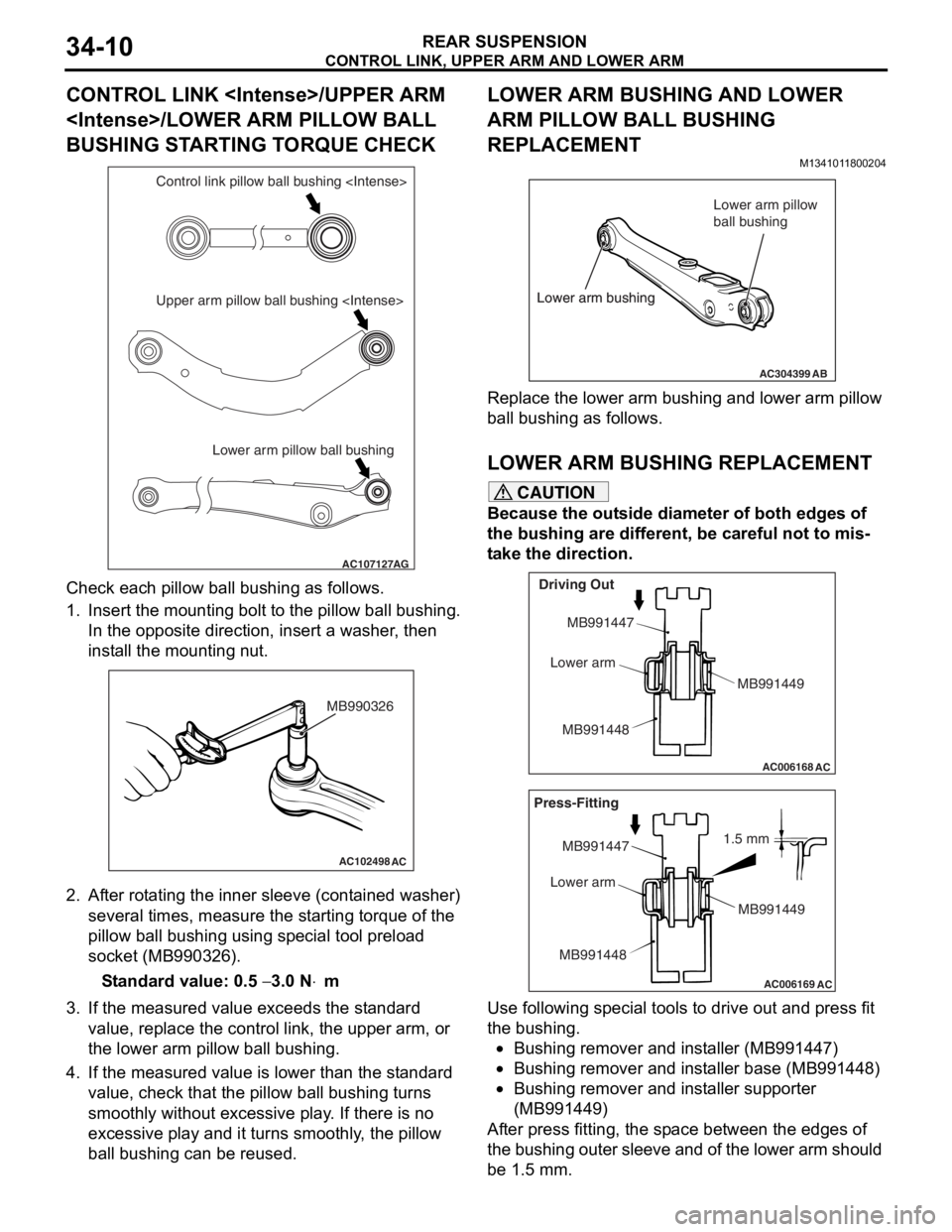
CONTROL LINK
BUSHING STARTING TORQUE CHECK
AC107127AG
Lower arm pillow ball bushing
Upper arm pillow ball bushing
Che
c k each pillow ball bu shing as follows.
1.In sert the mou n ting bo lt t o th e pillo w ball b u shing.
In the op posite direction, inse rt a wash er , the n
inst all the moun ting n u t.
AC102498AC
MB990326
2.Af ter rot a ting the inner sleeve (cont aine d washer)
seve ral times, me asure the st a r ting torque o f the
pillow ball bushing using sp ecial to ol pre l oad
socket (MB990326 ).
St andard va lue: 0.5 − 3.0 N⋅m
3.If the measu r ed value exceeds the st a ndard
value , replace the control lin k, the upper arm, o r
th e lower a r m pillo w ball bushing.
4.If the measu r ed value is lower tha n the st andard
value , che c k that th e pillow ba ll b u shing turn s
smoo thly withou t excessive play . If the r e is no
exce ssive play and it turns smooth l y , the pillow
ba ll b u shing can be reused.
LOWER ARM BUSHING AND LOWER
ARM PILLOW BALL BUSHING
REPLACEMENT
M134101 18 0020 4
AC304399AB
Lower arm bushing Lower arm pillow
ball bushing
Lower arm bushing
Re place the lower a r m bu shing an d lower arm p illow
ball bushing
as fo llows.
LO WER ARM BUSHING REPLACEM ENT
CAUTION
Because the outside diameter of both edges of
the bushing are different, be careful not to mis
-
take the direction.
AC006168
AC
Driving Out
MB991447
Lower arm
MB991448 MB991449
AC006169
AC
1.5 mm
Press-Fitting
MB991447
Lower arm
MB991448 MB991449
Use following special tools to drive out and press fit
the bushing.
•Bushing remover and installer (MB991447)
•Bushing remover and installer base (MB991448)
•Bushing remover and installer supporter
(MB991449)
After press fitting, the space between the edges of
the bushing outer sleeve and of the lower arm should
be 1.5 mm.
Page 209 of 800
CONTROL LINK, UPPER ARM AND LOWER ARM
REAR SUSPENSION34-11
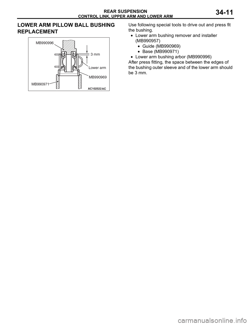
LOWER ARM PILLOW BALL BUSHING
REPLACEMENT
AC102522
AC
3 mm
MB990996
Lower arm
MB990971 MB990969
Use followin
g spe c ia l too l s t o drive ou t and p r ess fit
the bushin
g .
•Lower arm b u shing remove r and inst aller
(MB9
90957 )
•Guide (MB990969 )
•Base (MB99097 1)
•Lower arm b u shing arb o r (MB99 0996)
After p r ess fitting, t he sp ace bet we en the edges of
t
he bushin g ou ter sleeve and of the lower a r m sh ould
be 3 mm.
Page 210 of 800
TRAILING ARM ASSEMBLY
REAR SUSPENSION34-12
TRAILING ARM ASSEMBLY
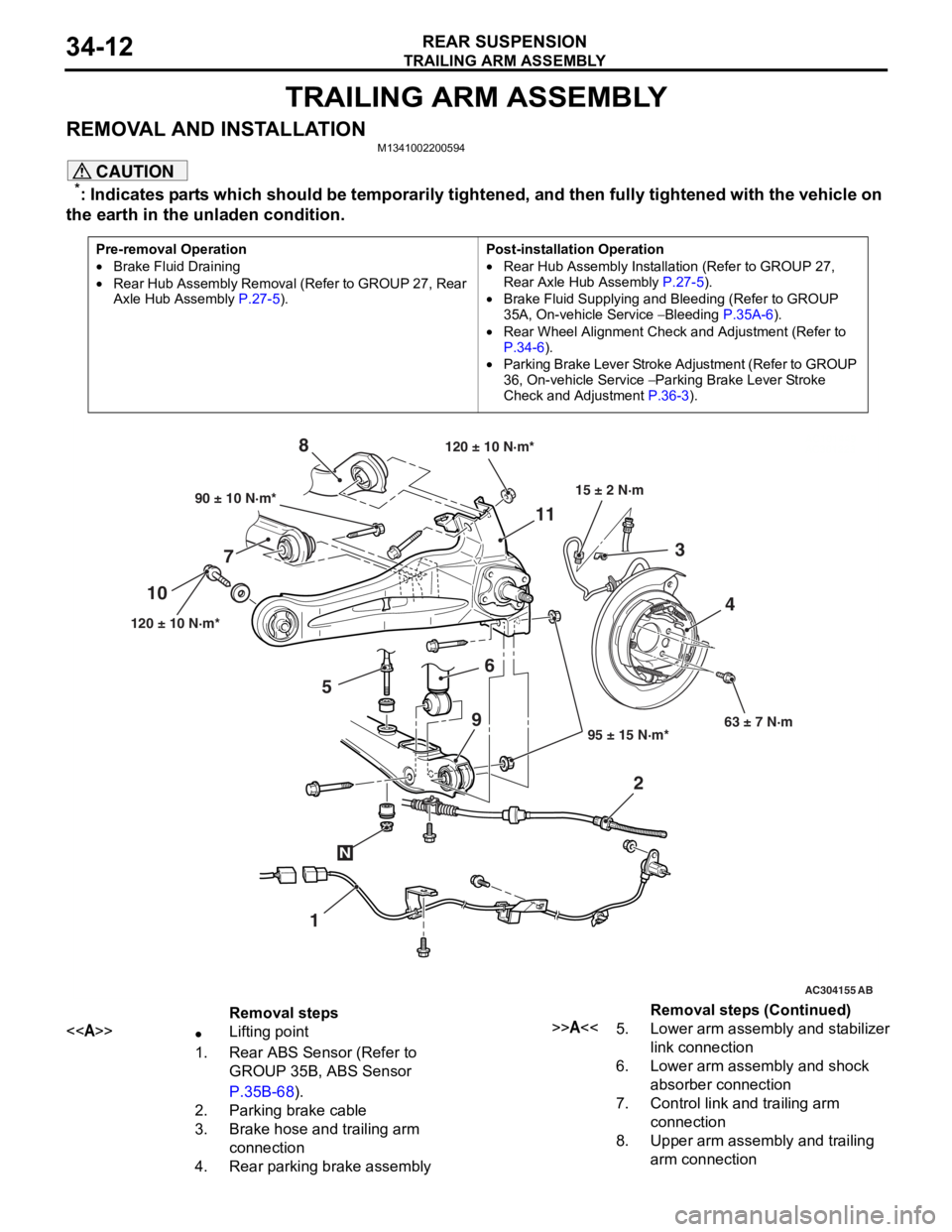
REMOVAL AND INSTALLATIONM1341002200594
CAUTION
*: Indicates parts which should be temporarily tightened, and then fully tightened with the vehicle on
the earth in the unladen condition.
Pre-removal Operation
•Brake Fluid Draining
•Rear Hub Assembly Removal (Refer to GROUP 27, Rear
Axle Hub Assembly P.27-5).
Post-installation Operation
•Rear Hub Assembly Installation (Refer to GROUP 27,
Rear Axle Hub Assembly
P.27-5).
•Brake Fluid Supplying and Bleeding (Refer to GROUP
35A, On-vehicle Service
− Bleeding P.35A-6).
•Rear Wheel Alignment Check and Adjustment (Refer to
P.34-6).
•Parking Brake Lever Stroke Ad justment (Refer to GROUP
36, On-vehicle Service
− Parking Brake Lever Stroke
Check and Adjustment
P.36-3).
AC101449
AC301223
AC304155 AB
90 ± 10 N·m*
120 ± 10 N·m* 95 ± 15 N·m*63 ± 7 N·m
6
7 8
1
10
11
23
4
120 ± 10 N·m*
15 ± 2 N·m
N
9
5
Removal steps
<>•Lifting point
1.Rear ABS Sensor (Refer to
GROUP 35B, ABS Sensor
P.35B-68).
2.Parking brake cable
3.Brake hose and trailing arm
connection
4.Rear parking brake assembly
>>A<<5.Lower arm assembly and stabilizer
link connection
6.Lower arm assembly and shock
absorber connection
7.Control link and trailing arm
connection
8.Upper arm assembly and trailing
arm connection
Removal steps (Continued)
Page 231 of 800
37-1
GROUP 37
POWER STEERING
CONTENTS
GENERAL INFORMATION . . . . . . . .37-3
SERVICE SPECIFICATIONS . . . . . . .37-6
LUBRICANTS . . . . . . . . . . . . . . . . . .37-7
SEALANTS . . . . . . . . . . . . . . . . . . . .37-7
SPECIAL TOOLS . . . . . . . . . . . . . . . .37-8
ON-VEHICLE SERVICE . . . . . . . . . . .37-11
STEERING WHEEL FREE PLAY CHECK . 37-11
STEERING ANGLE CHECK . . . . . . . . . . . . 37-11
TIE ROD END BALL JOINT TURNING
TORQUE CHECK . . . . . . . . . . . . . . . . . . . . 37-12
STATIONARY STEERING EFFORT
CHECK . . . . . . . . . . . . . . . . . . . . . . . . . . . . 37-12
STEERING WHEEL RETURN TO
CENTRE CHECK . . . . . . . . . . . . . . . . . . . . 37-13
DRIVE BELT TENSION CHECK. . . . . . . . . 37-13
FLUID LEVEL CHECK . . . . . . . . . . . . . . . . 37-13
FLUID REPLACEMENT . . . . . . . . . . . . . . . 37-13
POWER STEERING SYSTEM AIR
BLEEDING . . . . . . . . . . . . . . . . . . . . . . . . . 37-14
OIL PUMP PRESSURE TEST . . . . . . . . . . 37-14
POWER STEERING PRESSURE
SWITCH CHECK . . . . . . . . . . . . . . . . . . . . . 37-15
TIE ROD END BALL JOINT DUST
COVER CHECK . . . . . . . . . . . . . . . . . . . . . 37-15
STEERING COLUMN SHAFT ASSEMBLY
SHOCK ABSORBING MECHANISM
CHECK . . . . . . . . . . . . . . . . . . . . . . . . . . . . 37-15
STEERING WHEEL . . . . . . . . . . . . . .37-17
REMOVAL AND INSTALLATION
REMOVAL AND INSTALLATION
Continued on next page
WARNINGS REGARDING SERVICING OF SUPPLEMENTAL RESTRAINT SYSTEM (SRS) EQUIPPED VEHICLES
WARNING
•Improper service or maintenance of any component of the SRS, or any SRS-related component, can lead to
personal injury or death to service personnel (from inad vertent firing of the air bag) or to the driver and
paassenger (from renderin g the SRS inoperative).
•Service or maintenance of any SRS component or SRS-related component must be performed only at an
authorized MITSUBISHI dealer.
•MITSUBISHI dealer personnel must thoroughly review th is manual, and especially its GROUP 52B - Supplemental
Restraint System (SRS) before begi nning any service or maintenance of any component of the SRS or any
SRS-related component.
NOTE
The SRS includes the following components: SRS air bag control unit, SRS warning light, front impact sensors, air bag module,
clock spring, and interconnecting wiring. Other SRS-related components (that may have to be removed/installed in connection
with SRS service or maintenance) are indicated in the table of contents by an asterisk (*).
Page 233 of 800

GENERAL INFORMATION
POWER STEERING37-3
GENERAL INFORMATION
M1372000100661
Power steering has been adopted in all vehicles to
make the steering system easier to handle.
FEATURES
•A 4-spoke steering wheel is used.
•MOMO leather-wrapped 3-spoke steering wheel
is used.
•A steering column has a shock absorbing mecha-
nism and a tilt steering mechanism.
•Integral-type rack and pinion gear with high rigid-
ity and excellent response is used.
•A vane type pump with a fluid flow rate control
system which change steering effort according to
the engine speed is used.
•The separate plastic resin oil reservoir is used to
reduce weight and to make the fluid level check
-
ing easier.
SPECIFICATIONS
ItemInviteIntense
Steering
wheelTy p e4-spoke typeMOMO leather-wrapped
3-spoke type
Outside diameter mm380365
Maximum number of turns3.193.08
Steering
columnColumn mechanismShock absorbing mechanism and Tilt steering mechanism
Power steering typeIntegral type
Oil pumpTy p eVane pump
Basic discharge amount cm3/rev.7.2 <1300, 1600>
8.1 <2000>
7.2 <1300, 1600>
8.1 <2000>
Relief pressure MPa8.88.8
Reservoir typeSeparate type (plastic)
Pressure switchEquipped
Steering
gearTy p eRack and pinion
Stroke ratio (Rack stroke/Steering
wheel maximum turning radius)45.7445.74
Rack stroke mm146141
Page 244 of 800
ON-VEHICLE SERVICE
POWER STEERING37-14
POWER STEERING SYSTEM AIR
BLEEDING
M1372002200330
Perform air bleeding procedure as necessary after
replacing the steering gear or the steering fluid lines.
1. Raise and support the front wheels.
2. Disconnect the ignition coil connectors (Refer to GROUP 16, Ignition Coil
P.16-38 or P.16-39).
CAUTION
Perform air bleeding only while cranking the
engine. If air bleeding is performed while the
engine is running, air could enter the fluid. Dur
-
ing air bleeding, refill the steering fluid supply so
that the level never falls below the "MIN" mark on
the oil reservoir.
3. Turn the steering wheel all the way to the left and
right five or six times wh ile using the starter motor
to crank the engine intermittently several times
(for 15 to 20 seconds).
4. Connect the ignition coil connectors (Refer to GROUP 16, Ignition Coil
P.16-38 or P.16-39).
5. Start the engine (idling).
6. Turn the steering wheel to the left and right until there are no air bubbles in the oil reservoir.
7. Confirm that the fluid is not milky, and that the level is between "MAX" and "MIN" marks.
8. Confirm that there is very little change in the fluid
level when the steering wheel is turned left and
right.
CAUTION
If the fluid level rises suddenly after the engine is
stopped, the air has not been completely bled. If
air bleeding is not complete, there will be abnor
-
mal noises from the pump and the flow-control
valve, and this condition could cause reduce the
life of the power steering components.
ACX01131With engine running With engine stoppedAC
Fluid level change: Within 5 mm
9. Confirm that the change in the fluid level is no more than 5 mm when the engine is stopped and
when it is running.
10.If the change of the fluid level is 5 mm or more,
the air has not been completely bled from the
system. The air bleeding procedure must be
repeated.
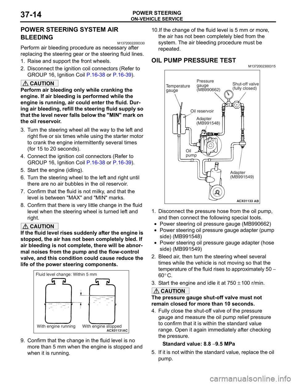
OIL PUMP PRESSURE TEST
M1372002300315
ACX01133
Temperature
gauge
Oil reservoir
Adapter
(MB991548)
Oil
pump Adapter
(MB991549)
AB
Shut-off valve
(fully closed)
Pressure
gauge
(MB990662)
1. Disconnect the pressure hose from the oil pump,
and then connect the following special tools.
•Power steering oil pressure gauge (MB990662)
•Power steering oil pressure gauge adapter (pump
side) (MB991548)
•Power steering oil pressure gauge adapter (hose
side) (MB991549)
2. Bleed air, then turn the steering wheel several times while the vehicle is not moving so that the
temperature of the fluid rises to approximately 50
−
60
°C.
3. Start the engine and idle it at 750 ± 100 r/min.
CAUTION
The pressure gauge shut-off valve must not
remain closed for more than 10 seconds.
4. Fully close the shut-off valve of the pressure gauge and measure the oil pump relief pressure
to confirm that it is within the standard value
range. Open it again immediately after checking
the pressure.
Standard value: 8.8 − 9.5 MPa
5. If it is not within the standard value, replace the oil pump.
Page 268 of 800
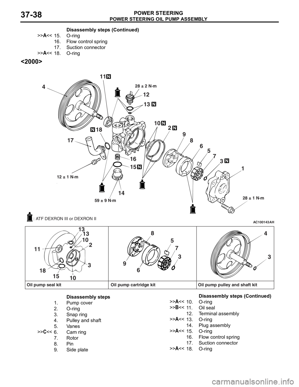
POWER STEERING OIL PUMP ASSEMBLY
POWER STEERING37-38
<2000>
AC100143AH
4 11
12
13
28 ± 2 N·m
102
9 8 65
7 3
1
28 ± 1 N·m
15
16
14
59 ± 9 N·m
12 ± 1 N·m
18
17
57
3
9 8
6
3
13
10 2
13
10
15
18
11
4
3
Oil pump seal kit Oil pump cartridge kit Oil pump pulley and shaft kit
: ATF DEXRON III or DEXRON II
Disassembly steps
1.Pump cover
2.O-ring
3.Snap ring
4.Pulley and shaft
5.Va n e s
>>C<<6.Cam ring
7.Rotor
8.Pin
9.Side plate
>>A<<10.O-ring
>>B<<11 .Oil seal
12.Terminal assembly
>>A<<13.O-ring
14.Plug assembly
>>A<<15.O-ring
16.Flow control spring
17.Suction connector
>>A<<18.O-ring
>>A<<15.O- rin g
16.Fl ow co n t ro l s p r i ng
17.Suction connector
>>A<<18.O-rin g
Disass embly st ep s ( C ont inu e d)
Disassembly steps (Continued)