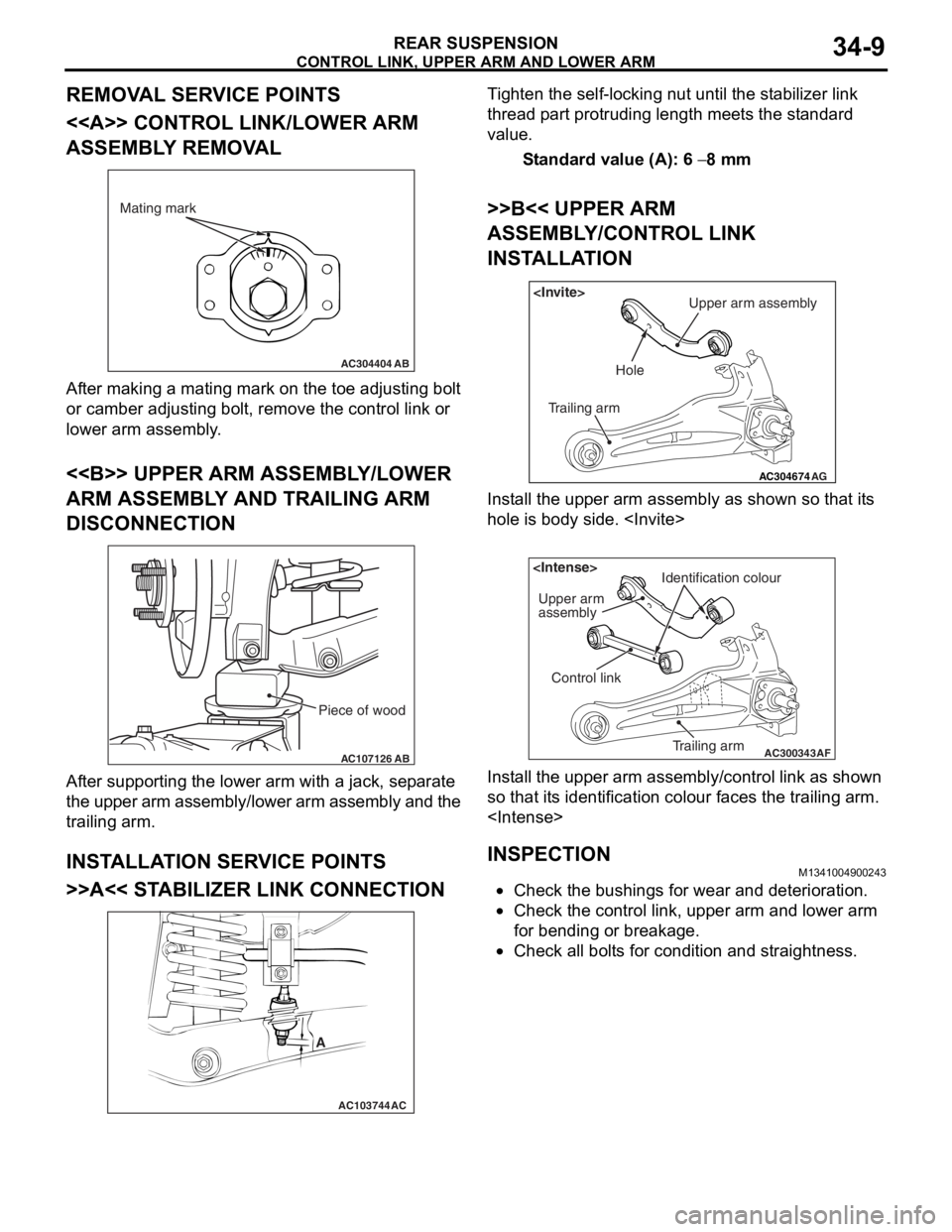
service MITSUBISHI LANCER 2006 Repair Manual
[x] Cancel search | Manufacturer: MITSUBISHI, Model Year: 2006, Model line: LANCER, Model: MITSUBISHI LANCER 2006Pages: 800, PDF Size: 45.03 MB
Page 191 of 800
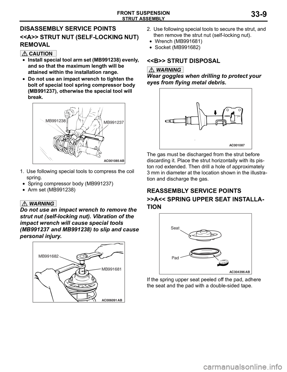
Page 193 of 800
LOWER ARM
FRONT SUSPENSION33-11
LOWER ARM
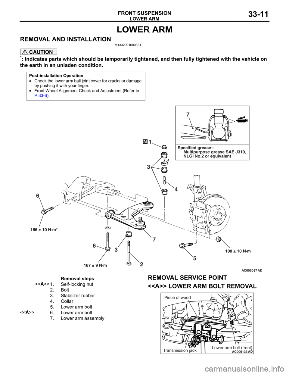
REMOVAL AND INSTALLATIONM1332001600331
CAUTION
*: Indicates parts which should be temporarily tightened, and then fully tightened with the vehicle on
the earth in an unladen condition.
Post-installation Operation
•Check the lower arm ball join t cover for cracks or damage
by pushing it with your finger.
•Front Wheel Alignment Check and Adjustment (Refer to
P.33-6).
AC006097 AD
7
1
3 4
5
108 ± 10 N·m
186 ± 10 N·m*
7
3
6
N
Specified grease :
Multipurpose grease SAE J310,
NLGI No.2 or equivalent
167 ± 9 N·m
6
2
Removal steps
>>A<<1.Self-locking nut
2.Bolt
3.Stabilizer rubber
4.Collar
5.Lower arm bolt
<>6.Lower arm bolt
7.Lower arm assembly
REMOVAL SERVICE POINT
<> LOWER ARM BOLT REMOVAL
AC006133
ADLower arm bolt (front)Transmission jackPiece of wood
Page 194 of 800
LOWER ARM
FRONT SUSPENSION33-12
As for the L.H. lower arm assembly, withdraw the
lower arm bolt (front) with the transmission lift up by
using a transmission jack.
INSTALLATION SERVICE POINT
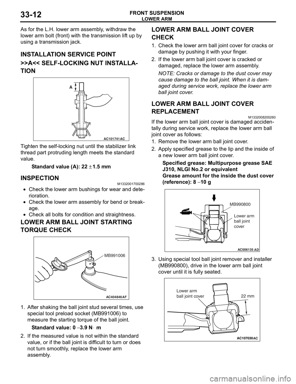
>>A<< SELF-LOCKING NUT INSTALLA-
TION
AC101741AC
A
T i ghten the self-locking nut un til t he st abilizer link
thread p
a rt protrud i ng length meet s the st a ndard
valu
e.
St andard va lue (A): 22 ± 1.5 m m
INSPECTION
M1332 0017 0028 6
•Check the lower arm bushing s for wear and det e-
riora t i o n.
•Check th e lo we r arm assemb ly for be nd or break-
age.
•Check all bo lt s for c ond ition and straightness.
LOWER ARM BALL JOINT ST ARTING
T
O RQUE CHECK
AC404846AF
MB991006
1.Af ter shaking the b a ll joint stud several times, use
special tool p r eloa d socke t (MB991 006) to
measure the st artin g torqu e of the ball joint.
St andard va lue: 0 − 3.9 N⋅m
2.If the measu r ed value is n o t within the st anda rd
value , or if the ba ll joint is dif f icu l t to t u rn or d oes
no t turn smo o thly , replace the lower a r m
asse mbly .
LOWER ARM BALL JOINT COVER
CHECK
1.Check t he lo we r arm b a ll joint co ver fo r cracks or
d a mag e by push i ng it with your finger .
2.If the lower arm ball joint co ver is cracked or
d a mag ed, rep l ace the lower arm assemb ly .
NOTE: Cracks or dama ge to t he dust co ver may
cause damage to the b a ll join t. When it is dam
-
aged du ring service wo rk, rep l ace the lower arm
b
a ll j o in t cover .
LOWER ARM BALL JOINT COVER
REPLACEMENT
M13320082 0026 0
If the lower arm ball jo int cove r is dama ged acciden-
ta lly durin g ser v ice work, repla c e th e lower arm b a ll
join
t cover as follows:
1.Remove the lower arm ball joint cover .
2.App l y specified grea se to the lip an d the inside of
a new lower arm ba ll join t cover .
Specified grease: Multipurpos e grease SAE
J310,
NLGI No.2 o r e quivale n t
Grease amount for the insi de the du st cove r
(re
f erence): 8
− 10 g
AC006135AD
MB990800
Lower arm
ball joint
cover
3. Using special tool ball joint remover and inst aller
(MB99080 0), drive in the lower arm ball jo int
cove r until it is fu lly se ated.
AC107030AC
22 mm
Lower arm
ball joint cover
Page 196 of 800
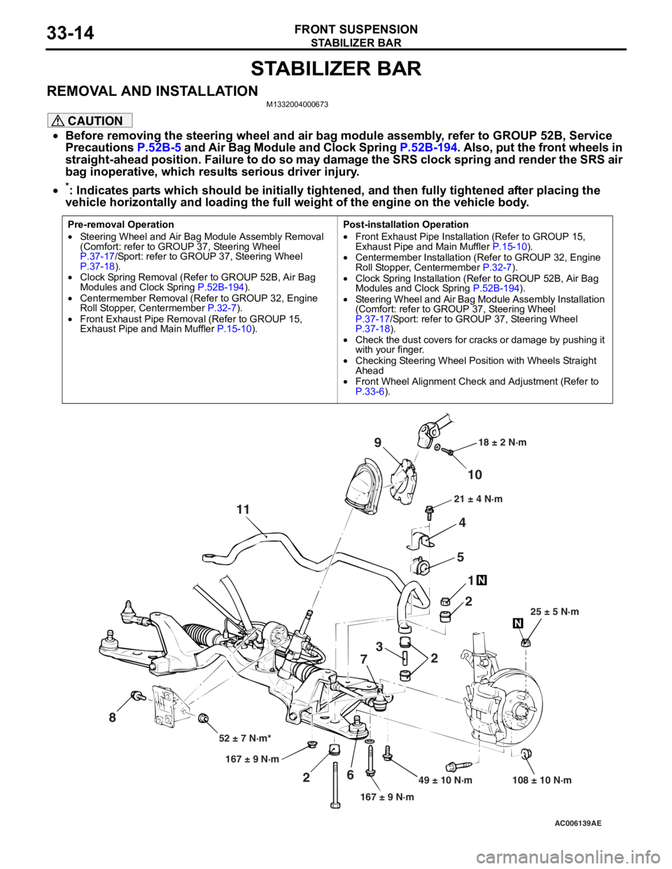
STABILIZER BAR
FRONT SUSPENSION33-14
STABILIZER BAR
REMOVAL AND INSTALLATIONM1332004000673
CAUTION
•Before removing the steering wheel and air bag module assembly, refer to GROUP 52B, Service
Precautions
P.52B-5 and Air Bag Module and Clock Spring P.52B-194. Also, put the front wheels in
straight-ahead position. Failure to do so may damage the SRS clock spring and render the SRS air
bag inoperative, which results serious driver injury.
•
Pre-removal Operation
•Steering Wheel and Air Bag Module Assembly Removal
(Comfort: refer to GROUP 37, Steering Wheel
P.37-17/Sport: refer to GROUP 37, Steering Wheel P.37-18).•Clock Spring Removal (Refer to GROUP 52B, Air Bag
Modules and Clock Spring P.52B-194).
•Centermember Removal (Ref er to GROUP 32, Engine
Roll Stopper, Centermember P.32-7).
•Front Exhaust Pipe Remova l (Refer to GROUP 15,
Exhaust Pipe and Main Muffler P.15-10).
Post-installation Operation
•Front Exhaust Pipe Installation (Refer to GROUP 15,
Exhaust Pipe and Main Muffler P.15-10).•Centermember Installation (Refer to GROUP 32, Engine
Roll Stopper, Centermember P.32-7).
•Clock Spring Installation (Refer to GROUP 52B, Air Bag
Modules and Clock Spring P.52B-194).
•Steering Wheel and Air Bag Module Assembly Installation
(Comfort: refer to GROUP 37, Steering Wheel
P.37-17/Sport: refer to GROUP 37, Steering Wheel P.37-18).•Check the dust covers for cracks or damage by pushing it
with your finger.
•Checking Steering Wheel Position with Wheels Straight
Ahead
•Front Wheel Alignment Check and Adjustment (Refer to P.33-6).
AC006139 AE
49 ± 10 N·m 108 ± 10 N·m
167 ± 9 N·m
167 ± 9 N·m
52 ± 7 N·m* 25 ± 5 N·m
21 ± 4 N·m
18 ± 2 N·m
10
9
4
5 1
2
2
3
7
6
2
11
8
*: Indicates parts which should be initially tightened, and then fully tightened after placing the
vehicle horizontally and loading the full weight of the engine on the vehicle body.
Page 197 of 800
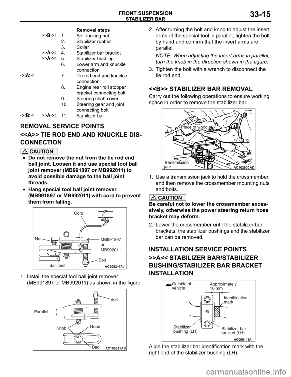
Removal steps
>>B<<1.Self-locking nut
2.Stabilizer rubber
3.Collar
>>A<<4.Stabilizer bar bracket
>>A<<5.Stabilizer bushing
6.Lower arm and knuckle
connection
<>7.Tie rod end and knuckle
connection
8.Engine rear roll stopper
bracket connecting bolt
9.Steering shaft cover
10.Steering gear and joint
connecting bolt
<>>>A<<11 .Stabilizer bar
STABILIZER BA R
FRONT SU SPENSION33-15
REMOVA L SER V ICE POINTS
<> TIE ROD END AND KNUCKLE DIS-
CONNECTION
CAUTION
•Do not remove the nut from the tie rod end
ball joint. Loosen it and use special tool ball
joint remover (MB991897 or MB992011) to
avoid possible damage to the ball joint
threads.
•
AC208247AJ
Cord
BoltMB991897
or
MB992011
Nut
Ball joint
Hang special tool ball joint remover
(MB991897 or MB992011) with cord to prevent
them from falling.
1. Install the special tool ball joint remover (MB991897 or MB992011) as shown in the figure.
AC106821
Knob
Parallel
Bolt
Good Bad
AB
2. After turning the bolt and knob to adjust the insert arms of the special tool in parallel, tighten the bolt
by hand and confirm that the insert arms are
parallel.
NOTE: When adjusting the insert arms in parallel,
turn the knob in the direction shown in the figure.
3. Tighten the bolt with a wrench to disconnect the tie rod end.
<> STABILIZER BAR REMOVAL
Carry out the following operations to ensure working
space in order to remove the stabilizer bar.
AC102600 AD
Piece of wood
Transmission
jack
1. Use a transmission jack to hold the crossmember,
and then remove the crossmember mounting nuts
and bolts.
CAUTION
Be careful not to lower the crossmember exces-
sively, otherwise the power steering return hose
bracket may deform.
2. Lower the crossmember until the stabilizer bar
brackets, the stabilizer bush ings and the stabilizer
bar can be removed.
INSTALLATION SERVICE POINTS
>>A<< STABILIZER BAR/STABILIZER
BUSHING/STABILIZ ER BAR BRACKET
INSTALLATION
AC006141 AI
Stabilizer bar
bracket (LH)
Outside of
vehicle
Stabilizer
bushing (LH) Approximately
10 mm
Identification
mark
Align the stabilizer bar iden
tification mark with the
right end of the stabilizer bushing (LH).
Page 199 of 800
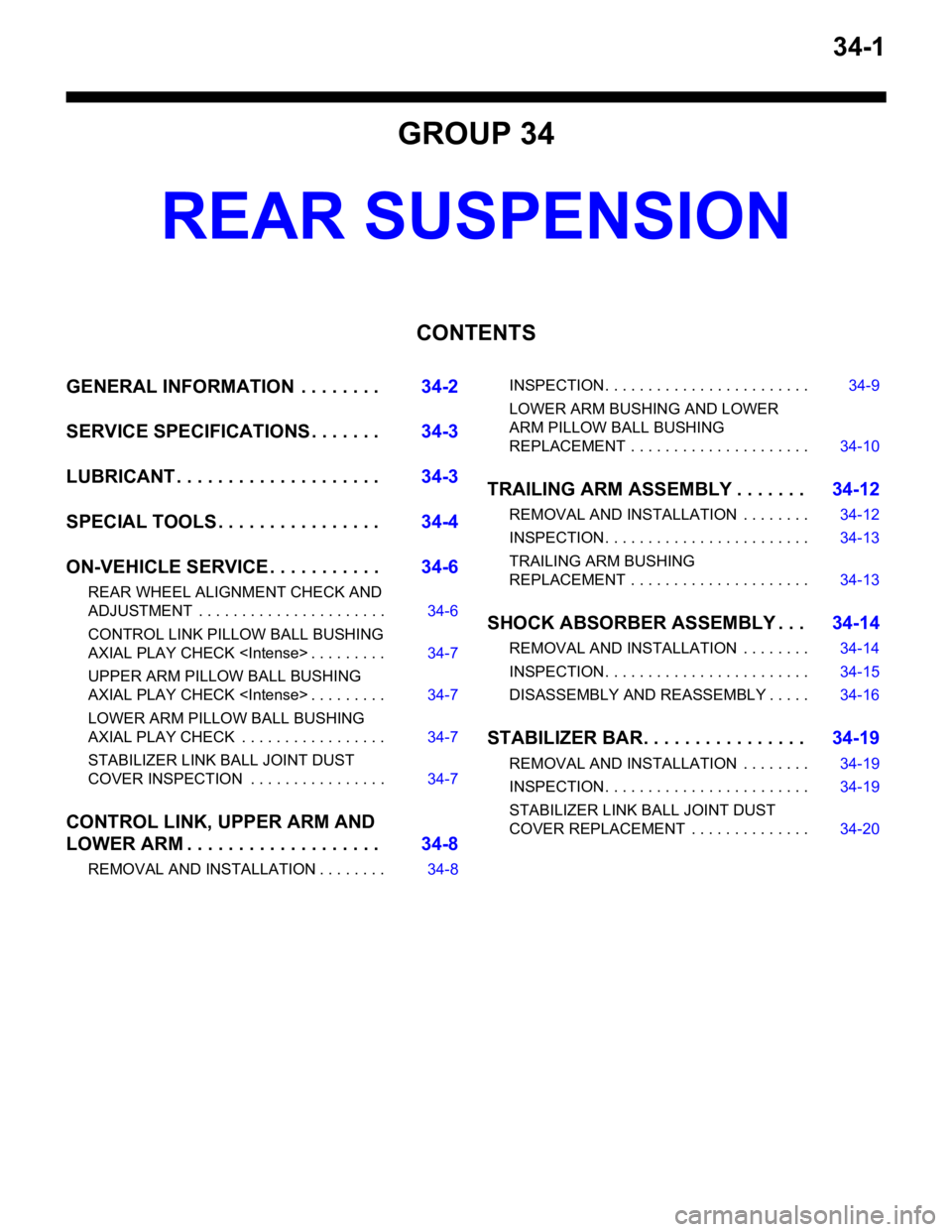
34-1
GROUP 34
REAR SUSPENSION
CONTENTS
GENERAL INFORMATION . . . . . . . .34-2
SERVICE SPECIFICATIONS . . . . . . .34-3
LUBRICANT . . . . . . . . . . . . . . . . . . . .34-3
SPECIAL TOOLS . . . . . . . . . . . . . . . .34-4
ON-VEHICLE SERVICE . . . . . . . . . . .34-6
REAR WHEEL ALIGNMENT CHECK AND
ADJUSTMENT . . . . . . . . . . . . . . . . . . . . . . 34-6
CONTROL LINK PILLOW BALL BUSHING
AXIAL PLAY CHECK
UPPER ARM PILLOW BALL BUSHING
AXIAL PLAY CHECK
LOWER ARM PILLOW BALL BUSHING
AXIAL PLAY CHECK . . . . . . . . . . . . . . . . . 34-7
STABILIZER LINK BALL JOINT DUST
COVER INSPECTION . . . . . . . . . . . . . . . . 34-7
CONTROL LINK, UPPER ARM AND
LOWER ARM . . . . . . . . . . . . . . . . . . .34-8
REMOVAL AND INSTALLATION . . . . . . . . 34-8
INSPECTION. . . . . . . . . . . . . . . . . . . . . . . . 34-9
LOWER ARM BUSHING AND LOWER
ARM PILLOW BALL BUSHING
REPLACEMENT . . . . . . . . . . . . . . . . . . . . . 34-10
TRAILING ARM ASSEMBLY . . . . . . .34-12
REMOVAL AND INSTALLATION . . . . . . . . 34-12
INSPECTION. . . . . . . . . . . . . . . . . . . . . . . . 34-13
TRAILING ARM BUSHING
REPLACEMENT . . . . . . . . . . . . . . . . . . . . . 34-13
SHOCK ABSORBER ASSEMBLY . . .34-14
REMOVAL AND INSTALLATION . . . . . . . . 34-14
INSPECTION. . . . . . . . . . . . . . . . . . . . . . . . 34-15
DISASSEMBLY AND REASSEMBLY . . . . . 34-16
STABILIZER BAR. . . . . . . . . . . . . . . .34-19
REMOVAL AND INSTALLATION . . . . . . . . 34-19
INSPECTION. . . . . . . . . . . . . . . . . . . . . . . . 34-19
STABILIZER LINK BALL JOINT DUST
COVER REPLACEMENT . . . . . . . . . . . . . . 34-20
Page 201 of 800
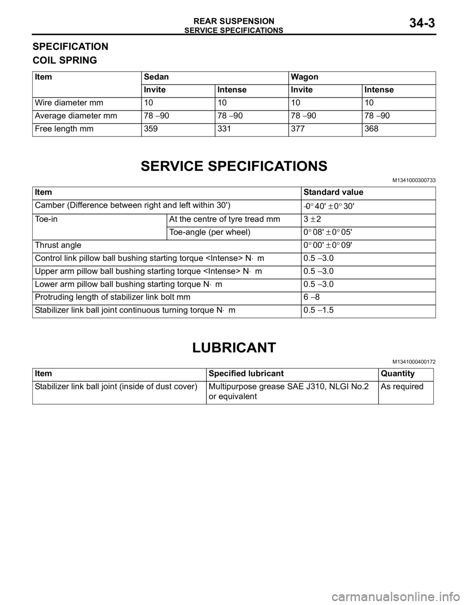
SERVICE SPECIFICATIONS
REAR SUSPENSION34-3
SPECIFICATION
COIL SPRING
ItemSedanWagon
InviteIntenseInviteIntense
Wire diameter mm10101010
Average diameter mm78 − 9078 − 9078 − 9078 − 90
Free length mm359331377368
SERVICE SPECIFICATIONS
M1341000300733
ItemStandard value
Camber (Difference between right and left within 30') −0°40' ± 0°30'
Toe-inAt the centre of tyre tread mm3 ± 2
Toe-angle (per wheel)0°08' ± 0°05'
Thrust angle0°00' ± 0°09'
Control link pillow ball bushing starting torque
Upper arm pillow ball bushing starting torque
Lower arm pillow ball bushing starting torque N⋅m0.5 − 3.0
Protruding length of stabilizer link bolt mm6 − 8
Stabilizer link ball joint continuous turning torque N⋅m0.5 − 1.5
LUBRICANT
M1341000400172
ItemSpecified lubricantQuantity
Stabilizer link ball joint (inside of dust cover)Multipurpose grease SAE J310, NLGI No.2
or equivalentAs required
Page 204 of 800
ON-VEHICLE SERVICE
REAR SUSPENSION34-6
ON-VEHICLE SERVICE
REAR WHEEL ALIGNMENT CHECK AND
ADJUSTMENT
M1341011000372
Measure wheel alignment with an alignment equip-
ment on level earth.
The rear suspension, wheels, and tyres should be
serviced to the normal condition prior to wheel align
-
ment measurement.
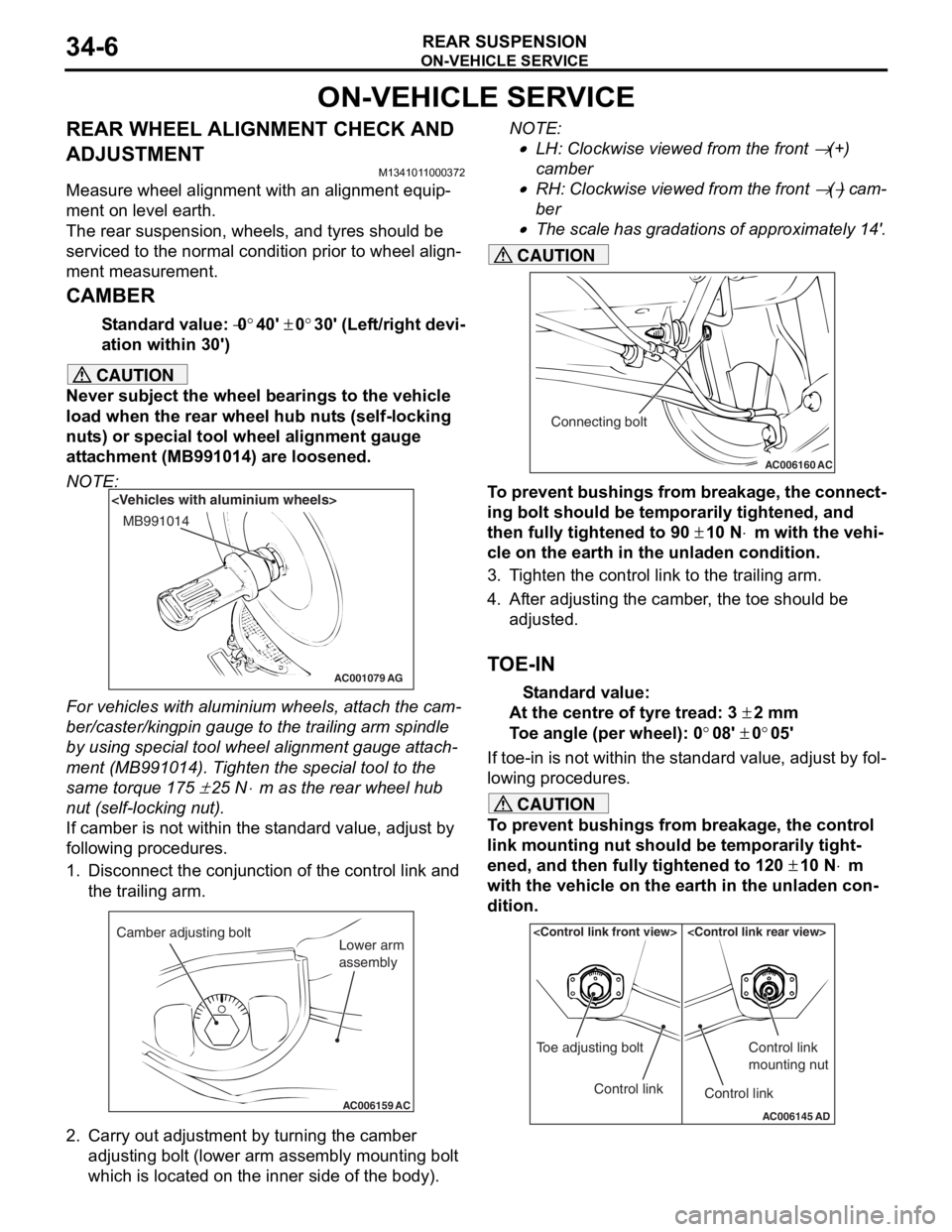
CAMBER
Standard value: −0°40' ± 0°30' (Left/right devi-
ation within 30')
CAUTION
Never subject the wheel bearings to the vehicle
load when the rear wheel hub nuts (self-locking
nuts) or special tool wheel alignment gauge
attachment (MB991014) are loosened.
NOTE:
AC001079
MB991014
AG
For vehicles with aluminium wheels, attach the cam-
ber/caster/kingpin gauge to the trailing arm spindle
by using special tool wheel alignment gauge attach
-
ment (MB991014). Tighten the special tool to the
same torque 175
± 25 N⋅m as the rear wheel hub
nut (self-locking nut).
If camber is not within the standard value, adjust by
following procedures.
1. Disconnect the conjunction of the control link and the trailing arm.
AC006159 AC
Camber adjusting bolt
Lower arm
assembly
2. Carry out adjustment by turning the camber
adjusting bolt (lower arm assembly mounting bolt
which is located on the inner side of the body).
NOTE: .
•LH: Clockwise viewed from the front → (+)
camber
•RH: Clockwise viewed from the front → (−) cam-
ber
•
AC006160 AC
Connecting bolt
The scale has gradations of approximately 14'.
CAUTION
To prevent bushings from breakage, the connect-
ing bolt should be temporarily tightened, and
then fully tightened to 90
± 10 N⋅m with the vehi-
cle on the earth in the unladen condition.
3. Tighten the control link to the trailing arm.
4. After adjusting the camber, the toe should be
adjusted.
TOE-IN
Standard value:
At the centre of tyre tread: 3 ± 2 mm
Toe angle (per wheel): 0°08' ± 0°05'
If toe-in is not within the standard value, adjust by fol-
lowing procedures.
CAUTION
To prevent bushings from breakage, the control
link mounting nut should be temporarily tight
-
ened, and then fully tightened to 120 ± 10 N⋅m
with the vehicle on the earth in the unladen con
-
dition.
AC006145 AD
Control link
Toe adjusting boltControl link
Control link
mounting nut
Page 205 of 800
ON-VEHICLE SERVICE
REAR SUSPENSION34-7
Carry out adjustment by turning the toe adjusting bolt
(control link mounting bolt which is located on the
inner side of the body).
NOTE: .
•LH: Clockwise viewed from the front → To e - i n
•RH: Clockwise viewed from the front → Toe-out
•Turning the toe adjusting bolt by one groove of
the scale, toe can be changed approximately 2.6
mm (single side toe angle equivalent to 16').
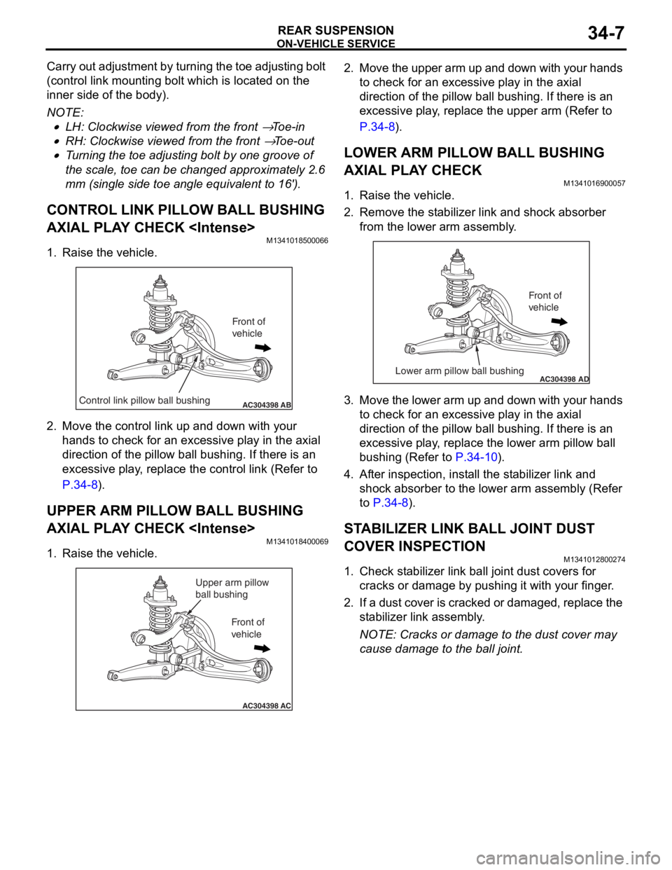
CONTROL LINK PILLOW BALL BUSHING
AXIAL PLAY CHECK
M1341018500066
1. Raise the vehicle.
AC304398ABControl link pillow ball bushing
Front of
vehicle
2.Move the control link up and d o wn with your
ha nds to ch eck for an excessive pla y in the a x ia l
direct ion o f the p illow ball bushing . If the r e is an
exce ssive play , re place the cont rol link (Re f er to
P.34-8).
UPPER ARM PILLOW BALL BUSHING
AXIAL PLAY CHECK
M13410184 0006 9
1.Raise th e ve hicle.
AC304398AC
Upper arm pillow
ball bushing
Front of
vehicle
2. Move the up per arm up and down with you r hand s
to che ck for an e xce ssive play in the axial
d i rection o f the p illow ball bushing . If the r e is an
e xce ssive play , re place the upper arm (Refe r to
P.34-8).
LOWER ARM PILLOW BALL BUSHING
AXIAL PLAY CHECK
M13410169 0005 7
1.Raise th e ve hicle.
2.Remove the st a b ilizer link and shock a b sorb er
f r om t h e l o we r arm a s s e mb l y .
AC304398ADLower arm pillow ball bushing
Front of
vehicle
3.Move the lower a r m u p and down with your h ands
to che ck for an e xce ssive play in the axial
d i rection o f the p illow ball bushing . If the r e is an
e xce ssive play , re place the lower a r m pillo w b a ll
b u shing (Refer to
P.34-10).
4.Af ter inspe c tio n , in st all the st a b ilizer link and
shock a b sorb er to the lower arm assembly (Refer
to
P.34-8).
STABILIZER LINK BALL JOINT DUST
COVER INSPECTION
M1341 0128 0027 4
1.Check st abilize r lin k ba ll joint dust covers f o r
cracks o r damage by pushing it wit h you r fing er .
2. If a du st cove r is crack ed or da mag ed, rep l ace t he
st a b ili zer link assembly .
NOTE: Cracks or dama ge to t he dust co ver may
cause damage to the b a ll join t.
Page 207 of 800
