MITSUBISHI LANCER EVOLUTION 2007 Service Owners Manual
Manufacturer: MITSUBISHI, Model Year: 2007, Model line: LANCER EVOLUTION, Model: MITSUBISHI LANCER EVOLUTION 2007Pages: 1449, PDF Size: 56.82 MB
Page 91 of 1449

HOW TO READ THE WIRING DIAGRAMS -How to Read Circuit DiagramsA-5
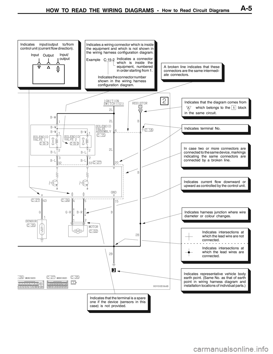
Indicates input/output to/from
control unit (current flow direction).
Input
OutputInput/
output
In case two or more connectors are
connected to the same device, markings
indicating the same connectors are
connected by a broken line.
Indicates current flow downward or
upward as controlled by the control unit.
Indicates harness junction where wire
diameter or colour changes.
Indicates intersections at
which the lead wire are not
connected.
Indicates intersections at
which the lead wires are
connected.
Indicates representative vehicle body
earth point. (Same No. as that of earth
point in wiring harness diagram and
installation locations of individual parts.)
Indicates that the terminal is a spare
one if the device (sensors in this
case) is not provided.
Indicates terminal No.
Indicates that the diagram comes from
Awhich belongs to the block
in the same circuit.1
A broken line indicates that these
connectors are the same intermedi-
ate connectors.
Indicates a wiring connector which is inside
the equipment and which is not shown in
the wiring harness configuration diagram.
Example C-15-2
Indicates the connector number
shown in the wiring harness
configuration diagram.Indicates a connector
which is inside the
equipment, numbered
in order starting from 1.
Page 92 of 1449

HOW TO READ THE WIRING DIAGRAMS -Markings for Connector EarthingA-6
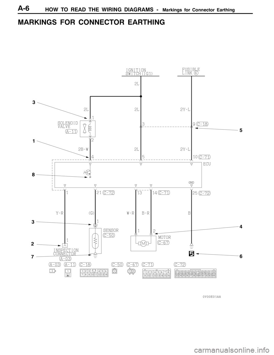
MARKINGS FOR CONNECTOR EARTHING
6
5
3
4
3
8
2
7
1
Page 93 of 1449

HOW TO READ THE WIRING DIAGRAMS -Markings for Connector EarthingA-7
ItemNo.Connector/EarthingSymbolContents
Connector
and terminal
marking1Male connectorMale terminalThe male and female terminals are
indicated as shown. The connector
with male terminal(s) is called as
male connector and indicated by
double connector contour linens,
while the connector with female
Male
terminalMale connector
whiletheconnectorwithfemale
terminal(s) is called as female
connector and indicated by single
connector contour line.
-
Female
connec-
tor
Female terminal
Female
terminal
Female connector
Connector
symbol
marking2DeviceThe symbol indicates the vehicle
connector as viewed from the
illustrated direction. At the connec-
tion with a device, the connector
symbol on the device side is
shown, and for an intermediate
connector, a male connector sym-
bolisshownForspareconnectors
Intermediate connector
bolisshown.For spare connectors
and check connectors, no device is
connected, and so the harness-
side connector symbol is shown for
these connectors. The details for
the diagnosis connector differ from
the above description. For details,
refer to the “MUT-II operation
instructions”.
Spare connector, check connector
instructions.
Page 94 of 1449

HOW TO READ THE WIRING DIAGRAMS -Markings for Connector EarthingA-8
ItemNo.Connector/EarthingSymbolContents
Connector
connection
marking3Direct connection typeA connection between a device
and connector on the harness side
is either by direct insertion in the
device (direct connection type) or
by connection with a harness
connector on the device side
furnished (harness connection
type)Thetwotypesareindicated
4Harness connection type
type).Thetwotypes areindicated
as illustrated.
5Intermediate connector
Earth
markings6Body earthEarth is either by body earth,
device earth or control unit interior
earth. These are indicated as
illustrated.
7Device earth
8Earth in control unit
Page 95 of 1449

HOW TO READ THE WIRING DIAGRAMS -Wire Colour CodesA-9
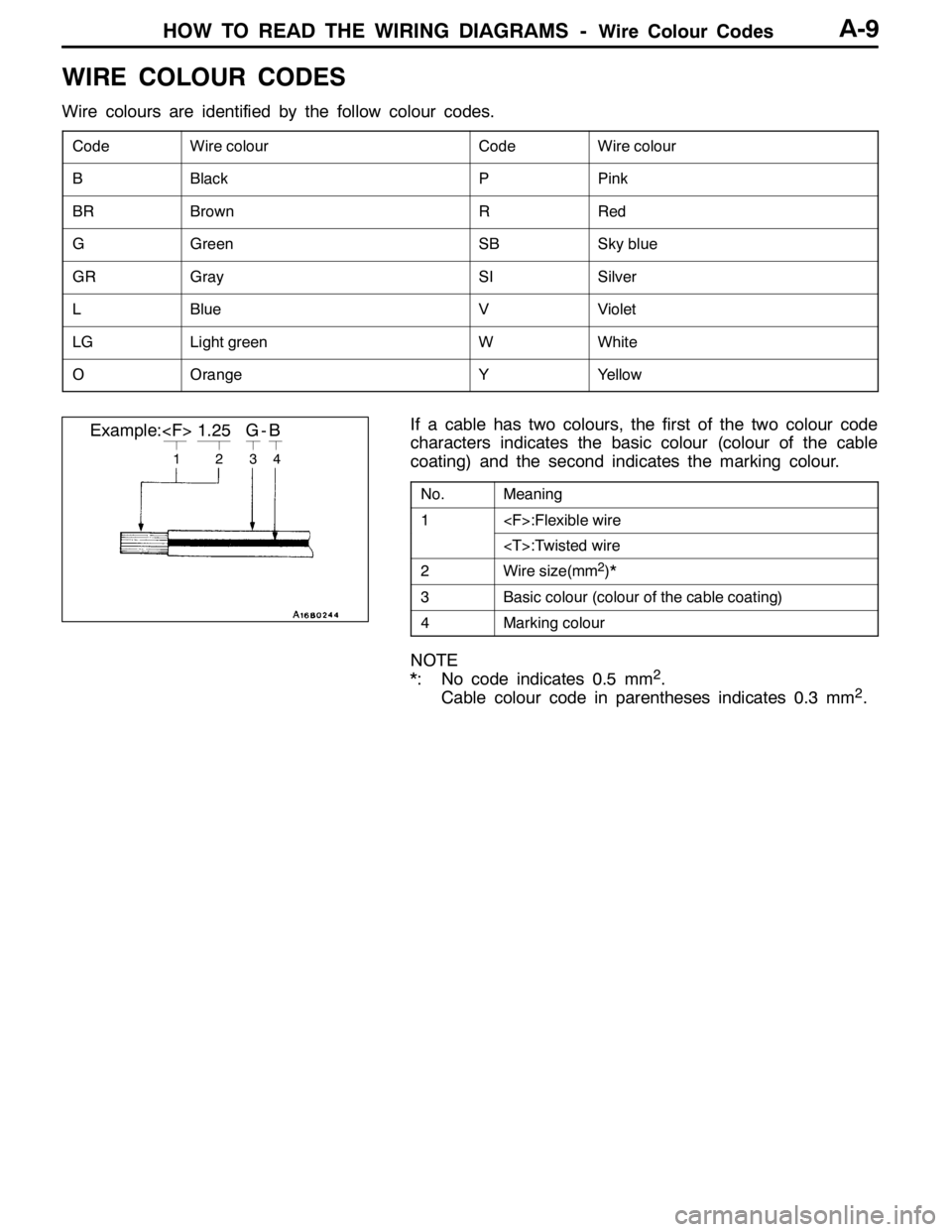
WIRE COLOUR CODES
Wire colours are identified by the follow colour codes.
CodeWire colourCodeWire colour
BBlackPPink
BRBrownRRed
GGreenSBSky blue
GRGraySISilver
LBlueVViolet
LGLight greenWWhite
OOrangeYYellow
If a cable has two colours, the first of the two colour code
characters indicates the basic colour (colour of the cable
coating) and the second indicates the marking colour.
No.Meaning
1
2Wire size(mm2)*
3Basic colour (colour of the cable coating)
4Marking colour
NOTE
*: No code indicates 0.5 mm2.
Cable colour code in parentheses indicates 0.3 mm2.
1234
Example:
Page 96 of 1449

HOW TO READ THE WIRING DIAGRAMS -Abbreviation SymbolsA-10
ABBREVIATION SYMBOLS
The abbreviation symbols used in wiring diagrams are defined below.
1. Abbreviation symbols used for system name
Abbreviation
symbolsMeaningAbbreviation
symbolsMeaning
A/CAir conditionerEGRExhaust gas recirculation
ABSAnti-skid braking systemETACSElectronic time alarm control system
ACDActive center differentialSRSSupplemental restraint system
AY CActive yaw control
2. Abbreviation symbols used for combination meters
Abbreviation
symbolsMeaningAbbreviation
symbolsMeaning
ABSAnti-skid braking system warning lampSNOWActive center differential mode indicator
lamp
BEAMHigh beam indicator lampSPEEDSpeedmeter
BRAKEBrake warning lampSRSSupplemental restraint system warning
lamp
CHECK
ENGINECheck engine warning lampTARMACActive center differential mode indicator
lamp
CHGCharging warning lampT/GAEngine coolant temperature gauge
DOORDoor-ajar warning lampTACHOTachometer
F/GAFuel gaugeTAILTail, position and licence plate indicator
lamp
FRONT FOGFront fog indicator lamp
lamp
FUELLow fuel warning lampTRIPTripmeter
GRAVELActive center differential mode indicator
lampTURN (LH)Turn signal indicator lamp (LH)
ODOOdometerTURN (RH)Trun signal indicator lamp (RH)
OILOil pressure warning lampWATER
SPRAY
Intercooler water spray indicator lamp
REAR FOGRear fog indicator lamp
SPRAY
3. Abbreviation symbols used for switched and relay
Name of switches and
relaysAbbreviation
symbolsOperation
Blower switchLOBlower operates at low speed
MLBlower operates at medium low speed
MHBlower operates at medium high speed
HIBlower operates at high speed
Page 97 of 1449

HOW TO READ THE WIRING DIAGRAMS -Abbreviation SymbolsHOW TO READ THE WIRING DIAGRAMS -Abbreviation SymbolsA-11
Name of switches and
relaysOperation Abbreviation
symbols
Dimmer passing
switch
LOLow beams ON
switch
HIHigh beams ON
PASS
Door lock actuatorLOCKDoor lock
UNLOCKDoor unlock
Headlamp leveling
switch
1Low beam light axis drops by one step
switch
2Low beam light axis drops by two step
3Low beam light axis drops by three step
4Low beam light axis drops by four step
Ignition switchACCWhen turned to the ACC (ACCESSORY) or ON position, the power
circuit will start
IG1Even when at the ST (START) position, the power circuit will start
IG2When at the ST (START) position, the power circuit will not start
functioning
Intercooler water spray
switch
MANUALWater is sprayed while the switch is being pressed
switch
AUTOWater is sprayed automatically according to driving conditions
Lighting switchTAILPosition, tail, licence plate and illumination lamps ON
HEADHeadlamps ON
OthersOFFSwitched OFF
ONSwitched ON
Power window switchUPWindow closes
DOWNWindow opens
AUTO UPWindow is easily closed with one action
AUTO DOWNWindow is easily opened with one action
LOCKPrevents all switches other than the main switch from operating the
power windows
Remote controlled
mirrorswitch
LHL.H. mirror operates
mirror switch
RHR.H. mirror operates
Room lamp switchDOORRoom lamp ON when a door is open
Turn signal switchLHL.H. signal lamps ON
RHR.H. signal lamps ON
Page 98 of 1449

HOW TO READ THE WIRING DIAGRAMS -Abbreviation SymbolsA-12
Name of switches and
relaysOperation Abbreviation
symbols
Windshield wiper
switch
MISTWiper operates once
switch
INTWiper operates intermittently
LOWiper operates at low speed
HIWiper operates at high speed
4. Other abbreviation symbols
Abbreviation
symbolsMeaningAbbreviation
symbolsMeaning
ECUElectronic control unitLCDLiquid crystal display
GNDEarthLHLeft hand
ILLIllumination lampLHDL.H. drive vehicles
INDIndicator lampRHRight hand
J/BJunction blockRHDR.H. drive vehicles
J/CJoint connector
Page 99 of 1449

B-1
ELECTRICAL
WIRING
CONTENTS
WIRING HARNESS CONFIGURATION
DIAGRAMS 4.........................
OVERALL WIRING DIAGRAM
L.H. drive vehicles 4........................
R.H. drive vehicles 5........................
ENGINE COMPARTMENT
L.H. drive vehicles 6........................
R.H. drive vehicles 8........................
ENGINE AND TRANSMISSION
L.H. drive vehicles 10.......................
R.H. drive vehicles 14.......................
DASH PANEL
L.H. drive vehicles 18.......................
R.H. drive vehicles 24.......................
FLOOR AND ROOF
L.H. drive vehicles 30.......................
R.H. drive vehicles 32.......................
DOOR
L.H. drive vehicles 34.......................
R.H. drive vehicles 36.......................
LUGGAGE COMPARTMENT
L.H. drive vehicles 38.......................
R.H. drive vehicles 39.......................
SINGLE PART INSTALLATION
POSITION 40.........................
RELAY 40.................................
ECU 41...................................
SENSOR 43...............................
SOLENOID VALVE 46......................
INSPECTION CONNECTOR AND SPARE
CONNECTOR 47...........................
FUSIBLE LINK AND FUSE 48..............
EARTH CABLE 49.........................
EARTH 50.................................
CIRCUIT DIAGRAMS 54...............
J/B 54....................................
J/C
L.H. drive vehicles 56.......................
R.H. drive vehicles 62.......................
CENTRALIZED JUNCTION 68..............
POWER DISTRIBUTION SYSTEM 74........
STARTING SYSTEM 79....................
Page 100 of 1449

B-2
S
PWGEE
IGNITION SYSTEM
L.H. drive vehicles 82.......................
R.H. drive vehicles 83.......................
CHARGING SYSTEM 84...................
ENGINE CONTROL SYSTEM
L.H. drive vehicles 86.......................
R.H. drive vehicles 94.......................
COOLING SYSTEM 102...................
HEADLAMP
L.H. drive vehicles 103......................
R.H. drive vehicles 106......................
TAIL LAMP, POSITION LAMP, LICENCE
PLATE LAMP AND LIGHTING MONITOR
BUZZER
L.H. drive vehicles 110......................
R.H. drive vehicles 114......................
ROOM LAMP AND LUGGAGE
COMPARTMENT LAMP
L.H. drive vehicles 118......................
R.H. drive vehicles 121......................
REAR FOG LAMP
L.H. drive vehicles 124......................
R.H. drive vehicles 127......................
HEADLAMP LEVELING SYSTEM
L.H. drive vehicles 130......................
R.H. drive vehicles 132......................
TURN-SIGNAL LAMP AND HAZARD
WARNING LAMP
L.H. drive vehicles 134......................
R.H. drive vehicles 138......................
BACK-UP LAMP
L.H. drive vehicles 142......................
R.H. drive vehicles 143......................
STOP LAMP
L.H. drive vehicles 144......................
R.H. drive vehicles 145......................
HORN 146................................
METER AND GAUGE
L.H. drive vehicles 148......................
R.H. drive vehicles 152......................
FUEL WARNING LAMP 156...............
OIL PRESSURE WARNING LAMP 157.....
BRAKE WARNING LAMP 157.............
POWER WINDOWS
L.H. drive vehicles 158......................
R.H. drive vehicles 164......................
CENTRAL DOOR LOCKING SYSTEM
L.H. drive vehicles 170......................
R.H. drive vehicles 172......................
HEATER AND MANUAL AIR CONDITIONER
L.H. drive vehicles 174......................
R.H. drive vehicles 180......................
DEFOGGER 185..........................
WINDSHIELD WIPER AND WASHER
L.H. drive vehicles 186......................
R.H. drive vehicles 189......................
REMOTE CONTROLLED MIRROR
L.H. drive vehicles 192......................
R.H. drive vehicles 193......................
CLOCK 194..............................
CIGARETTE LIGHTER AND ASHTRAY
ILLUMINATION LAMP 195.................
AUDIO SYSTEM 196......................