MITSUBISHI LANCER EVOLUTION 2007 Service Repair Manual
LANCER EVOLUTION 2007
MITSUBISHI
MITSUBISHI
https://www.carmanualsonline.info/img/19/57084/w960_57084-0.png
MITSUBISHI LANCER EVOLUTION 2007 Service Repair Manual
Trending: check oil, battery replacement, torque, battery location, fuel, tire pressure, coolant level
Page 111 of 1449
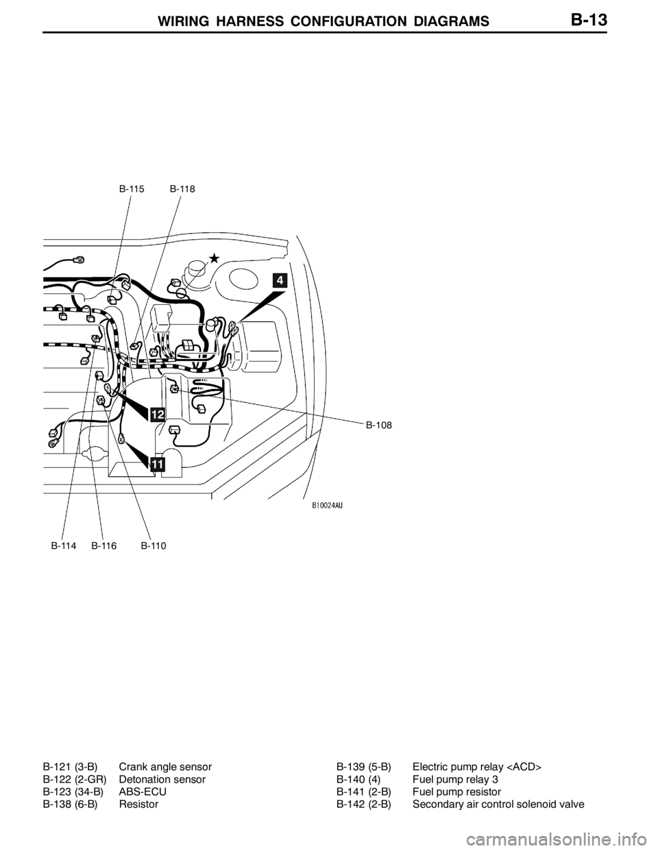
WIRING HARNESS CONFIGURATION DIAGRAMS
B-115
B-114
B-118
B-108
B-116B-110
4
11
12
B-13
B-121 (3-B) Crank angle sensor
B-122 (2-GR) Detonation sensor
B-123 (34-B) ABS-ECU
B-138 (6-B) ResistorB-139 (5-B) Electric pump relay
B-140 (4) Fuel pump relay 3
B-141 (2-B) Fuel pump resistor
B-142 (2-B) Secondary air control solenoid valve
Page 112 of 1449
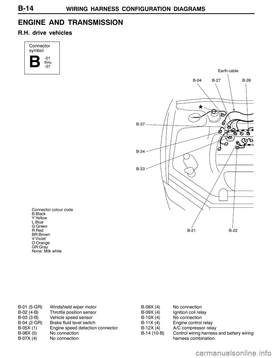
WIRING HARNESS CONFIGURATION DIAGRAMS
Connector
symbol
-01
thru
-37
B
Earth cable
B-27B-26B-04
B-22B-21
B-37
B-34
B-23
Connector colour code
B:Black
Y:Yellow
L:Blue
G:Green
R:Red
BR:Brown
V:Violet
O:Orange
GR:Gray
None: Milk white
B-14
ENGINE AND TRANSMISSION
R.H. drive vehicles
B-01 (5-GR) Windshield wiper motor
B-02 (4-B) Throttle position sensor
B-03 (3-B) Vehicle speed sensor
B-04 (2-GR) Brake fluid level switch
B-05X (1) Engine speed detection connector
B-06X (5) No connection
B-07X (4) No connectionB-08X (4) No connection
B-09X (4) Ignition coil relay
B-10X (4) No connection
B-11X (4) Engine control relay
B-12X (4) A/C compressor relay
B-14 (10-B) Control wiring harness and battery wiring
harness combination
Page 113 of 1449
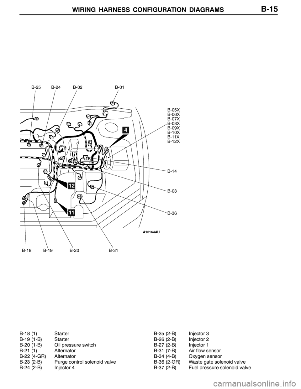
WIRING HARNESS CONFIGURATION DIAGRAMS
B-25
B-18
B-24B-02B-01
B-05X
B-06X
B-07X
B-08X
B-09X
B-10X
B-11X
B-12X
B-14
B-03
B-36
B-19B-20B-31
4
11
12
B-15
B-18 (1) Starter
B-19 (1-B) Starter
B-20 (1-B) Oil pressure switch
B-21 (1) Alternator
B-22 (4-GR) Alternator
B-23 (2-B) Purge control solenoid valve
B-24 (2-B) Injector 4B-25 (2-B) Injector 3
B-26 (2-B) Injector 2
B-27 (2-B) Injector 1
B-31 (7-B) Air flow sensor
B-34 (4-B) Oxygen sensor
B-36 (2-GR) Waste gate solenoid valve
B-37 (2-B) Fuel pressure solenoid valve
Page 114 of 1449
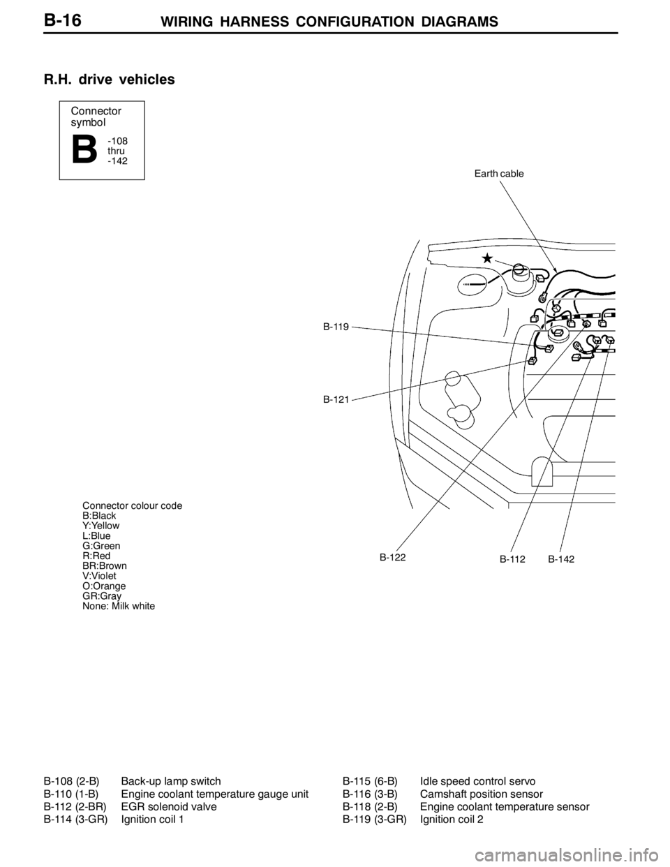
WIRING HARNESS CONFIGURATION DIAGRAMS
Connector
symbol
-108
thru
-142
B
Earth cable
B-119
B-121
B-112B-122B-142
Connector colour code
B:Black
Y:Yellow
L:Blue
G:Green
R:Red
BR:Brown
V:Violet
O:Orange
GR:Gray
None: Milk white
B-16
R.H. drive vehicles
B-108 (2-B) Back-up lamp switch
B-110 (1-B) Engine coolant temperature gauge unit
B-112 (2-BR) EGR solenoid valve
B-114 (3-GR) Ignition coil 1B-115 (6-B) Idle speed control servo
B-116 (3-B) Camshaft position sensor
B-118 (2-B) Engine coolant temperature sensor
B-119 (3-GR) Ignition coil 2
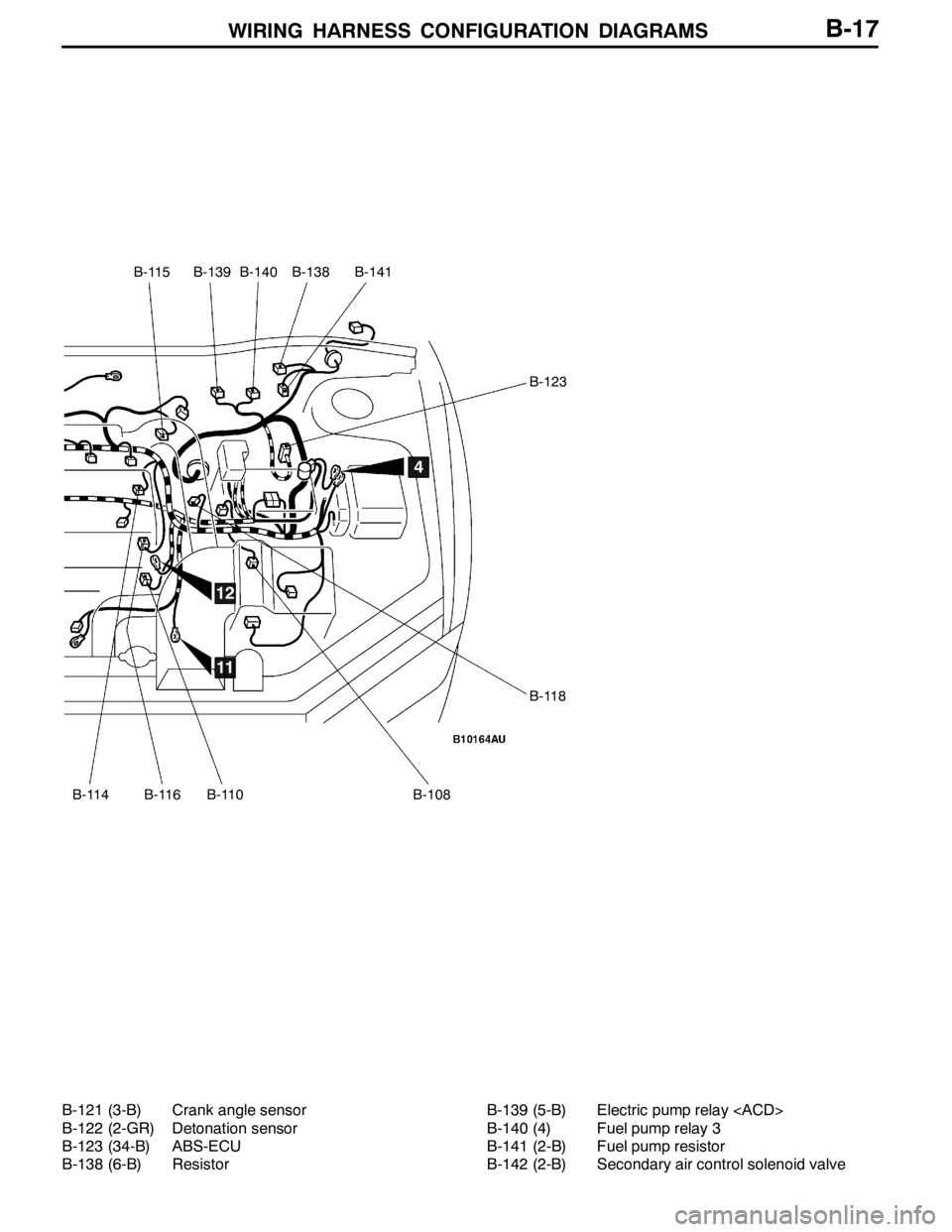
Page 115 of 1449
WIRING HARNESS CONFIGURATION DIAGRAMS
B-115
B-114B-116B-110B-108
B-123
B-118
B-139B-140B-138B-141
4
11
12
B-17
B-121 (3-B) Crank angle sensor
B-122 (2-GR) Detonation sensor
B-123 (34-B) ABS-ECU
B-138 (6-B) ResistorB-139 (5-B) Electric pump relay
B-140 (4) Fuel pump relay 3
B-141 (2-B) Fuel pump resistor
B-142 (2-B) Secondary air control solenoid valve
Page 116 of 1449
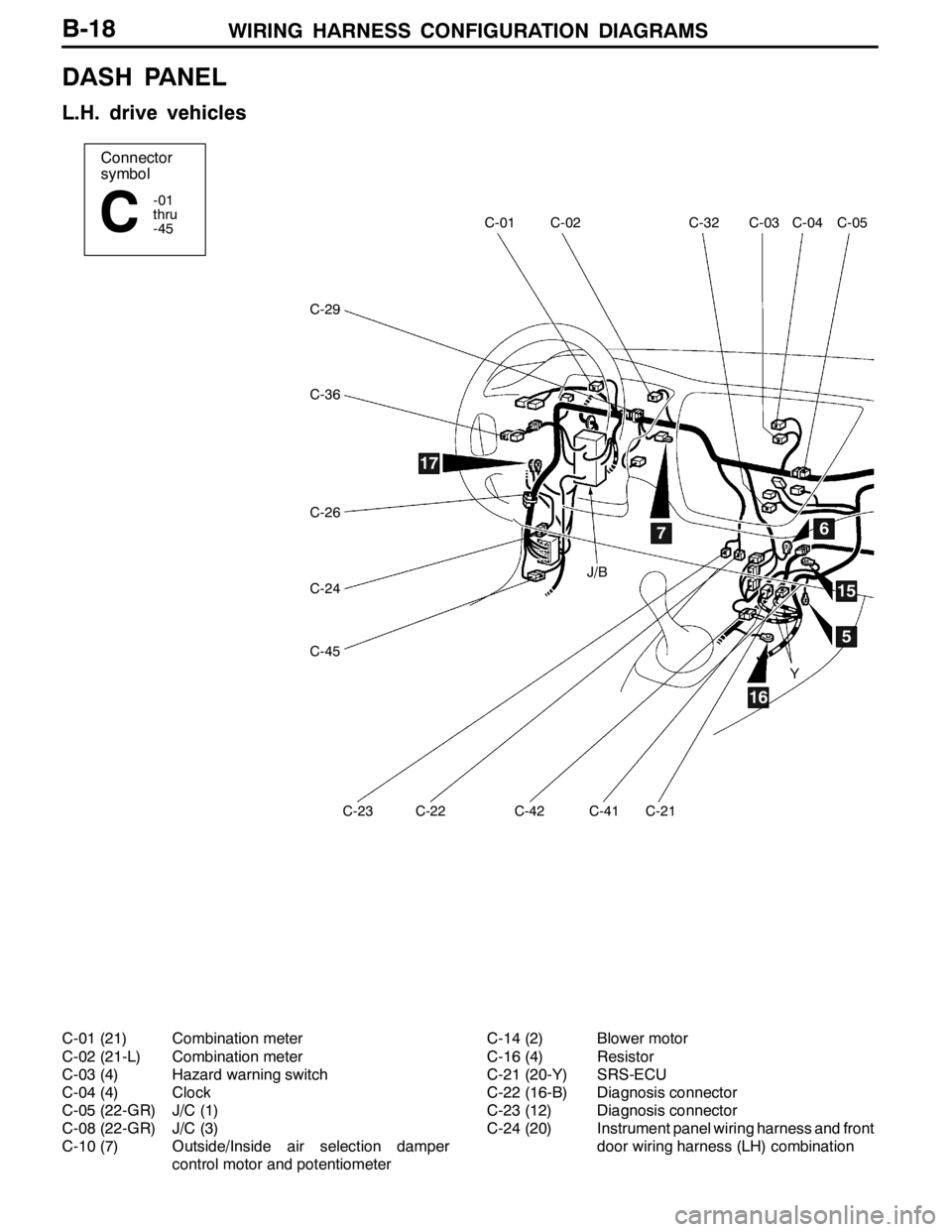
WIRING HARNESS CONFIGURATION DIAGRAMS
Connector
symbol
-01
thru
-45
C
C-29
C-05C-04C-03C-32C-02C-01
C-36
C-26
C-24
C-45
C-23C-22C-42C-41C-21
67
5
16
17
15
J/B
Y
B-18
DASH PANEL
L.H. drive vehicles
C-01 (21) Combination meter
C-02 (21-L) Combination meter
C-03 (4) Hazard warning switch
C-04 (4) Clock
C-05 (22-GR) J/C (1)
C-08 (22-GR) J/C (3)
C-10 (7) Outside/Inside air selection damper
control motor and potentiometerC-14 (2) Blower motor
C-16 (4) Resistor
C-21 (20-Y) SRS-ECU
C-22 (16-B) Diagnosis connector
C-23 (12) Diagnosis connector
C-24 (20) Instrument panel wiring harness and front
door wiring harness (LH) combination
Page 117 of 1449
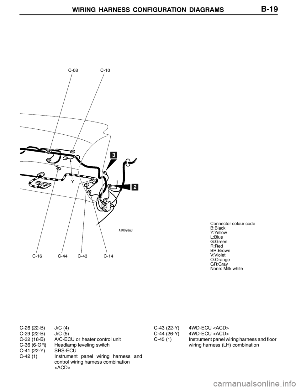
WIRING HARNESS CONFIGURATION DIAGRAMS
C-08
C-16
C-10
C-14
2
3
Y
Connector colour code
B:Black
Y:Yellow
L:Blue
G:Green
R:Red
BR:Brown
V:Violet
O:Orange
GR:Gray
None: Milk white
C-44C-43
B-19
C-26 (22-B) J/C (4)
C-29 (22-B) J/C (5)
C-32 (16-B) A/C-ECU or heater control unit
C-36 (6-GR) Headlamp leveling switch
C-41 (22-Y) SRS-ECU
C-42 (1) Instrument panel wiring harness and
control wiring harness combination
C-43 (22-Y) 4WD-ECU
C-44 (26-Y) 4WD-ECU
C-45 (1) Instrument panel wiring harness and floor
wiring harness (LH) combination
Page 118 of 1449
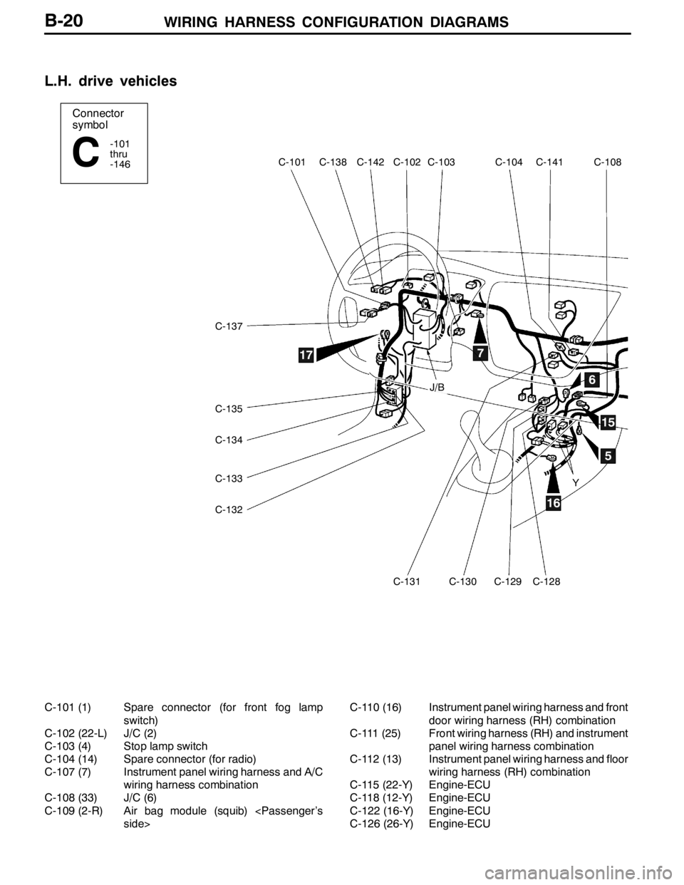
WIRING HARNESS CONFIGURATION DIAGRAMS
Connector
symbol
-101
thru
-146
C
C-137
C-135
C-134
C-133
C-132
C-131C-130C-129C-128
C-141C-104C-103C-102C-142C-138C-101C-108
5
6
7
15
16
17
J/B
Y
B-20
L.H. drive vehicles
C-101 (1) Spare connector (for front fog lamp
switch)
C-102 (22-L) J/C (2)
C-103 (4) Stop lamp switch
C-104 (14) Spare connector (for radio)
C-107 (7) Instrument panel wiring harness and A/C
wiring harness combination
C-108 (33) J/C (6)
C-109 (2-R) Air bag module (squib)
side>C-110 (16) Instrument panel wiring harness and front
door wiring harness (RH) combination
C-111 (25) Front wiring harness (RH) and instrument
panel wiring harness combination
C-112 (13) Instrument panel wiring harness and floor
wiring harness (RH) combination
C-115 (22-Y) Engine-ECU
C-118 (12-Y) Engine-ECU
C-122 (16-Y) Engine-ECU
C-126 (26-Y) Engine-ECU
Page 119 of 1449
WIRING HARNESS CONFIGURATION DIAGRAMS
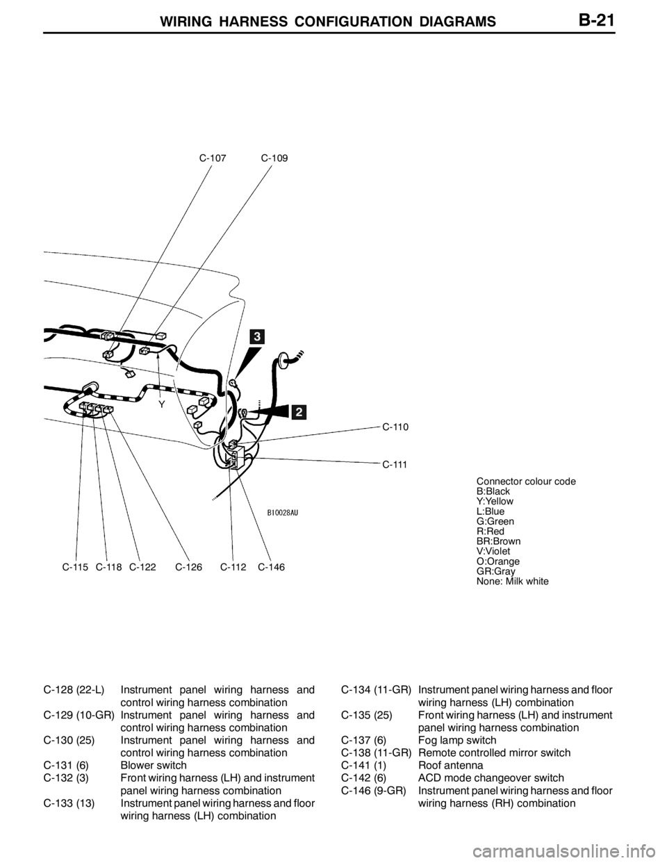
C-115
C-107C-109
C-110
C-111
C-118C-122C-126C-112C-146
2
3
Y
Connector colour code
B:Black
Y:Yellow
L:Blue
G:Green
R:Red
BR:Brown
V:Violet
O:Orange
GR:Gray
None: Milk white
B-21
C-128 (22-L) Instrument panel wiring harness and
control wiring harness combination
C-129 (10-GR) Instrument panel wiring harness and
control wiring harness combination
C-130 (25) Instrument panel wiring harness and
control wiring harness combination
C-131 (6) Blower switch
C-132 (3) Front wiring harness (LH) and instrument
panel wiring harness combination
C-133 (13) Instrument panel wiring harness and floor
wiring harness (LH) combinationC-134 (11-GR) Instrument panel wiring harness and floor
wiring harness (LH) combination
C-135 (25) Front wiring harness (LH) and instrument
panel wiring harness combination
C-137 (6) Fog lamp switch
C-138 (11-GR) Remote controlled mirror switch
C-141 (1) Roof antenna
C-142 (6) ACD mode changeover switch
C-146 (9-GR) Instrument panel wiring harness and floor
wiring harness (RH) combination
Page 120 of 1449
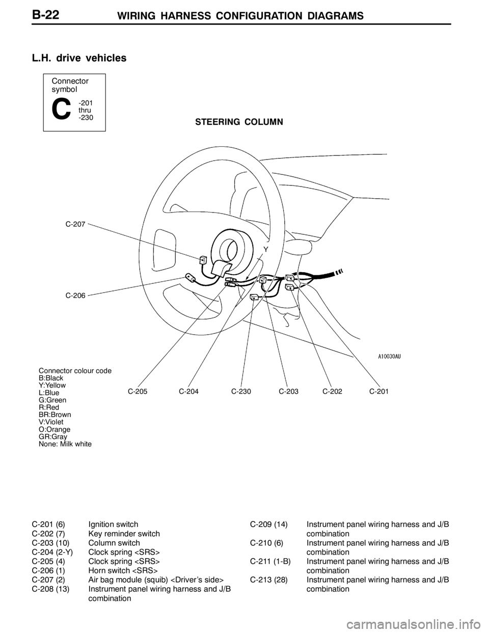
WIRING HARNESS CONFIGURATION DIAGRAMS
Connector
symbol
-201
thru
-230
CSTEERING COLUMN
C-207
C-206
C-205C-204C-230C-203C-202C-201 Y
Connector colour code
B:Black
Y:Yellow
L:Blue
G:Green
R:Red
BR:Brown
V:Violet
O:Orange
GR:Gray
None: Milk white
B-22
L.H. drive vehicles
C-201 (6) Ignition switch
C-202 (7) Key reminder switch
C-203 (10) Column switch
C-204 (2-Y) Clock spring
C-205 (4) Clock spring
C-206 (1) Horn switch
C-207 (2) Air bag module (squib)
C-208 (13) Instrument panel wiring harness and J/B
combinationC-209 (14) Instrument panel wiring harness and J/B
combination
C-210 (6) Instrument panel wiring harness and J/B
combination
C-211 (1-B) Instrument panel wiring harness and J/B
combination
C-213 (28) Instrument panel wiring harness and J/B
combination
Trending: ESP inoperative, hood release, fuel filter, fuses, transmission oil, rims, seats
