MITSUBISHI LANCER EVOLUTION 2007 Service Repair Manual
Manufacturer: MITSUBISHI, Model Year: 2007, Model line: LANCER EVOLUTION, Model: MITSUBISHI LANCER EVOLUTION 2007Pages: 1449, PDF Size: 56.82 MB
Page 1051 of 1449
BASIC BRAKE SYSTEM -On-vehicle Service35A-9
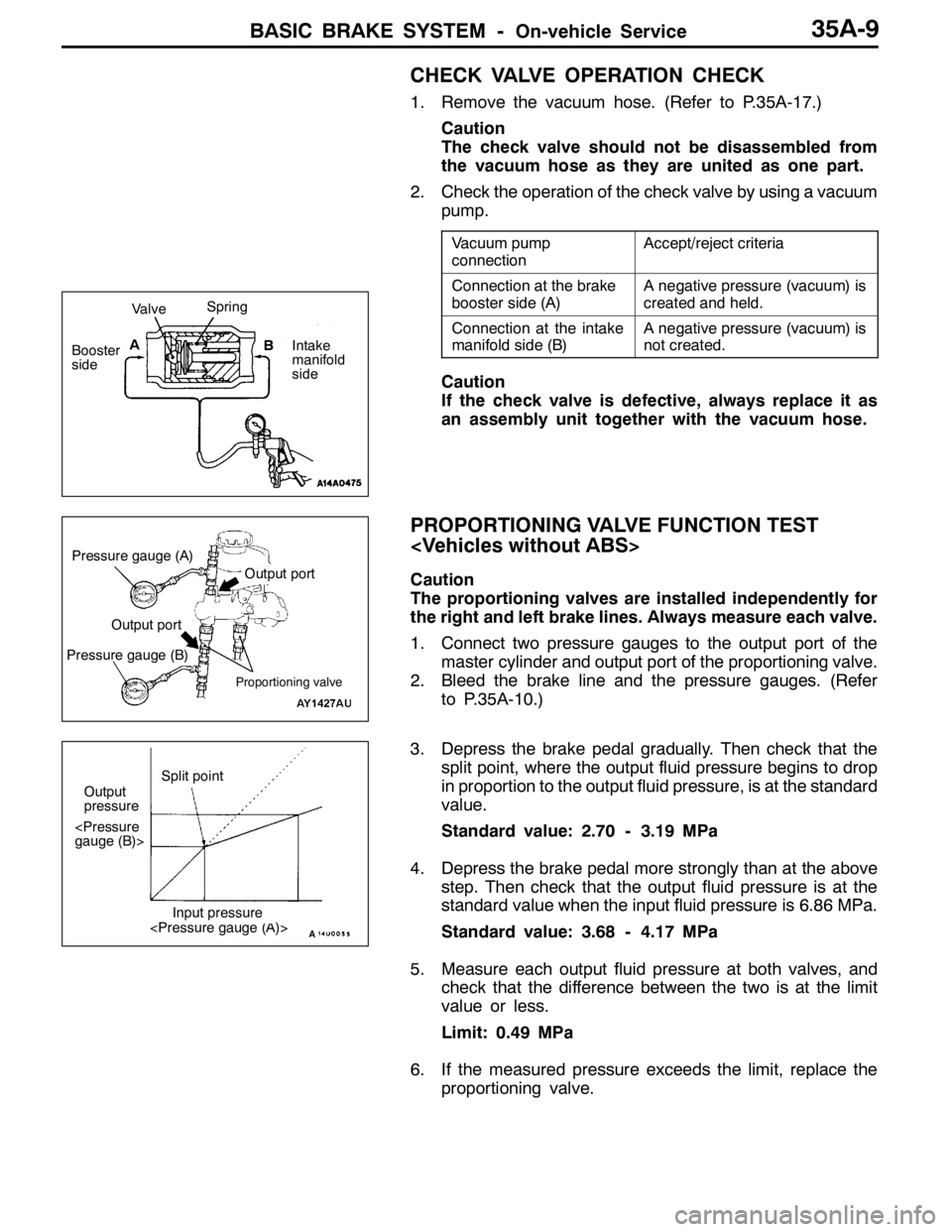
CHECK VALVE OPERATION CHECK
1. Remove the vacuum hose. (Refer to P.35A-17.)
Caution
The check valve should not be disassembled from
the vacuum hose as they are united as one part.
2. Check the operation of the check valve by using a vacuum
pump.
Vacuum pump
connectionAccept/reject criteria
Connection at the brake
booster side (A)A negative pressure (vacuum) is
created and held.
Connection at the intake
manifold side (B)A negative pressure (vacuum) is
not created.
Caution
If the check valve is defective, always replace it as
an assembly unit together with the vacuum hose.
PROPORTIONING VALVE FUNCTION TEST
Caution
The proportioning valves are installed independently for
the right and left brake lines. Always measure each valve.
1. Connect two pressure gauges to the output port of the
master cylinder and output port of the proportioning valve.
2. Bleed the brake line and the pressure gauges. (Refer
to P.35A-10.)
3. Depress the brake pedal gradually. Then check that the
split point, where the output fluid pressure begins to drop
in proportion to the output fluid pressure, is at the standard
value.
Standard value: 2.70 - 3.19 MPa
4. Depress the brake pedal more strongly than at the above
step. Then check that the output fluid pressure is at the
standard value when the input fluid pressure is 6.86 MPa.
Standard value: 3.68 - 4.17 MPa
5. Measure each output fluid pressure at both valves, and
check that the difference between the two is at the limit
value or less.
Limit: 0.49 MPa
6. If the measured pressure exceeds the limit, replace the
proportioning valve.
ValveSpring
Booster
sideA
B
Intake
manifold
side
Pressure gauge (A)
Proportioning valve
Output port
Output port
Pressure gauge (B)
Output
pressureSplit point
Page 1052 of 1449

BASIC BRAKE SYSTEM -On-vehicle Service35A-10
BLEEDING
Caution
Specified brake fluid: DOT3 or DOT4
Always use the specified brake fluid. Avoid using a
mixture of the specified brake fluid and other fluid.
MASTER CYLINDER BLEEDING
The master cylinder used has no check valve, so if bleeding
is carried out by the following procedure, bleeding of air from
the brake pipeline will become easier. (When brake fluid is
not contained in the master cylinder.)
1. Fill the reserve tank with brake fluid.
2. Keep the brake pedal depressed.
3. Have another person cover the master cylinder outlet
with a finger.
4. With the outlet still closed, release the brake pedal.
5. Repeat steps 2 - 4 three or four times to fill the inside
of the master cylinder with brake fluid.
BREMBO DISC BRAKE BLEEDING
Caution
Take care not to contact the parts or tools to the caliper
because the paint of caliper will be scratched. And if
there is brake fluid on the caliper, wipe out quickly.
Connect a vinyl tube to the outer end of the air bleeder screw
to bleed the circuit of air. Then, connect the vinyl tube to
the inner end and bleed the circuit of air. Except for these,
the conventional procedures shall be followed. After the circuit
has been bled of air, tighten both air bleeder screws securely.
BRAKE PIPE LINE BLEEDING
Bleed the air in the sequence shown in the figure.
Air bleeder screw
( ): R.H. drive vehicles
4 (2)
1 (3)
2 (4)
3 (1)
( ): R.H. drive vehicles
4, 6 (1, 3)
2 (5)
1, 3 (4, 6)
5 (2)
Vehicles with ABS
Vehicles without ABS
Page 1053 of 1449

BASIC BRAKE SYSTEM -On-vehicle Service35A-11
BRAKE FLUID LEVEL SENSOR CHECK
The brake fluid level sensor is in good condition if there is
no continuity when the float surface is above “MIN” and if
there is continuity when the float surface is below “MIN”.
DISC BRAKE PAD CHECK AND REPLACEMENT
NOTE
The wear indicator contacts the brake disc when the brake
pad thickness reaches approximately 2 mm and emit a
squealing sound to warn the driver.
1. Check the brake pad thickness through the caliper body
check port.
Standard value: 10.0 mm
Limit: 2.0 mm
2. When the thickness is less than the limit, always replace
the pads at an axle set.
3. Remove the pin bolt. Pivot the caliper assembly and hold
it with wires.
Caution
Do not wipe off the special grease that is on the pin
or allow it to contaminate the pin.
4. Remove the following parts from the caliper support.
1. Pad and wear indicator assembly
2. Pad assembly
3. Clip
4. Outer shim
5. In order to measure the brake drag force after pad
installation, measure the rotary-sliding resistance of the
hub with the pads removed. (Refer to P.35A-21.)
6. Install the pads and caliper assembly, and then check
the brake drag force. (Refer to P.35A-21.)
14Z0017
Front Rear
Front Rear
Front Rear
12 34
3
1
2 3
4
3
Page 1054 of 1449
BASIC BRAKE SYSTEM -On-vehicle Service35A-12
Caution
Take care not to contact the parts or tools to the caliper
because the paint of caliper will be scratched. And if
there is brake fluid on the caliper, wipe out quickly.
NOTE
The wear indicator contacts the brake disc when the brake
pad thickness reaches approximately 2 mm and emit a
squealing sound to warn the driver.
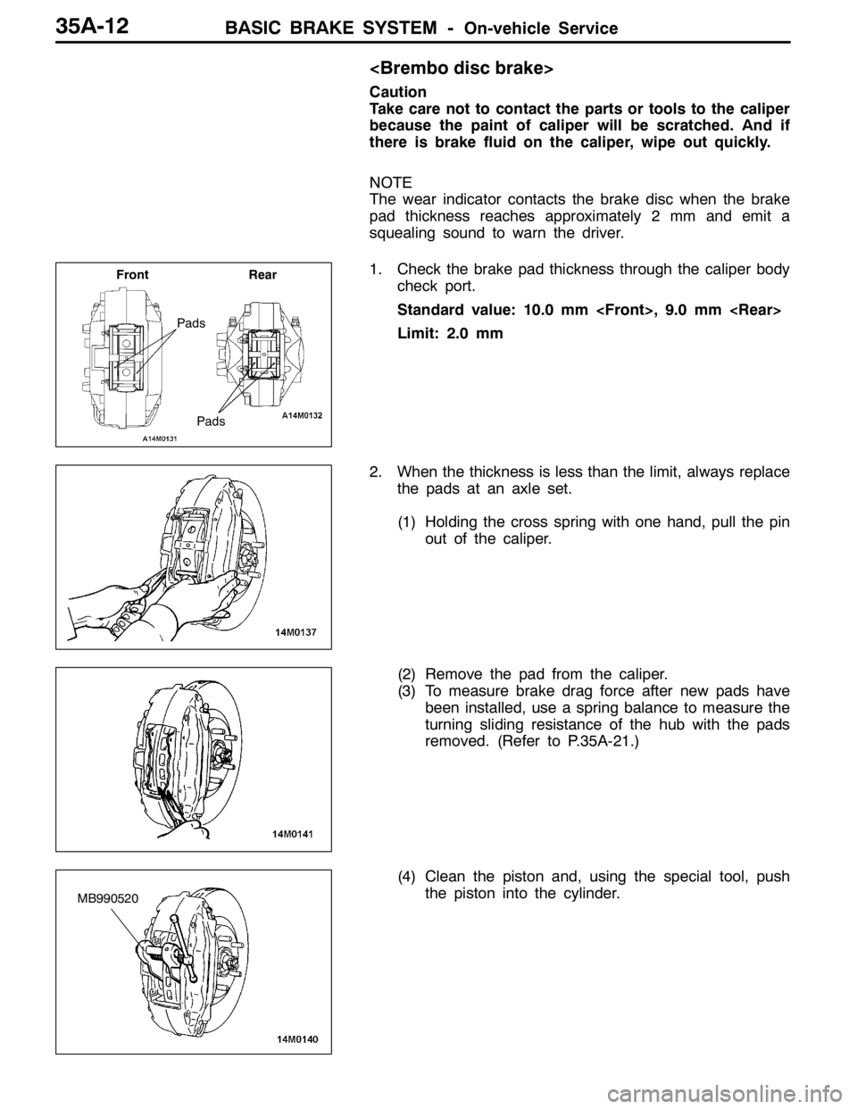
1. Check the brake pad thickness through the caliper body
check port.
Standard value: 10.0 mm
Limit: 2.0 mm
2. When the thickness is less than the limit, always replace
the pads at an axle set.
(1) Holding the cross spring with one hand, pull the pin
out of the caliper.
(2) Remove the pad from the caliper.
(3) To measure brake drag force after new pads have
been installed, use a spring balance to measure the
turning sliding resistance of the hub with the pads
removed. (Refer to P.35A-21.)
(4) Clean the piston and, using the special tool, push
the piston into the cylinder.
Pads
Front Rear
Pads
MB990520
Page 1055 of 1449
BASIC BRAKE SYSTEM -On-vehicle Service35A-13
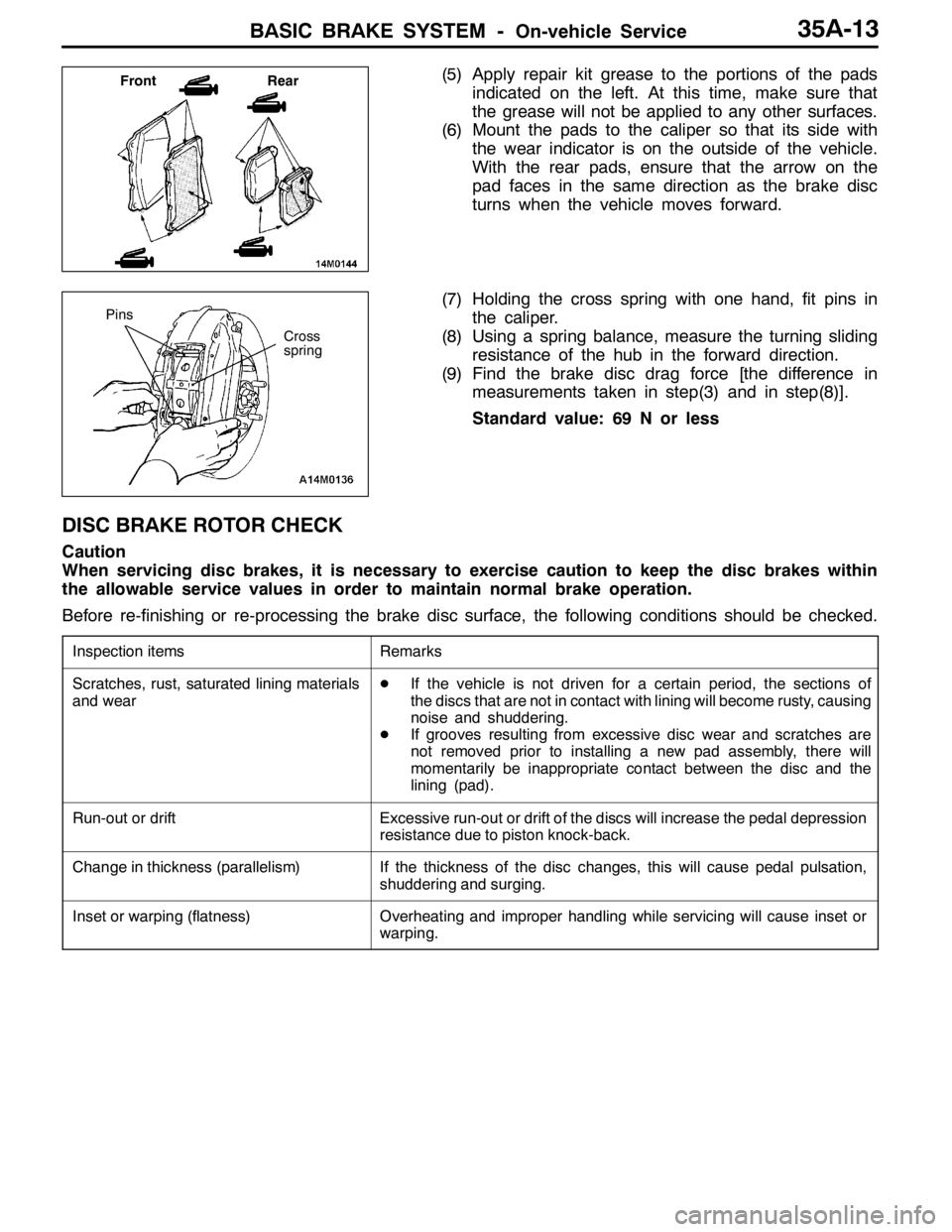
(5) Apply repair kit grease to the portions of the pads
indicated on the left. At this time, make sure that
the grease will not be applied to any other surfaces.
(6) Mount the pads to the caliper so that its side with
the wear indicator is on the outside of the vehicle.
With the rear pads, ensure that the arrow on the
pad faces in the same direction as the brake disc
turns when the vehicle moves forward.
(7) Holding the cross spring with one hand, fit pins in
the caliper.
(8) Using a spring balance, measure the turning sliding
resistance of the hub in the forward direction.
(9) Find the brake disc drag force [the difference in
measurements taken in step(3) and in step(8)].
Standard value: 69 N or less
DISC BRAKE ROTOR CHECK
Caution
When servicing disc brakes, it is necessary to exercise caution to keep the disc brakes within
the allowable service values in order to maintain normal brake operation.
Before re-finishing or re-processing the brake disc surface, the following conditions should be checked.
Inspection itemsRemarks
Scratches, rust, saturated lining materials
and wearDIf the vehicle is not driven for a certain period, the sections of
the discs that are not in contact with lining will become rusty, causing
noise and shuddering.
DIf grooves resulting from excessive disc wear and scratches are
not removed prior to installing a new pad assembly, there will
momentarily be inappropriate contact between the disc and the
lining (pad).
Run-out or driftExcessive run-out or drift of the discs will increase the pedal depression
resistance due to piston knock-back.
Change in thickness (parallelism)If the thickness of the disc changes, this will cause pedal pulsation,
shuddering and surging.
Inset or warping (flatness)Overheating and improper handling while servicing will cause inset or
warping.
Front Rear
Cross
spring
Pins
Page 1056 of 1449
BASIC BRAKE SYSTEM -On-vehicle Service35A-14
BRAKE DISC THICKNESS CHECK
Caution: Brembo disc brake
Take care not to contact the parts or tools to the caliper
because the paint of caliper will be scratched. And if
there is brake fluid on the caliper, wipe out quickly.
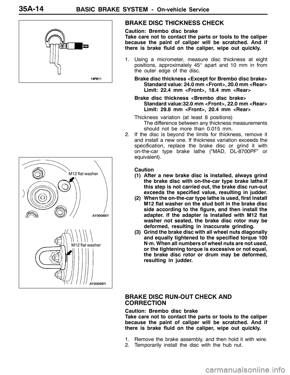
1. Using a micrometer, measure disc thickness at eight
positions, approximately 45°apart and 10 mm in from
the outer edge of the disc.
Brake disc thickness
Standard value: 24.0 mm
Limit: 22.4 mm
Brake disc thickness
Standard value:32.0 mm
Limit: 29.8 mm
Thickness variation (at least 8 positions)
The difference between any thickness measurements
should not be more than 0.015 mm.
2. If the disc is beyond the limits for thickness, remove it
and install a new one. If thickness variation exceeds the
specification, replace the brake disc or grind it with
on-the-car type brake lathe (“MAD, DL-8700PF” or
equivalent).
Caution
(1) After a new brake disc is installed, always grind
the brake disc with on-the-car type brake lathe.If
this step is not carried out, the brake disc run-out
exceeds the specified value, resulting in judder.
(2) When the on-the-car type lathe is used, first install
M12 flat washer on the stud bolt in the brake disc
side according to the figure, and then install the
adapter. If the adapter is installed with M12 flat
washer not seated, the brake disc rotor may be
deformed, resulting in inaccurate grinding.
(3) Grind the brake disc with all wheel nuts diagonally
and equally tightened to the specified torque 100
N·m. When all numbers of wheel nuts are not used,
or the tightening torque is excessive or not equal,
the brake disc rotor or drum may be deformed,
resulting in judder.
BRAKE DISC RUN-OUT CHECK AND
CORRECTION
Caution: Brembo disc brake
Take care not to contact the parts or tools to the caliper
because the paint of caliper will be scratched. And if
there is brake fluid on the caliper, wipe out quickly.
1. Remove the brake assembly, and then hold it with wire.
2. Temporarily install the disc with the hub nut.
M12 flat washer
M12 flat washer
Page 1057 of 1449

BASIC BRAKE SYSTEM -On-vehicle Service35A-15
3. Place a dial gauge approximately 5 mm from the outer
circumference of the brake disc, and measure the run-out
of the disc.
Limit: 0.03 mm or less
4. If the brake disc run-out exceeds the limit, correct it as
follows:
(1) Chalk phase marks on the wheel stud and the brake
disc, which run-out is excessive.
(2) Remove the brake disc. Then place a dial gauge
as shown, and measure the wheel bearing axial play
by pushing and pulling the wheel hub.
Limit: 0.06 mm
(3) If the wheel bearing axial play exceeds the limit,
disassemble the hub and knuckle assembly to check
each part.
(4) If the wheel bearing axial play does not exceed the
limit, dephase the brake disc and secure it. Then
recheck the brake disc run-out.
5. If the run-out cannot be corrected by changing the phase
of the brake disc, replace the brake disc or grind it with
the on-the-car type brake lathe ( “MAD, DL-8700PF” or
equivalent).
Caution
(1) After a new brake disc is installed, always grind
the brake disc with on-the-car type brake lathe.
If this step is not carried out, the brake disc run-out
exceeds the specified value, resulting in judder.
(2) When the on-the-car type lathe is used, first install
M12 flat washer on the stud bolt in the brake disc
side according to the figure, and then install the
adapter. If the adapter is installed with M12 flat
washer not seated, the brake disc rotor may be
deformed, resulting in inaccurate grinding.
(3) Grind the brake disc with all wheel nuts diagonally
and equally tightened to the specified torque 100
N·m. When all numbers of wheel nuts are not used,
or the tightening torque is excessive or not equal,
the brake disc rotor or drum may be deformed,
resulting in judder.
M12 flat washer
M12 flat washer
Page 1058 of 1449

BASIC BRAKE SYSTEM -Brake Pedal35A-16
BRAKE PEDAL
REMOVAL AND INSTALLATION
Post-installation Operation
Brake Pedal Adjustment (Refer to P.35A-7.)
1
2
3
64 8
7 5
12±2 N·m
14±3 N·m
Removal steps
1. Harness connector
2. Stop lamp switch
3. Adjuster
4. Pedal stopper
5. Snap pin6. Pin assembly
7. Pedal pad
"AA8. Brake pedal and pedal support
member
INSTALLATION SERVICE POINT
"AABRAKE PEDAL AND PEDAL SUPPORT MEMBER
INSTALLATION
Tighten the brake booster mounting nuts (A), and then the
brake pedal mounting bolts (B).
NOTE
The pedal support member can not be positioned correctly
if the pedal mounting bolts (B) are tightened first as the their
holes are oblong holes.
AA
BB
Page 1059 of 1449
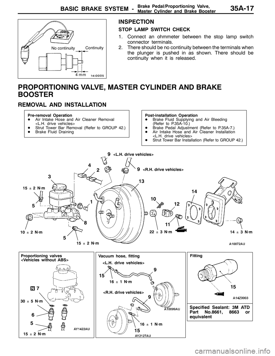
BASIC BRAKE SYSTEM -Brake Pedal/Proportioning Valve,
Master Cylinder and Brake Booster35A-17
INSPECTION
STOP LAMP SWITCH CHECK
1. Connect an ohmmeter between the stop lamp switch
connector terminals.
2. There should be no continuity between the terminals when
the plunger is pushed in as shown. There should be
continuity when it is released.
PROPORTIONING VALVE, MASTER CYLINDER AND BRAKE
BOOSTER
REMOVAL AND INSTALLATION
Pre-removal Operation
DAir Intake Hose and Air Cleaner Removal
DStrut Tower Bar Removal (Refer to GROUP 42.)
DBrake Fluid DrainingPost-installation Operation
DBrake Fluid Supplying and Air Bleeding
(Refer to P.35A-10.)
DBrake Pedal Adjustment (Refer to P.35A-7.)
DAir Intake Hose and Air Cleaner Installation
DStrut Tower Bar Installation (Refer to GROUP 42.)
510
11 3
12 4
14
15±2N·m 15±2N·m
22±3N·m
10±2N·m
13 2
8
14±3N·m
519
9
15±2N·m
5
Proportioning valves
67
30±5N·m
9
15
16±1N·m
9
15
16±1N·m
Vacuum hose, fitting
Specified Sealant: 3M ATD
Part No.8661, 8663 or
equivalent
15
Fitting
4mm
No continuityContinuity
Page 1060 of 1449

BASIC BRAKE SYSTEM -ProportioningValve,MasterCylinder
and Brake Booster35A-18
Master cylinder removal steps
1. Clutch hose connection
2. Brake fluid level sensor connector
3. Reservoir cap assembly
4. Brake fluid level sensor
5. Brake pipe connection
6. Proportioning valve
7. O ring
8. Master cylinder
Proportioning valve removal steps
5. Brake pipe connection
6. Proportioning valve
7. O ring
Brake booster removal steps
1. Clutch hose connection
2. Brake fluid level sensor connector5. Brake pipe connection
8. Master cylinder
"BADPush rod protrusion amount check and
adjustment
"AA9. Vacuum hose
(With built-in check valve)
10. Snap pin
11. Pin assembly
12. Clevis
DRemove A/C liquid pipe B
from the
retaining clip.(Refer to GROUP 55A
- Refrigerant Line.)
13. Brake booster
14. Sealer
Fitting removal steps
"AA9. Vacuum hose
(With built-in check valve)
15. Fitting
INSTALLATION SERVICE POINTS
"AAVACUUM HOSE CONNECTION
Insert the vacuum hose to the brake booster with its paint
mark facing upward, and then secure the hose by using the
hose clip.
"BAPUSH ROD PROTRUSION AMOUNT CHECK AND
ADJUSTMENT
1. Measure dimension (A).
Standard value (A) : 8.98 - 9.23 mm
NOTE
When a negative pressure of 66.7 kPa is applied to the
brake booster, the push rod should protrude 10.27 – 10.53
mm.
Block gauge Measuring distance A
A