MITSUBISHI LANCER EVOLUTION 2007 Service Repair Manual
Manufacturer: MITSUBISHI, Model Year: 2007, Model line: LANCER EVOLUTION, Model: MITSUBISHI LANCER EVOLUTION 2007Pages: 1449, PDF Size: 56.82 MB
Page 1291 of 1449

SRS - Post-collision Diagnosis52B-47
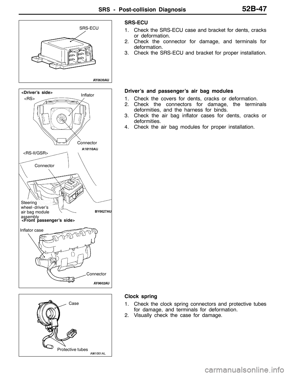
SRS-ECU
1. Check the SRS-ECU case and bracket for dents, cracks
or deformation.
2. Check the connector for damage, and terminals for
deformation.
3. Check the SRS-ECU and bracket for proper installation.
Driver’s and passenger’s air bag modules
1. Check the covers for dents, cracks or deformation.
2. Check the connectors for damage, the terminals
deformities, and the harness for binds.
3. Check the air bag inflator cases for dents, cracks or
deformities.
4. Check the air bag modules for proper installation.
Clock spring
1. Check the clock spring connectors and protective tubes
for damage, and terminals for deformation.
2. Visually check the case for damage.
SRS-ECU
Inflator
Connector
Connector
Steering
wheel - driver’s
air bag module
assembly
Connector Inflator case
Protective tubesCase
Page 1292 of 1449

SRS - Post-collision Diagnosis52B-48
Steering wheel, steering column and intermediate joint
1. Check the driver’s air bag module for proper installation
to the steering wheel.
2. Check the steering wheel for noise, binds or difficult
operation and excessive free play.
Harness connector (Instrument panel wiring harness,
Floor wiring harness)
Check the harness for binds, the connector for damage and
the terminals for deformation. (Refer to P.52B-44.)
Seat belt with pre-tensioner
1. Check the seat belt for damage or deformation.
2. Check the pre-tensioner for cracks or deformation.
3. Check the harness or the connector for damage, and
the terminal for deformation.
4. Check that the unit is installed correctly to the vehicle
body.
Page 1293 of 1449

SRS - Individual Component Service/Warning/Caution Labels52B-49
INDIVIDUAL COMPONENT SERVICE
If the SRS components and seat belt with pre-tensioner are to be removed or replaced as a result of
maintenance, troubleshooting etc., follow the service procedures that follow.
Caution
1. SRS components and seat belt with pre-tensioner should not be subjected to heat, so remove
the SRS-ECU, driver’s air bag module
passenger’s air bag module, clock spring, and seat belt with pre-tensioner before drying or
baking the vehicle after painting.
DFront impact sensor, SRS-ECU, Air bag module, clock spring: 93_C or more
DSeat belt with pre-tensioner: 90_C or more
Recheck SRS system operability after re-installing them.
2. If the SRS components and seat belt with pre-tensioner are removed for the purpose of check,
sheet metal repair, painting, etc., they should be stored in a clean, dry place until they are
reinstalled.
WARNING/CAUTION LABELS
Caution labels on the SRS are attached in the
vehicle as shown. Follow label instructions whenservicing the SRS. If the label(s) are dirty or
damaged, replace with new one(s).
Steering wheel
Driver’s air bag module
Clock springFront passenger’s
air bag moduleSRS-ECU
Sun visor
Steering joint cover
Glove boxCover
Seat belt with pre-tensioner
Page 1294 of 1449

SRS - SRS-ECU52B-50
SRS AIR BAG CONTROL UNIT (SRS-ECU)
Caution
1. Disconnect the negative ( - ) battery terminal
and wait for 60 seconds or more before
starting work. Also, the disconnected
battery terminal should be insulated with
tape. (Refer to P.52B-3.)
2. Never attempt to disassemble or repair the
SRS-ECU. If faulty, just replace with a new
one.3. Do not drop or subject the SRS-ECU to
impact or vibration.
If denting, cracking, deformation, or rust are
found in the SRS-ECU, replace it with a new
one. Discard the old one.
4. After deployment of the air bags, replace
the SRS-ECU with a new one.
5. Never use an ohmmeter on or near the
SRS-ECU, and use only the special test
equipment described on P.52B-6.
REMOVAL AND INSTALLATION
Pre-removal Operation
DTurn Ignition Key to LOCK (OFF) Position.
DDisconnect the Negative ( - ) Battery Terminal.
12
4.9±1.0 N·m
4.9±1.0 N·m
4.9±1.0 N·m
3
Removal steps
DFront floor console
(Refer to GROUP 52A - Front floor
console.)
DRear heater duct B
1. SRS-ECU and SRS-ECU bracket
assembly
2. SRS-ECU
3. SRS-ECU bracketInstallation steps
3. SRS-ECU bracket
"AA2. SRS-ECU
1. SRS-ECU and SRS-ECU bracket
assembly
DRear heater duct B
DFront floor console
(Refer to GROUP 52A - Front floor
console.)
DNegative ( - ) battery terminal
connection
"BADPost-installation inspection
Page 1295 of 1449

SRS - SRS-ECU52B-51
INSTALLATION SERVICE POINTS
"AASRS-ECU INSTALLATION
Caution
Be sure to install the SRS-ECU properly. Otherwise, the
SRS air bags do not activate, which results in serious
injury or death of vehicle’s occupants.
"BAPOST-INSTALLATION CHECK
1. Turn the ignition switch to ON.
2. Does the SRS warning lamp illuminate for about 7 seconds
and then go out.
Yes: The SRS warning lamp is working properly
No: Go to Troubleshooting. (Refer to P.52B-6.)
INSPECTION
1. Check the SRS-ECU and brackets for dents, cracks or
deformation.
2. Check connector for damage, and terminals for
deformation.
Caution
If a dent, crack, deformation or rust are present,
replace the SRS-ECU with a new one.
NOTE
To check the SRS-ECU in other items than described
above, go to Troubleshooting. (Refer to P.52B-6.)
SRS warning lamp
Page 1296 of 1449

SRS - Air Bag Modules and Clock Spring52B-52
AIR BAG MODULES AND CLOCK SPRING
Caution
1. Disconnect the negative ( - ) battery terminal
and wait for 60 seconds or more before
starting work. Also, the disconnected
battery terminal should be insulated with
tape. (Refer to P.52B-3.)
2. Never attempt to disassemble or repair the
air bag modules and clock spring.
If faulty, just replace with new one(s).
3. Do not drop the air bag modules or clock
spring or allow contact with water, grease
or oil.
Replace if a dent, crack, deformation or rust
are present.
4. Store the air bag modules on a flat surface
with the deployment surface facing up.
Do not place anything on top of them.5. Do not store the air bag modules in a place
more than 93_C.
6. When the driver’s and front passenger’s air
bags have been deployed, replace the
driver’s and passenger’s air bag modules
with new ones.
7. Put on gloves and safety glasses when
handling deployed air bags.
8. When discarding the undeployed air bag
module(s), be sure to deploy the air bag(s)
in advance as specified in the service
procedure. (Refer to to P.52B-64.)
Page 1297 of 1449

SRS - Air Bag Modules and Clock Spring52B-53
REMOVAL AND INSTALLATION
Pre-removal Operation
Disconnect the Negative ( - ) Battery Terminal.
3 2
41
0.9±0.2 N·m
0.9±0.2 N·m41±8 N·m
Driver’s air bag module removal
steps
AA"1. Driver’s air bag moduleDriver’s air bag module installation
steps
"AADPre-installation inspection
1. Driver’s air bag module
DNegative ( - ) terminal of the battery
connection
"DADPost-installation inspection
Clock spring removal steps
AA"1. Driver’s air bag module
AB"2. Steering wheel
3. Lower column cover
AC"4. Clock springClock spring installation steps
"AADPre-installation inspection
"BA4. Clock spring
3. Lower Column Cover
"CA2. Steering wheel
1. Driver’s air bag module
DNegative ( - ) terminal of the battery
connection
"DADPost-installation inspection
Page 1298 of 1449

SRS -Air Bag Modules and Clock Spring52B-54
3 2
4
1
50±5 N·m
2
Steering wheel - driver’s air bag
module assembly removal steps
AD"1. Cover
AE"2. Steering wheel - driver’s air bag
module assemblySteering wheel - driver’s air bag
module assembly installation steps
"AADPre-installation inspection
2. Steering wheel - driver’s air bag
module assembly
1. Cover
DNegative ( - ) terminal of the battery
connection
"DADPost-installation inspection
Clock spring removal steps
AD"1. Cover
AE"2. Steering wheel - driver’s air bag
module assembly
3. Lower Column Cover
AC"4. Clock springClock spring installation steps
"AADPre-installation inspection
"BA4. Clock spring
3. Lower Column Cover
"CA2. Steering wheel - driver’s air bag
module assembly
1. Cover
DNegative ( - ) terminal of the battery
connection
"DADPost-installation inspection
Page 1299 of 1449

SRS - Air Bag Modules and Clock Spring52B-55
1
Removal steps
DInstrument panel assembly
(Refer to GROUP 52A - Instrument
panel.)
A
F"1. Passenger’s air bag moduleInstallation steps
"AADPre-installation inspection
1. Passenger’s air bag module
DInstrument panel assembly
(Refer to GROUP 52A - Instrument
panel.)
DNegative ( - ) battery cable connection
"DADPost-installation inspection
REMOVAL SERVICE POINTS
AA"DRIVER’S AIR BAG MODULE REMOVAL
1. Remove the air bag module mounting screw (torque
screw) from the steering wheel side.
2. Spread the lock outward to remove the connector by
prying with a flat-tipped screw driver as shown in the
illustration at left.
Caution
(1) Be careful not to remove the connector forcibly.
(2) Keep the removed driver’s air bag module facing
the pad surface upward in a clean and dry place.
locked
Connector
Flat-tipped screw
driver
locked
Page 1300 of 1449

SRS - Air Bag Modules and Clock Spring52B-56
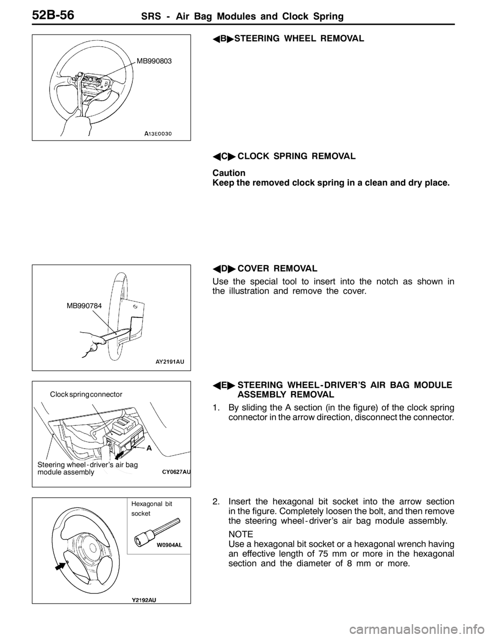
AB"STEERING WHEEL REMOVAL
AC"CLOCK SPRING REMOVAL
Caution
Keep the removed clock spring in a clean and dry place.
AD"COVER REMOVAL
Use the special tool to insert into the notch as shown in
the illustration and remove the cover.
AE"STEERING WHEEL - DRIVER’S AIR BAG MODULE
ASSEMBLY REMOVAL
1. By sliding the A section (in the figure) of the clock spring
connector in the arrow direction, disconnect the connector.
2. Insert the hexagonal bit socket into the arrow section
in the figure. Completely loosen the bolt, and then remove
the steering wheel - driver’s air bag module assembly.
NOTE
Use a hexagonal bit socket or a hexagonal wrench having
an effective length of 75 mm or more in the hexagonal
section and the diameter of 8 mm or more.
MB990803
MB990784
A Clock spring connector
Steering wheel - driver’s air bag
module assembly
Hexagonal bit
socket