MITSUBISHI LANCER EVOLUTION 2007 Service Repair Manual
Manufacturer: MITSUBISHI, Model Year: 2007, Model line: LANCER EVOLUTION, Model: MITSUBISHI LANCER EVOLUTION 2007Pages: 1449, PDF Size: 56.82 MB
Page 1251 of 1449

SRS -Troubleshooting52B-7
SRS SYSTEM CIRCUIT DIAGRAM
Ignition switch (IG1)
J/B
(common fuse)
Combination
Meter
Connector lock switch*
ON
ON OFF
OFF
Driver’s air
bag module
(squib)
Front pas-
senger’s seat
air bag mod-
ule(squib)
Seat belt
pre-tensioner
(L.H.)Clock spring
ONONOFF
OFF
Connector lock switch* Diagnosis connector SRS-ECU
No.3
7.5A No.2
7.5A
OFF
OFF
OFF
OFF
OFF
OFF
OFF
OFFON
ON
ON
ON
ON
ON
ON
ONOFF
ON
ON OFF
C-207
C-204
C-109
D-28
D-26C-22
SRS - ECU connector16
13
7 8
11
12
10
9
30
29
28
2720 Connector lock switch*
Connector lock switch*
Connector lock switch*
Connector lock switch*
Connector lock switch*
NOTE
*:connector engaged:ON
connector disengaged:OFF Seat belt
pre-tensioner
(R.H.)
Page 1252 of 1449

SRS -Troubleshooting52B-8
CONNECTOR FOR SRS AIR BAG
The SRS air bag system connector is yellow or red.
To enhance system reliability, a connector lock switch is adopted for the SRS-ECU connector, and each
air bag module and clock spring connector, each seat belt with pre-tensioner
AClock
spring
SRS-ECUDriver’s air bag module
Front passenger’s air bag module A
A ADriver’s seat belt pre-tensioner
Front passenger’s seat belt pre-tensioner
SQUIB CIRCUIT CONNECTOR LOCK SWITCH
Mechanism to automatically short-circuit the power supply terminal and the earth terminal of the air bag squib
circuit when the connector is disconnected. The short spring inside the connector allows to short-circuit the
power supply terminal and the earth terminal of the squib (no difference in voltage occurs between the
terminals) to prevent the squib from getting charged with static electricity.
CAUTION
When the connector is disconnected, it is normal for short-circuiting to occur between the connector
terminals.
When connector is connected
When connector is disconnectedOFF
ON
OFFOFF
OFF
ONON
ON
ECU side connectorHarness side connector
A A
Short spring
Partition panelTerminal
(Female) Terminal
(Male)B
BSection A - A
Section B - B
Partition
panelShort springTerminal
(Female)
Terminal
(Male)When connector is connected
Partition panel
Terminal
(Female) Te r m i n a l
(Male) SquibSquib
SRS-ECUSRS-ECU
Short spring
Page 1253 of 1449

SRS -Troubleshooting52B-9
WARNING LAMP CIRCUIT CONNECTOR LOCK SWITCH
Mechanism to automatically short-circuit the power supply
terminal and the earth terminal of the warning lamp circuit
when the SRS-ECU connector is disconnected. The structure
is the same as that of squib circuit connector lock switch.
INSPECTION CHART FOR DIAGNOSIS CODES
Inspect according to the inspection chart that is appropriate for the malfunction code.
Code no.Diagnostic itemPage
14SRS-ECU front impact analog G-sensor system52B-11
15SRS-ECU front impact safing G-sensor systemShort circuit in the
sensor52B-11
16SRS-ECU front impact safing G-sensor systemOpen circuit in the
sensor
21*1Driver’s air bag module (squib) systemShort circuit between
terminals of the squib
circuit52B-12
22*1Driver’s air bag module (squib) systemOpen in the squib
circuit52B-16
24*1Front passenger’s air bag module (squib) systemShort circuit between
terminals of the squib
circuit52B-20
25*1Front passenger’s air bag module (squib) systemOpen in the squib
circuit52B-22
26*1Driver’s seat belt pre-tensioner (squib) systemShort circuit between
terminals of the squib
circuit52B-23
27*1Driver’s seat belt pre-tensioner (squib) systemOpen in the squib
circuit52B-25
28*1Front passenger’s seat belt pre-tensioner (squib) systemShort circuit between
terminals of the squib
circuit52B-26
29*1Front passenger’s seat belt pre-tensioner (squib) system/Open in the squib
circuit52B-28
31SRS-ECU DC-DC converter systemIncreased terminal
voltage52B-11
32SRS-ECU DC-DC converter systemDecreased terminal
voltage
Ignition switch (IG1)
SRS warning lamp
SRS-ECU harness
side connector
Short spring
ON
ONOFF
OFF Connector*
lock switch
NOTE
*:connector engaged:ON
connector disengaged:OFF
Page 1254 of 1449

SRS -Troubleshooting52B-10
Code no.Page Diagnostic item
34*2Connector lock system52B-29
35SRS-ECU (deployed air bag) system52B-29
41*2Power supply circuit system (fuse No.2 circuit)52B-30
42*2Power supply circuit system (fuse No.3 circuit)52B-32
43*2SRS warning lamp drive circuit systemLamp does not illumi-
nate.52B-33
SRS warning lamp drive circuit systemLamp does not go out.52B-33
44*2SRS warning lamp drive circuit system52B-33
45SRS-EUC internal circuit system including non - volatile memory (EEPROM)52B-11
51Driver’s air bag module (squib) ignition drive circuit systemShort in the ignition
drive circuit52B-11
52Driver’s air bag module (squib) ignition drive circuit systemOpen in the ignition
drive circuit
54Front passenger’s air bag (squib) ignition drive circuit
systemShort in the ignition
drive circuit52B-11
55Front passenger’s air bag (squib) ignition drive circuit
systemOpen in the ignition
drive circuit
56Driver’s seat belt pre-tensioner (squib) ignition drive circuit
systemShort in the ignition
drive circuit52B-11
57Driver’s seat belt pre-tensioner (squib) ignition drive circuit
systemOpen in the ignition
drive circuit
58Front passenger’s seat belt pre-tensioner (squib) ignition
drive circuit systemShort in the ignition
drive circuit52B-11
59Front passenger’s seat belt pre-tensioner (squib) ignition
drive circuit systemOpen in the ignition
drive circuit
61Driver’s air bag module (squib) systemShort-circuited to
power supply52B-34
62Driver’s air bag module (squib) systemShort-circuited to earth
64Front passenger’s air bag module (squib) systemShort-circuited to
power supply52B-38
65Front passenger’s air bag module (squib) systemShort-circuited to earth
66Driver’s seat belt pre-tensioner (squib) systemShort-circuited to
power supply52B-39
67Driver’s seat belt pre-tensioner (squib) systemShort-circuited to earth
68Front passenger’s seat belt pre-tensioner (squib) systemShort-circuited to
power supply52B-40
69Front passenger’s seat belt pre-tensioner (squib) systemShort-circuited to earth
NOTE
(1) *1: If the trouble(s) are removed, the SRS warning lamp go out with diagnosis code history stored.
(2) *2: If the trouble(s) are removed, the SRS warning lamp will go out with diagnosis code history automatically erased.
(3) When the battery has been discharged, diagnosis code No.41 or 42 is stored. Check the battery when either of
these is displayed.
Page 1255 of 1449

SRS -Troubleshooting52B-11
INSPECTION PROCEDURE CLASSIFIED BY DIAGNOSIS CODE
Code No.14, 15, 16, 31, 32, 45, 51, 52, 54, 55, 56, 57, 58, 59
System inside SRS-ECUProbable cause
Malfunction is present inside SRS-ECU. See table below for what each code
tells.DMalfunction of SRS-ECU
Code No.Defective partsTrouble
14Front impact analog G-sensorDNot operating
DAbnormal characteristics
DAbnormal output
15Front impact safing G-sensorDShort in the circuit
16DOpen in the circuit
31DC-DC converterDTerminal voltage of the converter higher than specified for
five seconds or more
32DTerminal voltage of the converter lower than specified for
5 seconds or more (this code is not detected when code
No.41 or 42, which indicates discharged battery, has been
detected)
45Non-volatile memory (EEPROM)DDefective parts inside
51Driver’sairbagmodule(squib)DShortinthecircuit51Driver’sairbag module(squib)
ignitiondrivecircuit
DShortinthecircuit
52ignition drive circuitDOpen in the circuit
54Front passenger’s air bag module
(squib)ignitiondrivecircuit
DShort in the circuit
55(squib)ignitiondrive circuitDOpen in the circuit
56Driver’s seat belt pre-tensioner
(squib)ignitiondrivecircuit
DShort in the circuit
57(squib)ignitiondrive circuitDOpen in the circuit
58Front passenger’s seat belt pre-ten-
sioner(squib)ignitiondrivecircuit
DShort in the circuit
59sioner(squib)ignitiondrive circuitDOpen in the circuit
If the above - mentioned code No. is output, replace the SRS-ECU.
Page 1256 of 1449

SRS -Troubleshooting52B-12
Code No.21 Driver’s air bag module (squib) systemPossible Cause
This code is output when short circuit occurs between terminals of the
SRS-ECU driver’s air bag module (squib) circuit.
However, SRS warning lamp goes out when a normal operation is resumed
(diagnosis code is not cleared.)DConnector engagement faulty or short bar faulty*
DShort circuit in the clock spring
DShort circuit between terminals of the driver’s air
bag module (squib) circuit
DFaulty connector
DSRS-ECU inoperable
NOTE:
(1) *: The connector of the squib circuit contains a short bar (short-circuiting the positive (+) cable and
the negative ( - ) cable to avoid an erroneous deployment caused by static electricity when a connector
is not connected). Thus, when a connector is connected, the short bar may not be released due
to improper engagement of the connector or faulty connector as shown in the illustration below.
Disconnect the connector as shown in the illustration below, then reconnect it. Check that a diagnosis
code is output again after erasing the memory. If the diagnosis code is not output, the above-mentioned
code is output due to improper engagement of the connector.
C-204C-207
SRS-ECU
Clock spring
Driver’s air bag module C-21
(2) Two different types of driver’s air bag modules by model are featured. Thus, two types of air bag
module by model are described in the following flowchart.
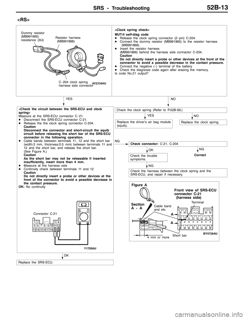
RS: Steering wheel and air bag module separate type
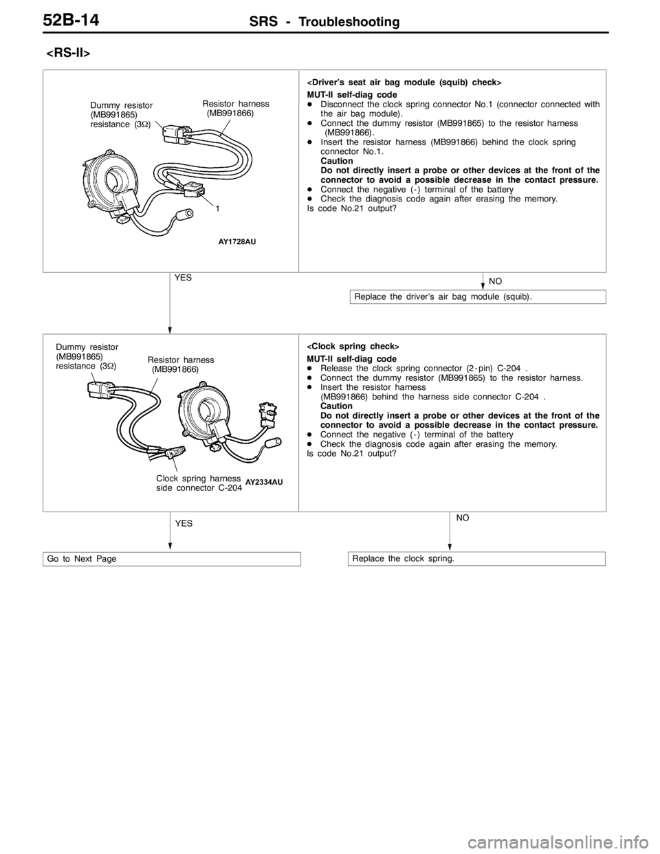
RS-II: Steering wheel and air bag module incorporate type
Page 1257 of 1449

SRS -Troubleshooting52B-13
NG
Measure at the SRS-ECU connector C - 21.
DDisconnect the SRS-ECU connector C-21.
DRelease the the clock spring connector C-204.
Caution
Disconnect the connector and short-circuit the squib
circuit before releasing the short bar of the SRS-ECU
connector in the following operation.
DCable bands between terminals 11, 12 and the short bar
(width:3 mm, thickness:0.5 mm) between terminals 11 and
12 and the short bar, and release the short bar.
(See Figure A.)
Caution
As the short bar may not be releasable if inserted
insufficiently, insert more than 4 mm.
DMeasure at the harness side
DContinuity check between terminals 11 and 12
Caution
Do not directly insert a probe or other devices at the
front of the connector to avoid a possible decrease in
the contact pressure.
OK:No continuity
Check connector:C-21, C-204
MUT-II self-diag code
DRelease the clock spring connector (2 - pin) C-204.
DConnect the dummy resistor (MB991865) to the resistor harness
(MB991866).
DInsert the resistor harness
(MB991866) behind the harness side connector C-204.
Caution
Do not directly insert a probe or other devices at the front of the
connector to avoid a possible decrease in the contact pressure.
DConnect the negative ( - ) terminal of the battery
DCheck the diagnosis code again after erasing the memory.
Is code No.21 output?
Resistor harness
(MB991866)
C - 204 clock spring
harness side connector
YES Dummy resistor
(MB991865)
resistance (3Ω)
Check the clock spring (Refer to P.52B-59.)
NOYES
Replace the clock spring.Replace the driver’s air bag module
(squib).NO
Check the harness between the clock spring and the
SRS-ECU, and repair if necessary.
Check the trouble
symptoms.Correct
OK
NG NG
Replace the SRS-ECU.
OK
Figure A
Terminal
Short bar
Front view of SRS-ECU
connector C-21
(harness side)
Cable band
and etc.Section
A-A
4 mm or more
A
AConnector C-21
Page 1258 of 1449

SRS -Troubleshooting52B-14
MUT-II self-diag code
DDisconnect the clock spring connector No.1 (connector connected with
the air bag module).
DConnect the dummy resistor (MB991865) to the resistor harness
(MB991866).
DInsert the resistor harness (MB991866) behind the clock spring
connector No.1.
Caution
Do not directly insert a probe or other devices at the front of the
connector to avoid a possible decrease in the contact pressure.
DConnect the negative ( - ) terminal of the battery
DCheck the diagnosis code again after erasing the memory.
Is code No.21 output? Dummy resistor
(MB991865)
resistance (3Ω)
1
YESNO
Replace the driver’s air bag module (squib). Resistor harness
(MB991866)
Go to Next Page
MUT-II self-diag code
DRelease the clock spring connector (2 - pin) C-204 .
DConnect the dummy resistor (MB991865) to the resistor harness.
DInsert the resistor harness
(MB991866) behind the harness side connector C-204 .
Caution
Do not directly insert a probe or other devices at the front of the
connector to avoid a possible decrease in the contact pressure.
DConnect the negative ( - ) terminal of the battery
DCheck the diagnosis code again after erasing the memory.
Is code No.21 output?
YESNO
Replace the clock spring. Resistor harness
(MB991866)
Clock spring harness
side connector C-204 Dummy resistor
(MB991865)
resistance (3Ω)
Page 1259 of 1449

SRS -Troubleshooting52B-15
OKNG
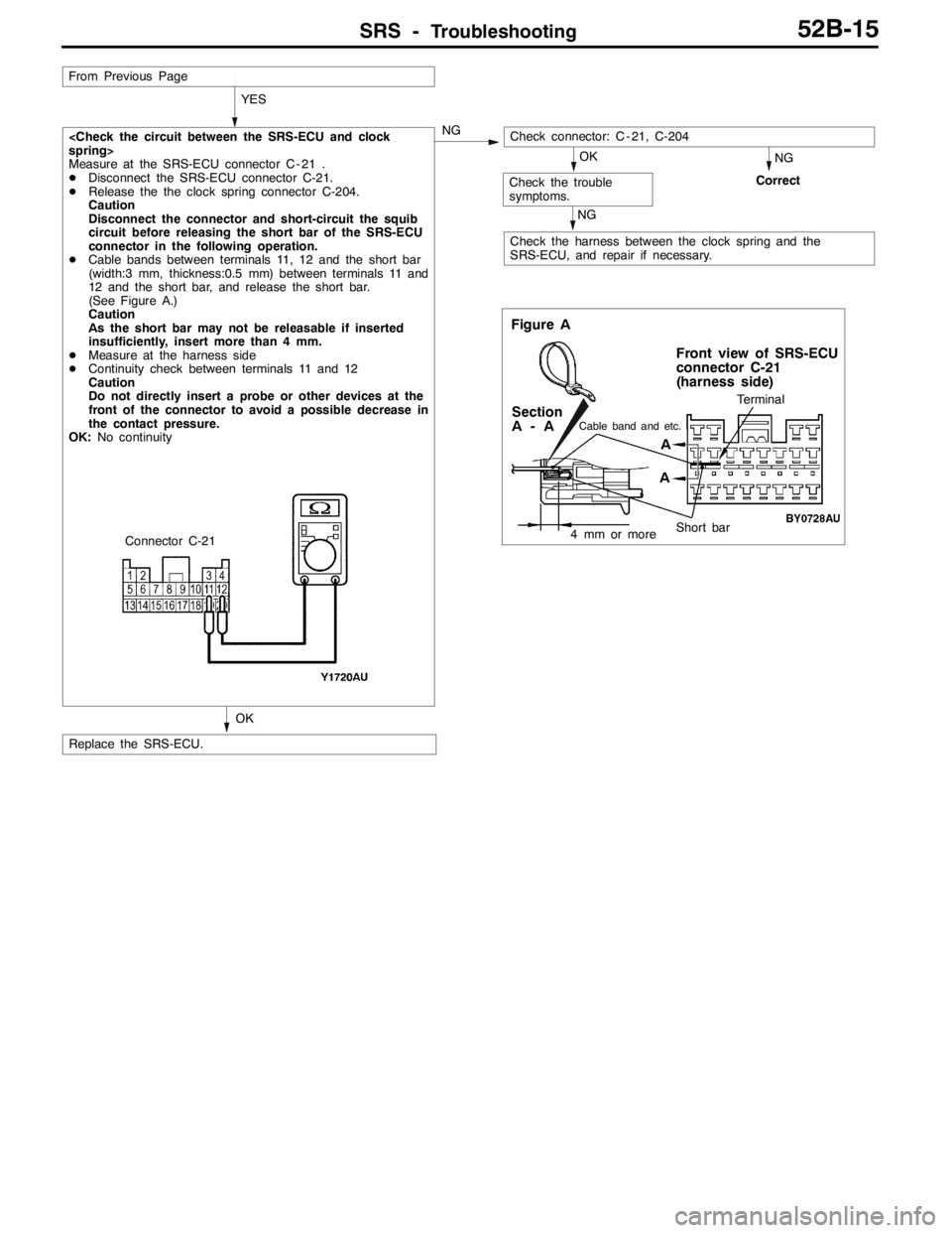
Measure at the SRS-ECU connector C - 21 .
DDisconnect the SRS-ECU connector C-21.
DRelease the the clock spring connector C-204.
Caution
Disconnect the connector and short-circuit the squib
circuit before releasing the short bar of the SRS-ECU
connector in the following operation.
DCable bands between terminals 11, 12 and the short bar
(width:3 mm, thickness:0.5 mm) between terminals 11 and
12 and the short bar, and release the short bar.
(See Figure A.)
Caution
As the short bar may not be releasable if inserted
insufficiently, insert more than 4 mm.
DMeasure at the harness side
DContinuity check between terminals 11 and 12
Caution
Do not directly insert a probe or other devices at the
front of the connector to avoid a possible decrease in
the contact pressure.
OK:No continuity
Replace the SRS-ECU.
Figure A
Terminal
Short bar
Front view of SRS-ECU
connector C-21
(harness side)
Cable band and etc.Section
A-A
4 mm or more
A
A
Connector C-21
YES
From Previous Page
Check the harness between the clock spring and the
SRS-ECU, and repair if necessary.
Check connector: C - 21, C-204
Check the trouble
symptoms.
NG
CorrectOK
NG
Page 1260 of 1449

SRS -Troubleshooting52B-16
Code No.22 Driver’s air bag module (squib) systemPossible Cause
This code is output when open circuit occurs in the SRS-ECU driver’s air bag
module (squib) circuit.
However, SRS warning lamp goes out when a normal operation is resumed
(diagnosis code is not cleared.)DOpen in the clock spring
DHalf open in the circuit due to improper neutral
positioning of the clock spring
DOpen in the driver’s air bag module (squib) circuit
DDriver’s air bag module (squib) connector falling
out
DConnector improper contact
DSRS-ECU inoperable
NOTE:
Two different types of driver’s air bag modules by model are featured. Thus, two types of air bag module
by model are described in the following flowchart.
RS: Steering wheel and air bag module separate type
RS-II: Steering wheel and air bag module incorporate type