lock MITSUBISHI LANCER EVOLUTION 2007 Service Repair Manual
[x] Cancel search | Manufacturer: MITSUBISHI, Model Year: 2007, Model line: LANCER EVOLUTION, Model: MITSUBISHI LANCER EVOLUTION 2007Pages: 1449, PDF Size: 56.82 MB
Page 1184 of 1449

BODY -DoorsBODY -Doors42-36
"BALOWER SASH INSTALLATION
Be sure to install the lower sash to the window rear sash
(at door) securely.
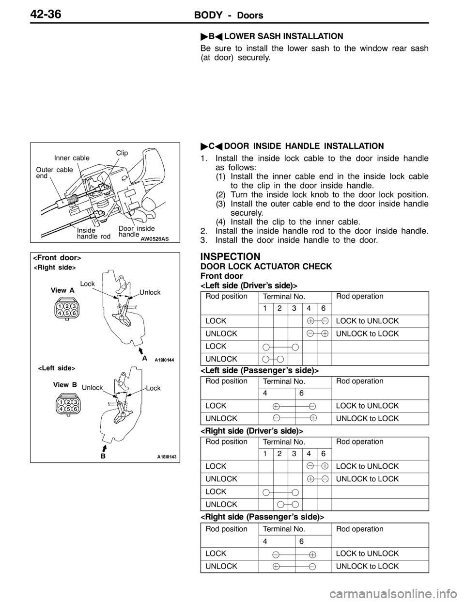
"CADOOR INSIDE HANDLE INSTALLATION
1. Install the inside lock cable to the door inside handle
as follows:
(1) Install the inner cable end in the inside lock cable
to the clip in the door inside handle.
(2) Turn the inside lock knob to the door lock position.
(3) Install the outer cable end to the door inside handle
securely.
(4) Install the clip to the inner cable.
2. Install the inside handle rod to the door inside handle.
3. Install the door inside handle to the door.
INSPECTION
DOOR LOCK ACTUATOR CHECK
Front door
Rod positionTerminal No.Rod operation
12346
LOCKLOCK to UNLOCK
UNLOCKUNLOCK to LOCK
LOCK
UNLOCK
Rod positionTerminal No.Rod operation
46
LOCKLOCK to UNLOCK
UNLOCKUNLOCK to LOCK
Rod positionTerminal No.Rod operation
12346
LOCKLOCK to UNLOCK
UNLOCKUNLOCK to LOCK
LOCK
UNLOCK
Rod positionTerminal No.Rod operationp
46
p
LOCKLOCK to UNLOCK
UNLOCKUNLOCK to LOCK
Door inside
handle
Inner cableClip
Outer cable
end
Inside
handle rod
B Unlock
View B
Lock
View A
Unlock Lock
A
Page 1185 of 1449

BODY -Doors42-37
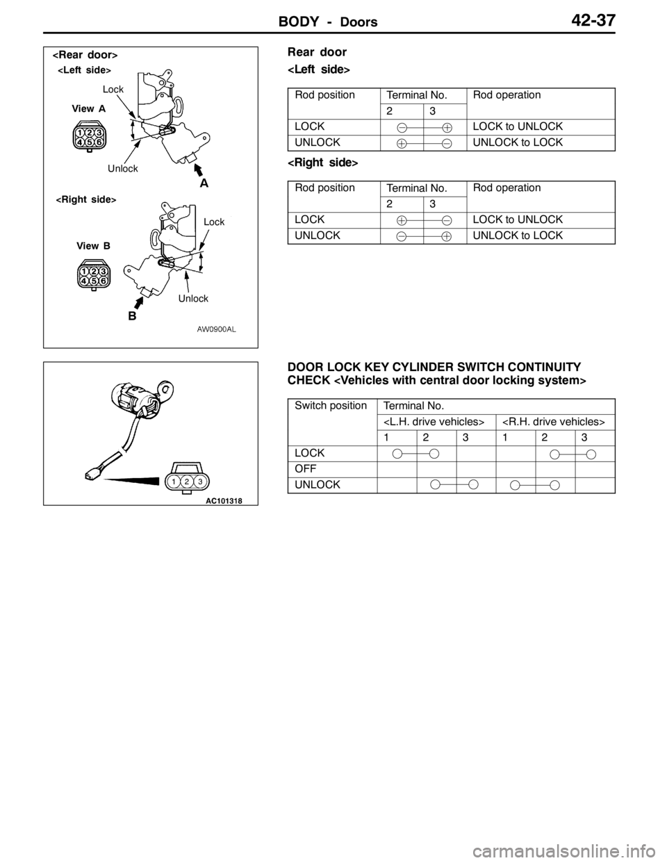
Rear door
Rod positionTerminal No.Rod operationp
23
p
LOCKLOCK to UNLOCK
UNLOCKUNLOCK to LOCK
Rod positionTerminal No.Rod operationp
23
p
LOCKLOCK to UNLOCK
UNLOCKUNLOCK to LOCK
DOOR LOCK KEY CYLINDER SWITCH CONTINUITY
CHECK
Switch positionTerminal No.p
123123
LOCK
OFF
UNLOCK
BA
View ALock
Unlock
View B
UnlockLock
Page 1189 of 1449

BODY -Trunk lid42-41
TRUNK LID
REMOVAL AND INSTALLATION
2
34 56
7 89 10
111
12A
A
B
B5 5
99
14Measure of
length mm
15
4 9
12
8.9±1.9 N·m
Section A - A
Section B - B
Trunk lid weatherstrip removal
steps
DRear end trim
GROUP 52A.)
"BA1. Trunk lid weatherstrip
Trunk lid release cable and trunk
lid release handle removal steps
DTrunk rear side trim (Left side)
(Refer to GROUP 52A.)
DRear seat (Refer to GROUP 52A.)
DCenter pillar lower trim (Refer to
GROUP 52A.)
DCowl side trim
DAccelerator pedal stopper
2. Trunk lid release handle
3. Trunk lid release cable
Trunk lid striker removal steps
DRear end trim
GROUP 52A.)4. Trunk lid striker
Trunk lid panel removal steps
5. Trunk lid bumper
6. Trunk lid lock cylinder
7. Trunk lid latch assembly
8. Trunk lid hinge mounting bolt
9. Trunk lid panel assembly
Trunk lid latch assembly removal
7. Trunk lid latch assembly
Trunk lid hinge removal steps
DRear shelf trim
DRear seat (Refer to GROUP 52A.)
9. Trunk lid panel assembly
AA""AA10. Trunk lid torsion bar (Right side)
AA""AA11. Trunk lid torsion bar (Left side)
12. Trunk lid hinge
Page 1220 of 1449

52A-2
INTERIOR
CONTENTS
SPECIAL TOOL 3............................
INSTRUMENT PANEL* 3......................
FRONT FLOOR CONSOLE 10................
REAR FLOOR CONSOLE 12..................
TRIMS 15....................................
HEADLINING 17..............................SEAT 19.....................................
Front Seat 19..................................
Rear Seat 22..................................
SEAT BELT 25...............................
Front Seat Belt 25.............................
Rear Seat Belt 26..............................
WARNINGS REGARDING SERVICING OF SUPPLEMENTAL RESTRAINT SYSTEM (SRS) EQUIPPED VEHICLES
WARNING!
(1) Improper service or maintenance of any component of the SRS, or any SRS-related component, can lead to personal
injury or death to service personnel (from inadvertent firing of the air bag) or to the driver and passenger (from rendering
the SRS inoperative).
(2) Service or maintenance of any SRS component or SRS-related component must be performed only at an authorized
MITSUBISHI dealer.
(3) MITSUBISHI dealer personnel must thoroughly review this manual, and especially its GROUP 52B - Supplemental
Restraint System (SRS) before beginning any service or maintenance of any component of the SRS or any SRS-related
component.
NOTE
The SRS includes the following components: SRS-ECU, SRS warning lamp, air bag module, clock spring and interconnecting
wiring. Other SRS-related components (that may have to be removed/installed in connection with SRS service or maintenance) are
indicated in the table of contents by an asterisk (*).
Page 1222 of 1449

INTERIOR -Instrument Panel52A-4
Caution: SRS
1. Refer to GROUP 52B-SRS Service Precautions and Air bag Module and Clock Spring before
removing the passenger side air bag module.
2. Do not subject the SRS-ECU to any shocks when removing or installing the instrument panel.
Pre-removal and Post-installation Operation
DRemoval and Installation of Front Pillar Trim (Refer
to P.52A-15.)
DFood Opener Lever (Refer to GROUP42.)
22 22
23
19
20 24
1817 11
12
10 6
7
1315 4
16 8 9
5
21 14 13 2
b b
d
d c
bdd
bd d
ad
ca
d
a25
d
Removal steps
1. Column cover
2. Meter bezel
3. Combination meter
4. Instrument panel ornament
5. Under cover
6. Box
7. Switch panel
8. Side box
9. Lower frame
10. Heater control knob
11. Heater control assembly mounting
screw
12. Center panel
13. Heater control panel assembly
14. Radio plug15. Center air outlet panel
16. Center lower box
17. Center lower case
18. Center lower box
19. Stopper
20. Glove box
21. Harness cover
22. Instrument panel side cover
23. SRS front passenger’s air bag module
mounting bolt
DSteering column shaft mounting bolt
(Refer to GROUP37A – Steering
Wheel and Shaft.)
24. Instrument panel assembly
AA"25. SRS front passenger’s air bag module
Page 1225 of 1449

INTERIOR -Instrument PanelINTERIOR -Instrument Panel52A-7
Caution: SRS
1. Refer to GROUP 52B-SRS Service Precautions and Air bag Module and Clock Spring before
removing the passenger side air bag module.
2. Do not subject the SRS-ECU to any shocks when removing or installing the instrument panel.
Pre-removal and Post-installation Operation
DRemoval and Installation of Front Pillar Trim (Refer
to P.52A-15.)
DFood Opener Lever (Refer to GROUP42.)
2023
21
18 22
1711
12
106
7
13 154
16
89
5
19141 b
d
d
c
d
a
b dd
d
a d
c a
d
a 232425 26
b
b
3
d2
Removal steps
1. Column cover
2. Meter bezel
3. Combination meter
4. Instrument panel ornament
5. Under cover
6. Box
7. Switch panel
8. Side box
9. Lower frame
10. Heater control knob
11. Heater control assembly mounting
screw
12. Center panel
13. Heater control panel assembly
14. Radio and tape player15. Plug
16. Center air outlet panel
17. Center lower box A
18. Center lower case A
19. Center lower box B
20. Stopper
21. Glove box
22. Harness cover
23. Instrument panel side cover
24. SRS front passenger’s air bag module
mounting bolt
DSteering column shaft mounting bolt
(Refer to GROUP37A – Steering
Wheel and Shaft.)
25. Instrument panel assembly
AA"26. SRS front passenger’s air bag module
Page 1231 of 1449

INTERIOR -Rear Floor Console52A-13
DISASSEMBLY AND REASSEMBLY
1
23
4 56
7
8
9 102
Disassembly steps
1. Ashtray
2. Cup holder
3. Hole lock
4. Rear floor console
AA"5. Console lid assembly6. Console lid
7. Lower lid striker
8. Hinge bracket
9. Box
10. Rear floor console
Page 1245 of 1449

52B-1
SUPPLEMENTAL
RESTRAINT
SYSTEM (SRS)
CONTENTS
GENERAL INFORMATION 2..................
SRS SERVICE PRECAUTIONS 3..............
SPECIAL TOOLS 5...........................
TEST EQUIPMENT 6.........................
TROUBLESHOOTING 6.......................
SRS MEINTENANCE 42......................
POST-COLLISION DIAGNOSIS 45.............
INDIVIDUAL COMPONENT SERVICE 49.......
WARNING/CAUTION LABELS 49..............SRS AIR BAG CONTROL UNIT
(SRS-ECU) 50................................
AIR BAG MODULES AND CLOCK
SPRING 52..................................
SEAT BELT PRE-TENSIONER 61..............
AIR BAG MODULE AND SEAT BELT
PRE-TENSIONER DISPOSAL
PROCEDURES 64............................
Undeployed Air Bag Module and Seat Belt
Pre-tensioner Disposal 64.......................
Deployed Air Bag Module and Seat Belt
Pre-tensioner Disposal Procedures 75............
CAUTION
DCarefully read and observe the information in the SERVICE PRECAUTIONS (P.52B-3.) prior to any service.
DFor information concerning troubleshooting or maintenance, always observe the procedures in the Troubleshooting
(P.52B-6.) section.
DIf any SRS components are removed or replaced in connection with any service procedures, be sure to follow the
procedures in the INDIVIDUAL COMPONENT SERVICE section (P.52B-49.) for the components involved.
DIf you have any questions about the SRS, please contact your local distributor.
Page 1246 of 1449

SRS -General InformationSRS -General Information52B-2
GENERAL INFORMATION
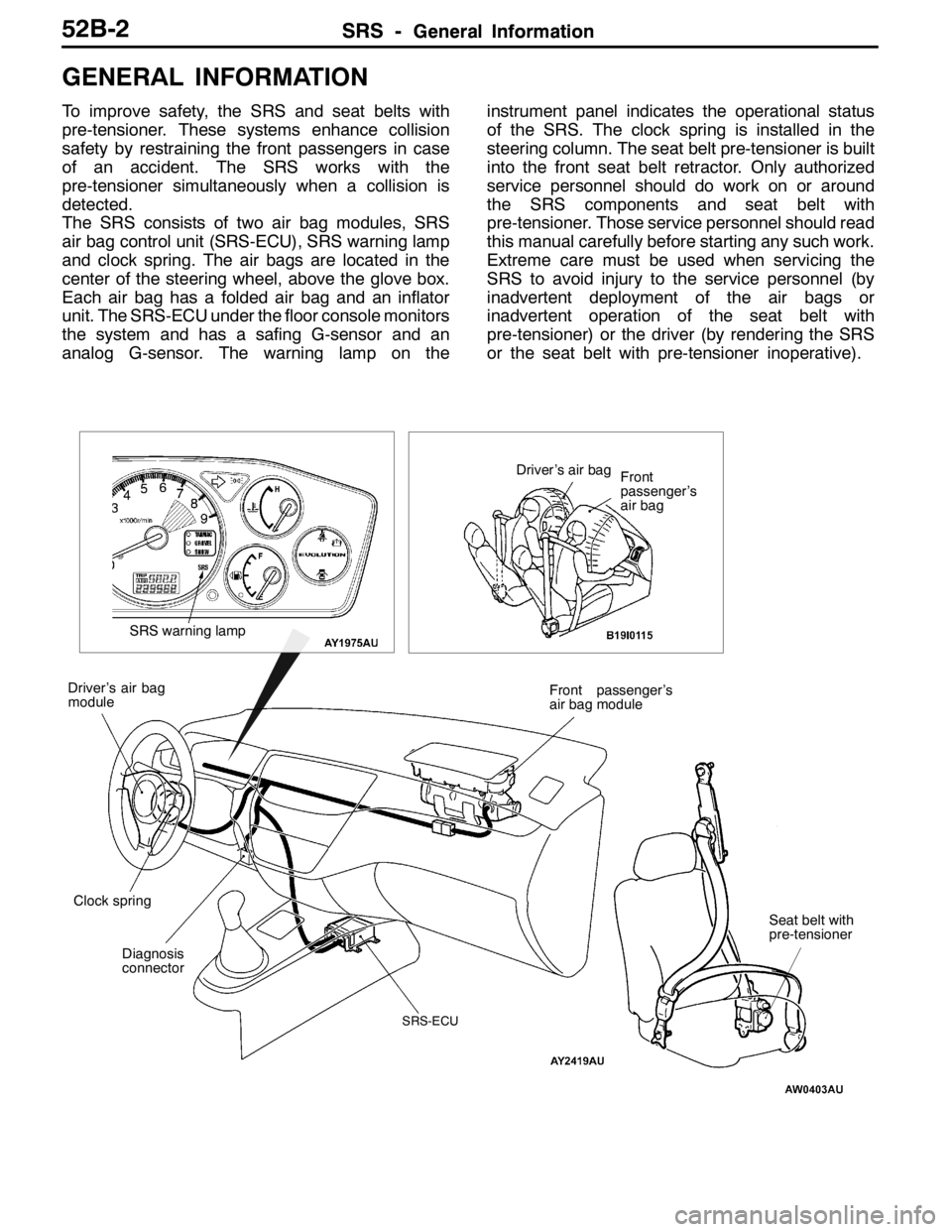
To improve safety, the SRS and seat belts with
pre-tensioner. These systems enhance collision
safety by restraining the front passengers in case
of an accident. The SRS works with the
pre-tensioner simultaneously when a collision is
detected.
The SRS consists of two air bag modules, SRS
air bag control unit (SRS-ECU), SRS warning lamp
and clock spring. The air bags are located in the
center of the steering wheel, above the glove box.
Each air bag has a folded air bag and an inflator
unit. The SRS-ECU under the floor console monitors
the system and has a safing G-sensor and an
analog G-sensor. The warning lamp on theinstrument panel indicates the operational status
of the SRS. The clock spring is installed in the
steering column. The seat belt pre-tensioner is built
into the front seat belt retractor. Only authorized
service personnel should do work on or around
the SRS components and seat belt with
pre-tensioner. Those service personnel should read
this manual carefully before starting any such work.
Extreme care must be used when servicing the
SRS to avoid injury to the service personnel (by
inadvertent deployment of the air bags or
inadvertent operation of the seat belt with
pre-tensioner) or the driver (by rendering the SRS
or the seat belt with pre-tensioner inoperative).
Diagnosis
connectorFront passenger’s
air bag module
Clock spring Driver’s air bag
module
SRS-ECU
SRS warning lamp
Driver’s air bag
Front
passenger’s
air bag
Seat belt with
pre-tensioner
Page 1247 of 1449

SRS -SRS Service Precautions52B-3
SRS SERVICE PRECAUTIONS
1. In order to avoid injury to yourself or others
from accidental deployment of the air bag and
accidental operation of the seat belt with
pre-tensioner during servicing, read and
carefully follow all the precautions and
procedures described in this manual.
2. Do not use any electrical test equipment on
or near SRS components, except those
specified on P.52B-6.
3. Never Attempt to Repair the Following
Components:
DSRS air bag control unit (SRS-ECU)
DClock spring
DDriver’s and front passenger’s air bag
modules
DSeat belt with pre-tensionerNOTE
If any of these components are diagnosed as
faulty, they should only be replaced, in
accordance with the INDIVIDUAL COM-
PONENTS SERVICE procedures in this
manual. (Refer to P.52B-49.)
4. After disconnecting the negative (–) battery cable,
wait 60 seconds at least before any service and
insulate the disconnected cable with tape. The SRS
retain enough voltage to deploy the air bags for a
short time even after the disconnection of the battery.
So, serious injury may result by accidental air bag
deployment if a work is done on the SRS just after
the disconnection of the battery.
5. Do not attempt to repair the wiring harness connectors
of the SRS. If the connector(s) are diagnosed as defective,
replace the wiring harness(es). If the harness(es) are
diagnosed as faulty, replace or repair the wiring
harness(es) according to the table that follows.
Insulating tape
Battery
SRS-ECU connector