lock MITSUBISHI LANCER EVOLUTION 2007 Service Repair Manual
[x] Cancel search | Manufacturer: MITSUBISHI, Model Year: 2007, Model line: LANCER EVOLUTION, Model: MITSUBISHI LANCER EVOLUTION 2007Pages: 1449, PDF Size: 56.82 MB
Page 1298 of 1449

SRS -Air Bag Modules and Clock Spring52B-54
3 2
4
1
50±5 N·m
2
Steering wheel - driver’s air bag
module assembly removal steps
AD"1. Cover
AE"2. Steering wheel - driver’s air bag
module assemblySteering wheel - driver’s air bag
module assembly installation steps
"AADPre-installation inspection
2. Steering wheel - driver’s air bag
module assembly
1. Cover
DNegative ( - ) terminal of the battery
connection
"DADPost-installation inspection
Clock spring removal steps
AD"1. Cover
AE"2. Steering wheel - driver’s air bag
module assembly
3. Lower Column Cover
AC"4. Clock springClock spring installation steps
"AADPre-installation inspection
"BA4. Clock spring
3. Lower Column Cover
"CA2. Steering wheel - driver’s air bag
module assembly
1. Cover
DNegative ( - ) terminal of the battery
connection
"DADPost-installation inspection
Page 1299 of 1449

SRS - Air Bag Modules and Clock Spring52B-55
1
Removal steps
DInstrument panel assembly
(Refer to GROUP 52A - Instrument
panel.)
A
F"1. Passenger’s air bag moduleInstallation steps
"AADPre-installation inspection
1. Passenger’s air bag module
DInstrument panel assembly
(Refer to GROUP 52A - Instrument
panel.)
DNegative ( - ) battery cable connection
"DADPost-installation inspection
REMOVAL SERVICE POINTS
AA"DRIVER’S AIR BAG MODULE REMOVAL
1. Remove the air bag module mounting screw (torque
screw) from the steering wheel side.
2. Spread the lock outward to remove the connector by
prying with a flat-tipped screw driver as shown in the
illustration at left.
Caution
(1) Be careful not to remove the connector forcibly.
(2) Keep the removed driver’s air bag module facing
the pad surface upward in a clean and dry place.
locked
Connector
Flat-tipped screw
driver
locked
Page 1300 of 1449

SRS - Air Bag Modules and Clock Spring52B-56
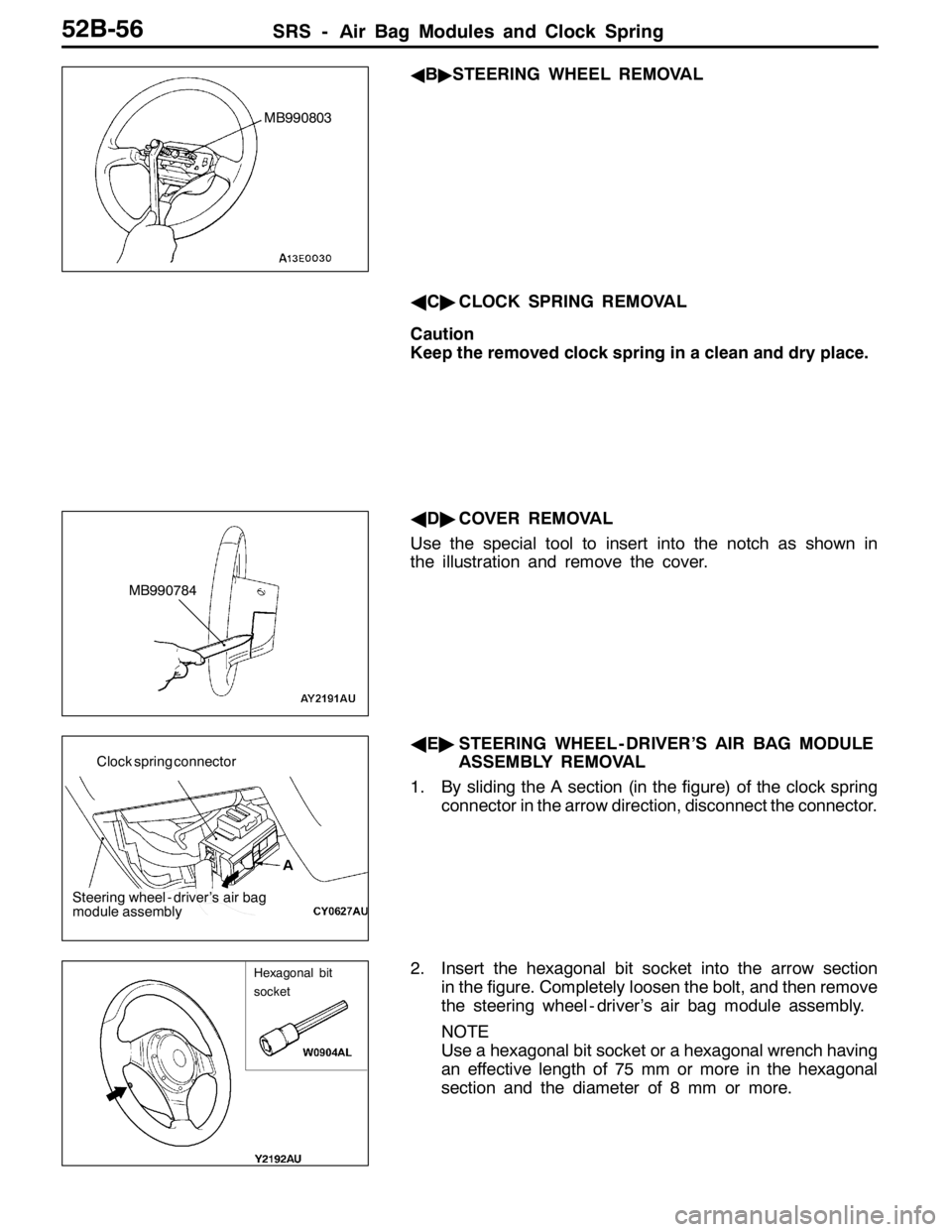
AB"STEERING WHEEL REMOVAL
AC"CLOCK SPRING REMOVAL
Caution
Keep the removed clock spring in a clean and dry place.
AD"COVER REMOVAL
Use the special tool to insert into the notch as shown in
the illustration and remove the cover.
AE"STEERING WHEEL - DRIVER’S AIR BAG MODULE
ASSEMBLY REMOVAL
1. By sliding the A section (in the figure) of the clock spring
connector in the arrow direction, disconnect the connector.
2. Insert the hexagonal bit socket into the arrow section
in the figure. Completely loosen the bolt, and then remove
the steering wheel - driver’s air bag module assembly.
NOTE
Use a hexagonal bit socket or a hexagonal wrench having
an effective length of 75 mm or more in the hexagonal
section and the diameter of 8 mm or more.
MB990803
MB990784
A Clock spring connector
Steering wheel - driver’s air bag
module assembly
Hexagonal bit
socket
Page 1301 of 1449

SRS - Air Bag Modules and Clock Spring52B-57
AF"PASSENGER’S AIR BAG MODULE REMOVAL
Insert the screwdriver ( - ) into the position specified in the
figure and lift the screwdriver upward to release the pawls
engaged, and then remove the passenger’s air bag module.
Caution
1. When the passenger’s air bag module is removed,
do not damage the engagement of the pawls.
2. The removed passenger’s air bag module should be
stored in a clean, dry place with facing the deployment
surface facing up.
INSTALLATION SERVICE POINTS
"AAPRE-INSTALLATION INSPECTION
1. Pre-installation inspection is carried out even if installing
a new air bag module or clock spring. (Refer to P.52B-59.)
Caution
A used air bag module must be discarded after
deoloyment according to the specified procedure.
(Refer to P.52B-64.)
2. Connect the negative ( - ) terminal of the battery.
3. Connect the MUT-II to the diagnosis connector (16 pin).
Caution
Connection and disconnection of the MUT-IImust
be carried out after turning the ignition switch to the
LOCK (OFF) position.
4. Turn the ignition switch to ON.
5. Check that there is no abnormality except for open circuit
in the air bag module after reading diagnostic codes.
6. Turn the ignition switch to LOCK (OFF) position.
7. Release the negative ( - ) terminal cable of the battery
and wrap a tape around it for insulation.
Caution
Wait for at least 60 seconds after disconnecting the
negative ( - ) battery cable before starting any
operation. (Refer to P.52B-3.)
"BACLOCK SPRING INSTALLATION
1. Check that the steering wheel is positioned in the forward
direction.
2. Install the column switch to the clock spring after centering
of the clock spring is carried out as follows.
Centering of the clock spring
After turning the clock spring clockwise fully, turning approximately
3 rounds in the opposite direction, and align mating marks.
Caution
If centering of the clock spring is not properly done, the
SRS air bag system does not function normally due to
possible malfunctions that the steering wheel may not turn
in the way or cables in the clock spring may be torn.
Mating marks
Page 1302 of 1449

SRS - Air Bag Modules and Clock Spring52B-58
"CASTEERING WHEEL/STEERING WHEEL - AIR BAG
MODULE ASSEMBLY INSTALLATION
1. After checking that centering of the clock spring has been
done, install the steering wheel or the steering wheel - air
bag module assembly.
Caution
Do not engage the harness of the clock spring when
installing the steering wheel or the steering wheel - air
bag module assembly.
2. After installation, check that no abnormalities occur when
the steering wheel is fully turned to the left or the right.
"DAPOST-INSTALLATION INSPECTION
1. Check that no abnormal noise or improper operation can
be caused by rotating the steering wheel in left and right
directions slightly.
(driver’s air bag module, clock spring)
2. Turn the ignition switch to the ON position.
3. Check that the SRS warning lamp illuminates for 6 to
8 seconds and goes out.
4. Carry out troubleshooting if the lamp does not go out.
(Refer to P.52-6.)
SRS warning lamp
Page 1303 of 1449

SRS - Air Bag Modules and Clock Spring52B-59
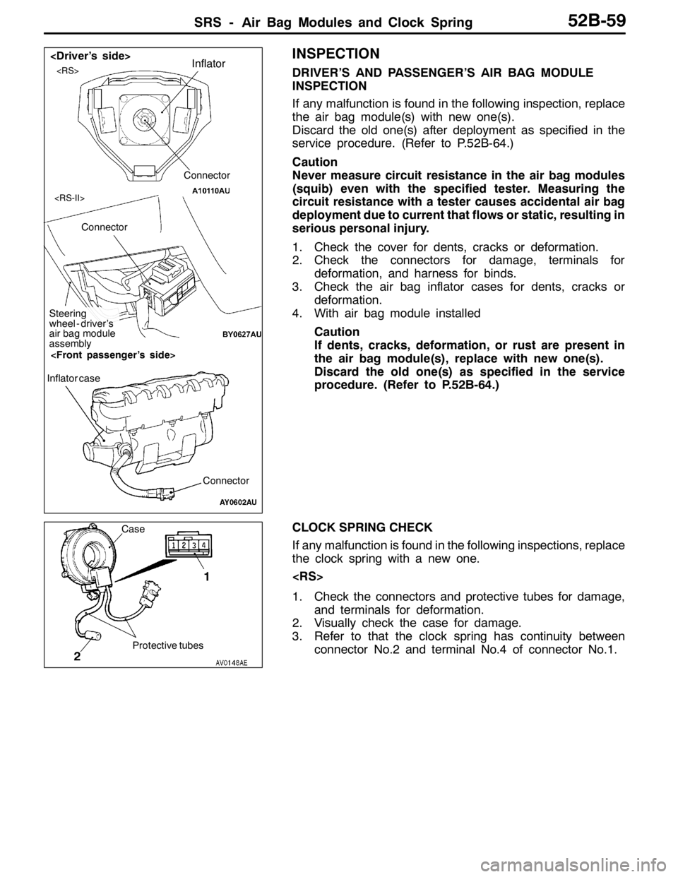
INSPECTION
DRIVER’S AND PASSENGER’S AIR BAG MODULE
INSPECTION
If any malfunction is found in the following inspection, replace
the air bag module(s) with new one(s).
Discard the old one(s) after deployment as specified in the
service procedure. (Refer to P.52B-64.)
Caution
Never measure circuit resistance in the air bag modules
(squib) even with the specified tester. Measuring the
circuit resistance with a tester causes accidental air bag
deployment due to current that flows or static, resulting in
serious personal injury.
1. Check the cover for dents, cracks or deformation.
2. Check the connectors for damage, terminals for
deformation, and harness for binds.
3. Check the air bag inflator cases for dents, cracks or
deformation.
4. With air bag module installed
Caution
If dents, cracks, deformation, or rust are present in
the air bag module(s), replace with new one(s).
Discard the old one(s) as specified in the service
procedure. (Refer to P.52B-64.)
CLOCK SPRING CHECK
If any malfunction is found in the following inspections, replace
the clock spring with a new one.
1. Check the connectors and protective tubes for damage,
and terminals for deformation.
2. Visually check the case for damage.
3. Refer to that the clock spring has continuity between
connector No.2 and terminal No.4 of connector No.1.Inflator
Connector
Connector
Steering
wheel - driver’s
air bag module
assembly
Connector Inflator case
Protective tubes Case
1
2
Page 1304 of 1449

SRS - Air Bag Modules and Clock Spring52B-60
4.Align the paint mark on the connector No.1 of the SRS
check harness (MB991606 or MB991613) with the mark
indicated by an arrow on the connector No.3 of the clock
spring for connector connection.
5.Check that there is continuity between the terminals 22
and 23 of the SRS check harness connector No.2.
1. Check the connectors and protective tubes for damage,
and terminals for deformation.
2. Visually check the case for damage.
3. Refer to that the clock spring has continuity between
connector No.2 and terminal No.4 of connector No.1.
4. Insert the probe (MB991222) from the rear of connector
No.3 of the clock spring.
Caution
The probe must not be inserted directly to the
terminals from the front of the connector.
5. Connect a digital multi-meter to the probe (MB991222),
as shown, to check that conductivity is present between
the terminals.
Clock spring
connector 3 Paint Marking
View A
1
2
3 A
SRS check harness
(MB991613)
Protective tubes Case
1
2
3
Clock springProbe
(MB991222)
3
2
Digital
multi-meter
3
Page 1305 of 1449

SRS -Seat Belt with Pre-tensioner52B-61
SEAT BELT WITH PRE-TENSIONER
Caution:
1. Wait for at least 60 seconds after
disconnecting the negative ( - ) terminal of
the battery before starting any operation.The
removed negative ( - ) terminal must be
protected by wrapping the tape. (Refer to
P.52B-3.)
2. Never disassemble or repair the seat belt
with pre-tensioner. Replace the part with a
new one when it malfunctions.
3. Take an extra care to deal with the seat belt
with pre-tensioner by avoiding dropping or
wetting it with water or oil. If any dent, crack,
or deformation is found, be sure to replace
the seat belt with pre-tensioner with a new
part.4. Do not place a heavy object on top of the
seat belt pre-tensioner.
5. Never keep the seat belt with pre-tensioner
in a place where the temperature can exceed
over 90_C.
6. Replace the seat belt with pre-tensioner with
a new one after operating the seat belt
pre-tensioner.
7. Wear gloves or protective glasses when
handling the seat belt with pre-tensioner
after operation.
8. If the seat belt with pre-tensioner before
operation needs to be discarded, be sure
to do so after operating the seat belt
pre-tensioner. (Refer to P.52B-64.)
REMOVAL AND INSTALLATION
Pre - removal operation
DTurn the ignition key to the LOCK(OFF) position.
DDisconnect the negative ( - ) terminal of the battery.
1 4
3
2
44±10 NSm
44±10 NSm
5
Removal steps
1. Sash cover guide
2. Seat belt lower anchor bolt
3. Bracket
4. Seat belt shoulder anchor bolt
DCenter pillar lower trim
(Refer to GROUP 52A - Trim.)
5. Seat belt pre-tensionerInstallation steps
"AA
DPre - installation inspection
5. Seat belt pre-tensioner
4. Seat belt shoulder anchor bolt
3. Bracket
2. Seat belt lower anchor bolt
DCenter pillar lower trim
(Refer to GROUP 52A - Trim.)
1. Sash cover guide
DNegative ( - ) terminal of the battery
connection
"BADPost - installation inspection
Page 1306 of 1449

SRS -Seat Belt with Pre-tensioner52B-62
INSTALLATION SERVICE POINTS
"AAPRE-INSTALLATION INSPECTION
1. Pre-installation inspection must be carried out even when
installing a new seat belt with pre-tensioner. (Refer to
Inspections.)
Caution
If the seat belt with pre-tensioner is discarded, discard
it after operating the seat belt pre-tensioner according
to the specified procedure. (Refer to P.52B-64.)
2. Connect the negative ( - ) terminal of the battery.
3. Connect the MUT-II to the diagnosis connector (16 pin).
Caution
Connection and disconnection of the MUT-II must be
carried out after turning the ignition switch to the
LOCK (OFF) position.
4. Turn the ignition switch to ON position.
5. Check that there is no abnormality except for open circuit
in the seat belt pre-tensioner after reading diagnostic
codes.
6. Turn the ignition key to LOCK (OFF) position.
7. Release the negative ( - ) terminal cable of the battery
and wrap a tape around it for insulation.
Caution
Wait for at least 60 seconds after disconnecting the
negative ( - ) battery cable before starting any
operation. (Refer to P.52B-3.)
"BAPOST-INSTALLATION INSPECTION
1. Turn the ignition switch to the ON position.
2. Check that the SRS warning lamp illuminates for 6 to
8 seconds and goes out.
3. Carry out troubleshooting if the lamp does not go out.
(Refer to P.52B-6.)
SRS warning lamp
Page 1309 of 1449

SRS -AirBagModuleandSeatBeltPre-tensioner
Disposal Procedures52B-65
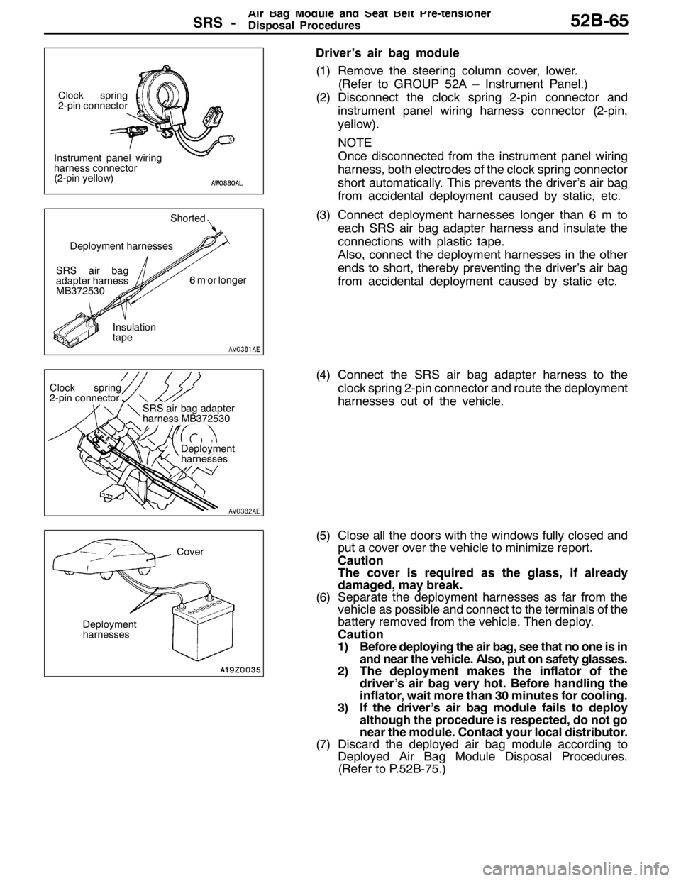
Driver’s air bag module
(1) Remove the steering column cover, lower.
(Refer to GROUP 52A – Instrument Panel.)
(2) Disconnect the clock spring 2-pin connector and
instrument panel wiring harness connector (2-pin,
yellow).
NOTE
Once disconnected from the instrument panel wiring
harness, both electrodes of the clock spring connector
short automatically. This prevents the driver’s air bag
from accidental deployment caused by static, etc.
(3) Connect deployment harnesses longer than 6 m to
each SRS air bag adapter harness and insulate the
connections with plastic tape.
Also, connect the deployment harnesses in the other
ends to short, thereby preventing the driver’s air bag
from accidental deployment caused by static etc.
(4) Connect the SRS air bag adapter harness to the
clock spring 2-pin connector and route the deployment
harnesses out of the vehicle.
(5) Close all the doors with the windows fully closed and
put a cover over the vehicle to minimize report.
Caution
The cover is required as the glass, if already
damaged, may break.
(6) Separate the deployment harnesses as far from the
vehicle as possible and connect to the terminals of the
battery removed from the vehicle. Then deploy.
Caution
1) Before deploying the air bag, see that no one is in
and near the vehicle. Also, put on safety glasses.
2) The deployment makes the inflator of the
driver’s air bag very hot. Before handling the
inflator, wait more than 30 minutes for cooling.
3) If the driver’s air bag module fails to deploy
although the procedure is respected, do not go
near the module. Contact your local distributor.
(7) Discard the deployed air bag module according to
Deployed Air Bag Module Disposal Procedures.
(Refer to P.52B-75.)
Instrument panel wiring
harness connector
(2-pin yellow)Clock spring
2-pin connector
SRS air bag
adapter harness
MB372530Shorted
6 m or longer
Insulation
tape Deployment harnesses
Clock spring
2-pin connector
SRS air bag adapter
harness MB372530
Deployment
harnesses
Cover
Deployment
harnesses