check MITSUBISHI LANCER IX 2006 Service Manual
[x] Cancel search | Manufacturer: MITSUBISHI, Model Year: 2006, Model line: LANCER IX, Model: MITSUBISHI LANCER IX 2006Pages: 800, PDF Size: 45.03 MB
Page 229 of 800
PARKING BRAKE LINING AND DRUM
PARKING BRAKES36-9
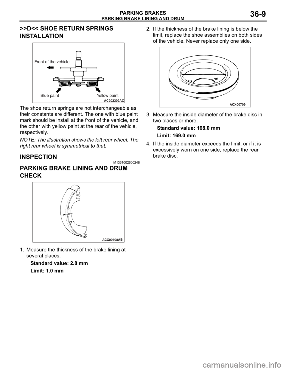
>>D<< SHOE RETURN SPRINGS
INSTALLATION
AC202302AC
Front of the vehicleBlue paint Yellow paint
The shoe ret u rn sp rings are n o t in tercha ngeab le as
their const
a nt s are d i f f e r ent. Th e one with blue p a in t
mark
should be inst a ll at t he fron t o f th e vehicle, and
the oth
e r with yellow p a int a t the re ar of th e ve hicle,
respectively
.
NOTE: The ill ustratio n sh ows th e lef t rear whee l. T he
right re
ar wheel is symme trical to that.
INSPECTION
M13610026 0024 8
PARKING BRAKE LI NING AND DRUM
CHECK
ACX00708AB
1.
Measure the thickne ss of the b r ake lining at
seve ral place s .
St andard va lue: 2.8 mm
Limit: 1.0 mm
2.If the thickness of t he brake linin g is belo w the
limit, rep l ace the shoe a s semblies on bo th sides
o f the vehicle. Ne ver re place only on e side.
ACX00709
3.Measure the inside d i ameter of the bra k e d i sc in
two p l aces o r more .
St andard va lue: 16 8.0 mm
Limit: 169.0 mm
4.If the inside diamete r exceeds the limit, or if it is
e xce ssively worn on one side, rep l ace the re ar
b r ake d i sc.
Page 231 of 800
37-1
GROUP 37
POWER STEERING
CONTENTS
GENERAL INFORMATION . . . . . . . .37-3
SERVICE SPECIFICATIONS . . . . . . .37-6
LUBRICANTS . . . . . . . . . . . . . . . . . .37-7
SEALANTS . . . . . . . . . . . . . . . . . . . .37-7
SPECIAL TOOLS . . . . . . . . . . . . . . . .37-8
ON-VEHICLE SERVICE . . . . . . . . . . .37-11
STEERING WHEEL FREE PLAY CHECK . 37-11
STEERING ANGLE CHECK . . . . . . . . . . . . 37-11
TIE ROD END BALL JOINT TURNING
TORQUE CHECK . . . . . . . . . . . . . . . . . . . . 37-12
STATIONARY STEERING EFFORT
CHECK . . . . . . . . . . . . . . . . . . . . . . . . . . . . 37-12
STEERING WHEEL RETURN TO
CENTRE CHECK . . . . . . . . . . . . . . . . . . . . 37-13
DRIVE BELT TENSION CHECK. . . . . . . . . 37-13
FLUID LEVEL CHECK . . . . . . . . . . . . . . . . 37-13
FLUID REPLACEMENT . . . . . . . . . . . . . . . 37-13
POWER STEERING SYSTEM AIR
BLEEDING . . . . . . . . . . . . . . . . . . . . . . . . . 37-14
OIL PUMP PRESSURE TEST . . . . . . . . . . 37-14
POWER STEERING PRESSURE
SWITCH CHECK . . . . . . . . . . . . . . . . . . . . . 37-15
TIE ROD END BALL JOINT DUST
COVER CHECK . . . . . . . . . . . . . . . . . . . . . 37-15
STEERING COLUMN SHAFT ASSEMBLY
SHOCK ABSORBING MECHANISM
CHECK . . . . . . . . . . . . . . . . . . . . . . . . . . . . 37-15
STEERING WHEEL . . . . . . . . . . . . . .37-17
REMOVAL AND INSTALLATION
REMOVAL AND INSTALLATION
Continued on next page
WARNINGS REGARDING SERVICING OF SUPPLEMENTAL RESTRAINT SYSTEM (SRS) EQUIPPED VEHICLES
WARNING
•Improper service or maintenance of any component of the SRS, or any SRS-related component, can lead to
personal injury or death to service personnel (from inad vertent firing of the air bag) or to the driver and
paassenger (from renderin g the SRS inoperative).
•Service or maintenance of any SRS component or SRS-related component must be performed only at an
authorized MITSUBISHI dealer.
•MITSUBISHI dealer personnel must thoroughly review th is manual, and especially its GROUP 52B - Supplemental
Restraint System (SRS) before begi nning any service or maintenance of any component of the SRS or any
SRS-related component.
NOTE
The SRS includes the following components: SRS air bag control unit, SRS warning light, front impact sensors, air bag module,
clock spring, and interconnecting wiring. Other SRS-related components (that may have to be removed/installed in connection
with SRS service or maintenance) are indicated in the table of contents by an asterisk (*).
Page 233 of 800
GENERAL INFORMATION
POWER STEERING37-3
GENERAL INFORMATION
M1372000100661
Power steering has been adopted in all vehicles to
make the steering system easier to handle.
FEATURES
•A 4-spoke steering wheel is used.
•MOMO leather-wrapped 3-spoke steering wheel
is used.
•A steering column has a shock absorbing mecha-
nism and a tilt steering mechanism.
•Integral-type rack and pinion gear with high rigid-
ity and excellent response is used.
•A vane type pump with a fluid flow rate control
system which change steering effort according to
the engine speed is used.
•The separate plastic resin oil reservoir is used to
reduce weight and to make the fluid level check
-
ing easier.
SPECIFICATIONS
ItemInviteIntense
Steering
wheelTy p e4-spoke typeMOMO leather-wrapped
3-spoke type
Outside diameter mm380365
Maximum number of turns3.193.08
Steering
columnColumn mechanismShock absorbing mechanism and Tilt steering mechanism
Power steering typeIntegral type
Oil pumpTy p eVane pump
Basic discharge amount cm3/rev.7.2 <1300, 1600>
8.1 <2000>
7.2 <1300, 1600>
8.1 <2000>
Relief pressure MPa8.88.8
Reservoir typeSeparate type (plastic)
Pressure switchEquipped
Steering
gearTy p eRack and pinion
Stroke ratio (Rack stroke/Steering
wheel maximum turning radius)45.7445.74
Rack stroke mm146141
Page 241 of 800
ON-VEHICLE SERVICE
POWER STEERING37-11
ON-VEHICLE SERVICE
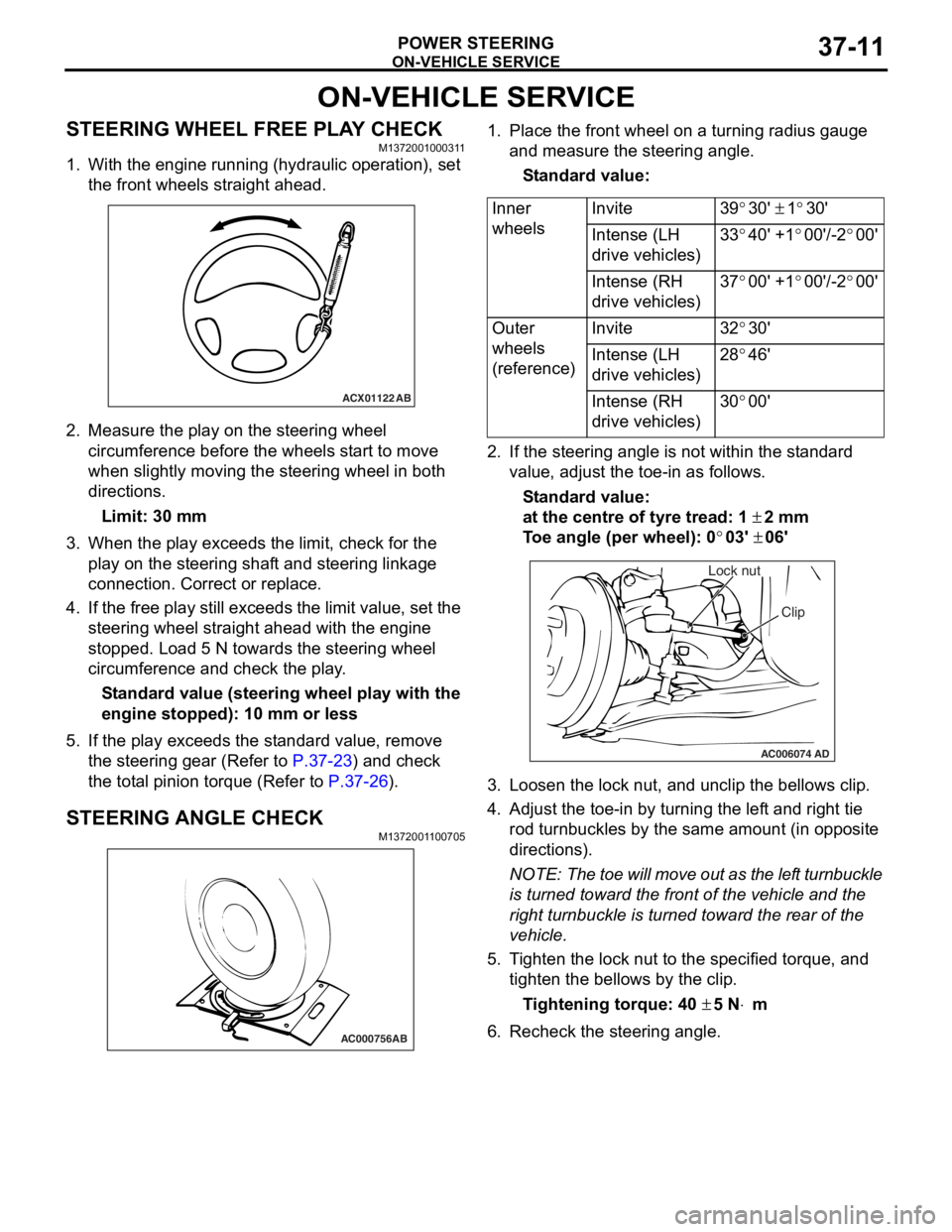
STEERING WHEEL FREE PLAY CHECKM1372001000311
1. With the engine running (hydraulic operation), set the front wheels straight ahead.
ACX01122 AB
2.Measure the play on th e ste e ring wh eel
circumfer ence before the whee ls st a r t to move
when slightly moving the stee ring whe e l in both
direct ions.
Limit: 30 mm
3.Wh en the play exceed s the limit, check fo r the
play on the stee ring shaf t and stee ring linkage
connectio n . Correct or replace .
4.If th e free play still exceeds the limit valu e, set t he
steering wheel stra ight ahead with the engine
stoppe d. Loa d 5 N towards the steer ing whee l
circumfer ence and check the play .
St andard value (steering whee l pla y with the
engine s
t opped): 1 0 mm o r l ess
5.If the play e xce eds the st an dard value , remove
th e ste e ring gear (Refe r to
P.37-23) and check
the tot a l p i nion torqu e (Refer to P.37-26).
STEERING ANGLE CHECKM137200 1 1 0070 5
AC000756AB
1.Place t he fron t wh eel on a tu rning radiu s gau ge
a nd me asure the steering ang le.
St andard va lue:
Inner
wheelsInvite39°30' ± 1°30'
Intense (LH
drive vehicles)33°40' +1°00'/-2°00'
Intense (RH
drive vehicles)37°00' +1°00'/-2°00'
Outer
wheels
(reference)Invite32°30'
Intense (LH
drive vehicles)28°46'
Intense (RH
drive vehicles)30°00'
2.If the steerin g ang le is not within the st a ndard
value , adjust t he toe-in as follows.
St andard va lue:
at the centre of tyre trea d: 1 ± 2 mm
To e angle (p er whee l): 0°03' ± 06'
AC006074 AD
Lock nut
Clip
3.L oose n the lock nut, and un clip the bellows clip .
4.Adjust the toe - in by turning th e lef t an d righ t tie
ro d turnb u ckles by th e sa me a m oun t (in o pposite
directions).
NOTE: The to e will move out as th e lef t turnbuckle
is tur
ned toward the fro n t of th e ve hicle an d the
right tu
rnbuckle is turned toward the rear of the
vehicle.
5. T i ghten the lo ck nut to the specified torque , and
tighten the be llo ws by the clip .
Ti ghte n ing torque: 40 ± 5 N⋅m
6.Recheck the stee ring a ngle .
Page 242 of 800
ON-VEHICLE SERVICE
POWER STEERING37-12
TIE ROD END BALL JOINT TURNING
TORQUE CHECK
M1372001500554
CAUTION
•Do not remove the tie rod end nut from the
ball joint. Loosen it and use special tool to
avoid possible damage to the ball joint
threads.
•
AC208247AJ
CordBoltMB991897
or
MB992011
Nut
Ball joint
Hang special tool with cord to prevent it from
falling.
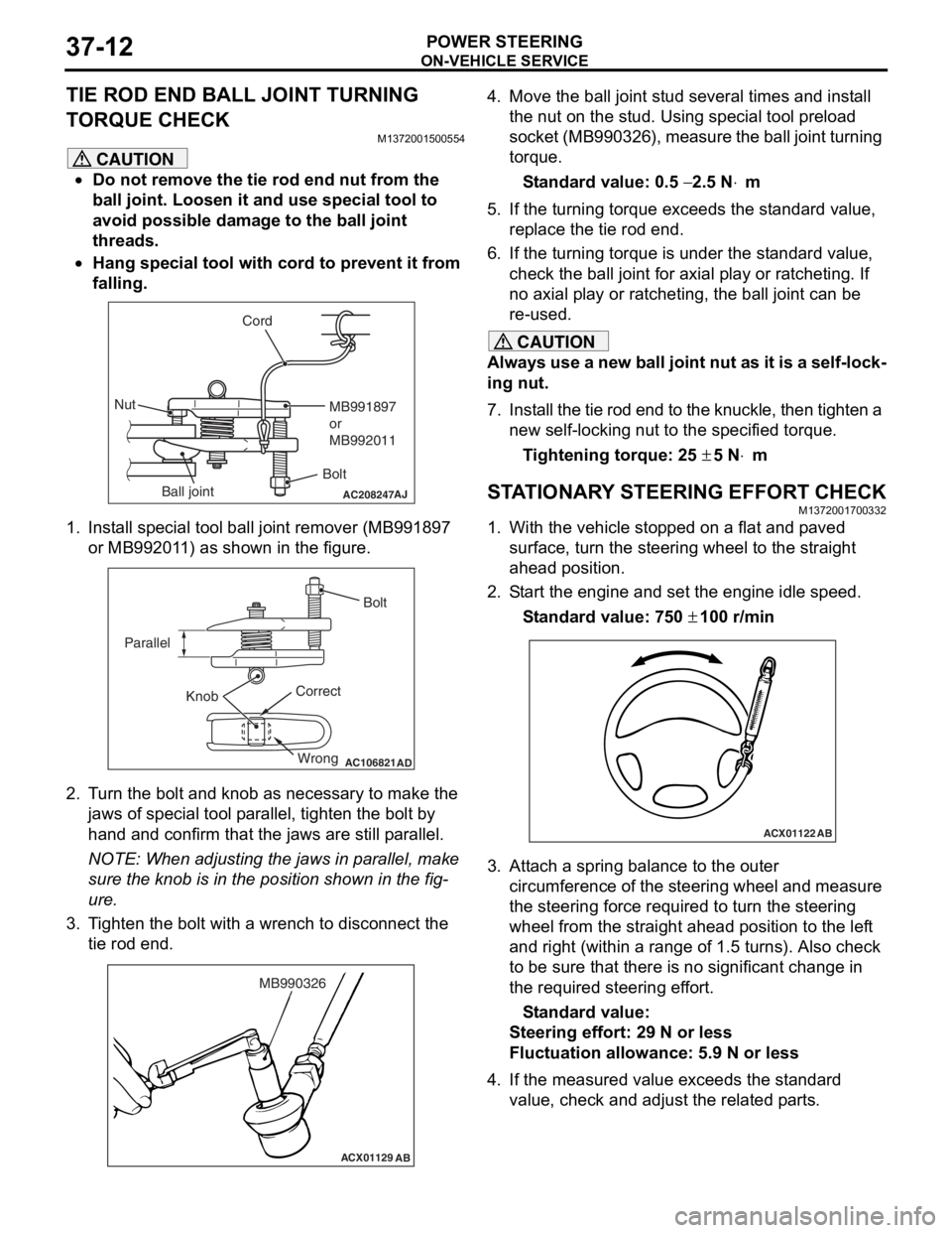
1. Install special tool ball joint remover (MB991897 or MB992011) as shown in the figure.
AC106821
Knob
Parallel
Bolt
Correct Wrong
AD
2. Turn the bolt and knob as necessary to make the jaws of special tool parallel, tighten the bolt by
hand and confirm that the jaws are still parallel.
NOTE: When adjusting the jaws in parallel, make
sure the knob is in the position shown in the fig
-
ure.
3. Tighten the bolt with a wrench to disconnect the tie rod end.
ACX01129 AB
MB990326
4. Move the ball joint stud several times and install
the nut on the stud. Using special tool preload
socket (MB990326), measure the ball joint turning
torque.
Standard value: 0.5 − 2.5 N⋅m
5. If the turning torque exceeds the standard value, replace the tie rod end.
6. If the turning torque is under the standard value, check the ball joint for axial play or ratcheting. If
no axial play or ratcheting, the ball joint can be
re-used.
CAUTION
Always use a new ball joint nut as it is a self-lock-
ing nut.
7. Install the tie rod end to the knuckle, then tighten a new self-locking nut to the specified torque.
Tightening torque: 25 ± 5 N⋅m
STATIONARY STEERING EFFORT CHECKM1372001700332
1. With the vehicle stopped on a flat and paved
surface, turn the steering wheel to the straight
ahead position.
2. Start the engine and set the engine idle speed.
Standard value: 750 ± 100 r/min
ACX01122 AB
3. Attach a spring balance to the outer
circumference of the steering wheel and measure
the steering force required to turn the steering
wheel from the straight ahead position to the left
and right (within a range of 1.5 turns). Also check
to be sure that there is no significant change in
the required steering effort.
Standard value:
Steering effort: 29 N or less
Fluctuation allowance: 5.9 N or less
4. If the measured value exceeds the standard value, check and adjust the related parts.
Page 243 of 800
ON-VEHICLE SERVICE
POWER STEERING37-13
STEERING WHEEL RETURN TO CENTRE
CHECK
M1372001800317
Conduct a road test:
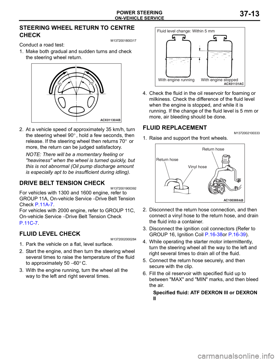
1. Make both gradual and sudden turns and check the steering wheel return.
ACX01130 AB
70˚ 70˚
2.
At a vehicle sp eed of a pproxima t ely 35 km/h, turn
th e ste e ring wh eel 9 0
°, ho ld a few se cond s, the n
release. If th
e ste
e
ring
wh eel t hen ret u rns 7 0
° or
more, th
e return
can
be ju
dged satisfactory
.
NOTE: There will be a mome nt a r y fee lin g or
"he
a
viness" when t he wheel is turned quickly , but
th
is is n o t abno rmal (Oil pu mp discharge amou nt
is especially a p t to b e insufficie n t during id lin g).
DRIVE BELT TENSION CHECK
M13720019 0039 2
For vehicles with 13 00 and 1600 engin e , refer to
GROUP 1
1 A, On-vehicle Service
− Drive Belt T ension
Che
c
k
P.11A-7.
For veh i cles wit h 2000 e ngin e , refer to GROUP 1 1 C,
On-vehicle Se
rvice
− Drive Belt Te nsion Check
P.1 1 C - 7.
FLUID LEVEL CHECK
M13720020 0028 4
1.Park the vehicle on a f l at, leve l su rface .
2.S t art the engine, and t hen tu rn the ste e ring wheel
seve ral times to raise the temperat ure of th e flu i d
to approximately 50
− 60°C.
3.With the engine run n ing, turn the wheel all the
way to the lef t an d righ t several times.
ACX01131With engine running With engine stoppedAC
Fluid level change: Within 5 mm
4.Check t he flu i d in the oil r e servoir f o r foaming or
milkine s s. Check the d i f f e r ence of the fluid le vel
when the e ngine is stop ped, an d while it is
ru nning . If the chan ge of th e fluid le vel is 5 mm or
more, a i r bleedin g sh ould be don e.
FLUID REPLACEMENT
M13720021 0033 3
1.Raise a nd su pport t he fron t wheels.
AC100369AB
Return hoseReturn hose
Vinyl hose
2. Disco nnect the re turn hose connection , and then
conne ct a vinyl hose to the re turn h o se, and drain
th e flu i d into a cont ain e r .
3.Disco nnect the ignition coil con necto rs (Refe r to
GROUP 16, Ignition Coil
P.16-38or P.16-39).
4.Wh ile operat ing th e st arter moto r inter m itt ently ,
tu rn the steering whee l all the wa y to t he le f t a nd
right seve ral times to dra i n all of the fluid.
5.Conn ect the retu rn hose se curely , and then
secu re with t he clip.
6.Fill the oil reservo i r with specified fluid u p to
b e tween "MAX" and "MIN" marks, and then bleed
th e air .
Specified fluid: A TF DEXRON III or DEXRON
II
Page 244 of 800
ON-VEHICLE SERVICE
POWER STEERING37-14
POWER STEERING SYSTEM AIR
BLEEDING
M1372002200330
Perform air bleeding procedure as necessary after
replacing the steering gear or the steering fluid lines.
1. Raise and support the front wheels.
2. Disconnect the ignition coil connectors (Refer to GROUP 16, Ignition Coil
P.16-38 or P.16-39).
CAUTION
Perform air bleeding only while cranking the
engine. If air bleeding is performed while the
engine is running, air could enter the fluid. Dur
-
ing air bleeding, refill the steering fluid supply so
that the level never falls below the "MIN" mark on
the oil reservoir.
3. Turn the steering wheel all the way to the left and
right five or six times wh ile using the starter motor
to crank the engine intermittently several times
(for 15 to 20 seconds).
4. Connect the ignition coil connectors (Refer to GROUP 16, Ignition Coil
P.16-38 or P.16-39).
5. Start the engine (idling).
6. Turn the steering wheel to the left and right until there are no air bubbles in the oil reservoir.
7. Confirm that the fluid is not milky, and that the level is between "MAX" and "MIN" marks.
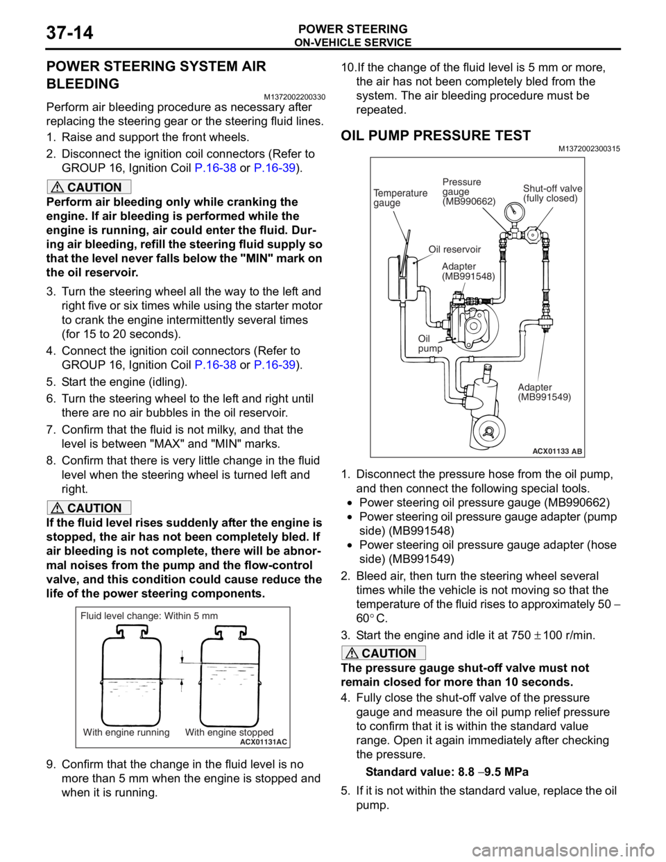
8. Confirm that there is very little change in the fluid
level when the steering wheel is turned left and
right.
CAUTION
If the fluid level rises suddenly after the engine is
stopped, the air has not been completely bled. If
air bleeding is not complete, there will be abnor
-
mal noises from the pump and the flow-control
valve, and this condition could cause reduce the
life of the power steering components.
ACX01131With engine running With engine stoppedAC
Fluid level change: Within 5 mm
9. Confirm that the change in the fluid level is no more than 5 mm when the engine is stopped and
when it is running.
10.If the change of the fluid level is 5 mm or more,
the air has not been completely bled from the
system. The air bleeding procedure must be
repeated.
OIL PUMP PRESSURE TEST
M1372002300315
ACX01133
Temperature
gauge
Oil reservoir
Adapter
(MB991548)
Oil
pump Adapter
(MB991549)
AB
Shut-off valve
(fully closed)
Pressure
gauge
(MB990662)
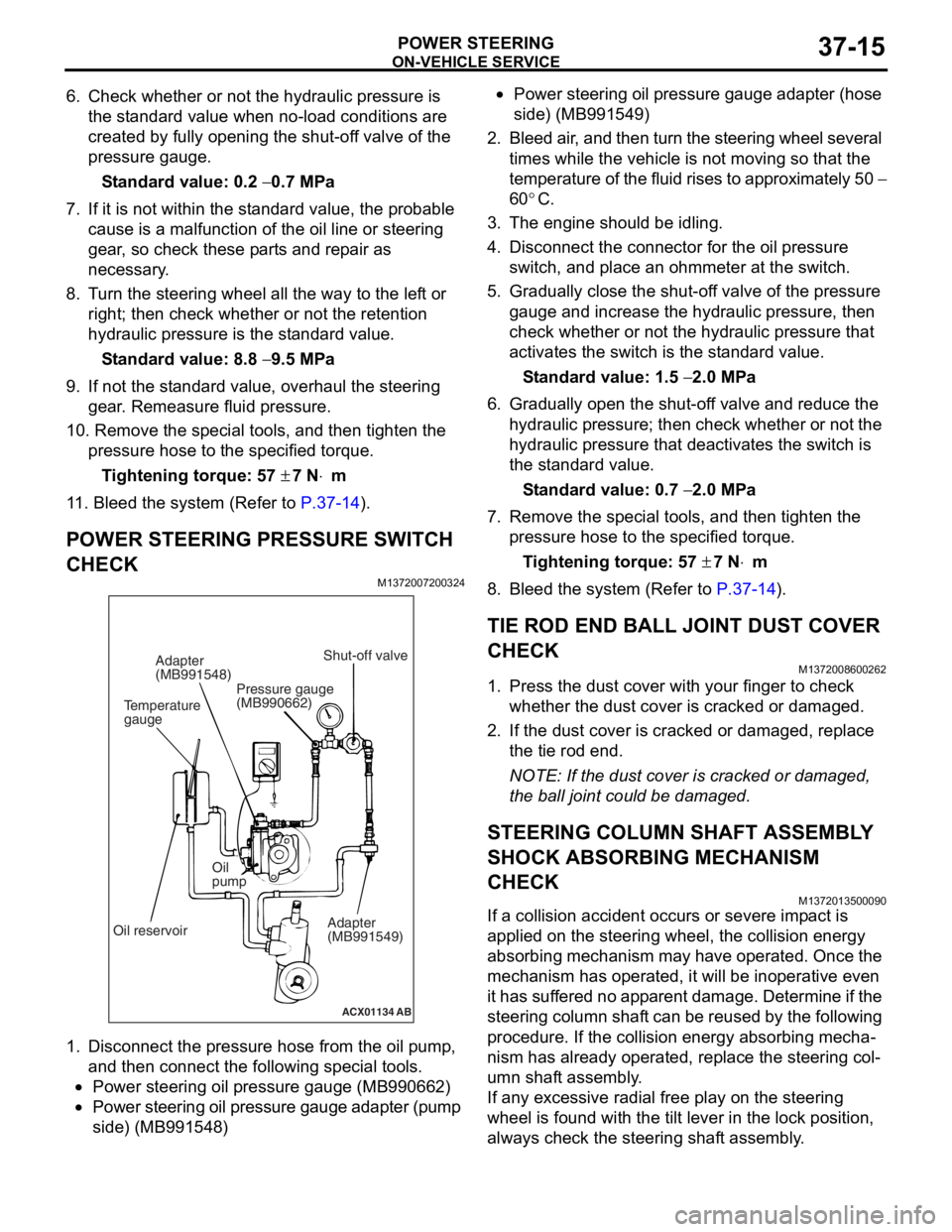
1. Disconnect the pressure hose from the oil pump,
and then connect the following special tools.
•Power steering oil pressure gauge (MB990662)
•Power steering oil pressure gauge adapter (pump
side) (MB991548)
•Power steering oil pressure gauge adapter (hose
side) (MB991549)
2. Bleed air, then turn the steering wheel several times while the vehicle is not moving so that the
temperature of the fluid rises to approximately 50
−
60
°C.
3. Start the engine and idle it at 750 ± 100 r/min.
CAUTION
The pressure gauge shut-off valve must not
remain closed for more than 10 seconds.
4. Fully close the shut-off valve of the pressure gauge and measure the oil pump relief pressure
to confirm that it is within the standard value
range. Open it again immediately after checking
the pressure.
Standard value: 8.8 − 9.5 MPa
5. If it is not within the standard value, replace the oil pump.
Page 245 of 800
ON-VEHICLE SERVICE
POWER STEERING37-15
6. Check whether or not the hydraulic pressure is the standard value when no-load conditions are
created by fully opening the shut-off valve of the
pressure gauge.
Standard value: 0.2 − 0.7 MPa
7. If it is not within the standard value, the probable cause is a malfunction of the oil line or steering
gear, so check these parts and repair as
necessary.
8. Turn the steering wheel all the way to the left or right; then check whether or not the retention
hydraulic pressure is the standard value.
Standard value: 8.8 − 9.5 MPa
9. If not the standard value, overhaul the steering gear. Remeasure fluid pressure.
10. Remove the special tools, and then tighten the
pressure hose to the specified torque.
Tightening torque: 57 ± 7 N⋅m
11. Bleed the system (Refer to P.37-14).
POWER STEERING PRESSURE SWITCH
CHECK
M1372007200324
ACX01134 AB
Temperature
gaugeAdapter
(MB991548)
Oil reservoir Oil
pump
Adapter
(MB991549)
Shut-off valve
Pressure gauge
(MB990662)
1. Disco nnect the pre s sure hose from the oil pump ,
an d then con nect the followin g sp ecial too l s.
•Power steering oil pressure gauge (MB990 662)
•Power steering oil pressure gauge ad apter (pump
side) (MB99154
8)
•Power steering oil pressure gaug e a dapte r (ho s e
side) (MB99154
9)
2. Bleed air , and the n turn t he steering wheel several
times while the vehicle is not moving so that the
tempe r atu r e o f th e flu i d rise s to approximately 50
−
60
°C.
3. Th e engine should be idling.
4.Disco nnect the conne ctor fo r the o il pr essure
switch , and p l ace an o h mmeter a t the switch .
5.Gradua lly close the shut-of f valve of the pressure
g auge a nd in crease the hyd r aulic pre ssu re, the n
check wheth e r or no t the h y drau lic pressure that
a c tivates the switch is the st a ndard valu e.
St andard va lue: 1.5 − 2.0 MPa
6.Gradua lly open the shut-of f va lve and re duce the
h y drau lic p r essure; then check whethe r o r n o t the
h y drau lic pressure that de activate s the switch is
th e st and ard va lue.
St andard va lue: 0.7 − 2.0 MPa
7.Remove the special tools, and then tighten the
p r essure hose to the specified torque .
Ti ghte n ing torque: 57 ± 7 N⋅m
8.Bleed the system (Refer to P.37-14).
TIE ROD END BALL JOINT DUST COVER
CHECK
M13720086 0026 2
1.Press th e dust co ver wit h you r fing er to check
whet her the dust cover is cra cke d or da mage d.
2.If the du st cover is cracked o r damaged, repla c e
th e tie rod end .
NOTE: If the dust cover is cra cke d or da mag ed,
th
e ball jo int could be da mage d.
STEERING COLUMN SHAFT ASSEMBL Y
SHOCK ABSORBING MECHANISM
CHECK
M13720135 0009 0
If a collision accid ent occu rs or seve re imp a ct is
applied on
the steering w heel, the collision energy
abso
r bing mechanism ma y h a ve opera t ed. Once the
mechanism
has o perate d , it will b e ino perative e v en
it has
suf f er ed no app a r en t d a mage . De termin e if the
steering colu
mn shaf t can b e reused b y th e following
proce
dure. If the collision en ergy a b sor b ing mecha
-
nism has already operated, rep l ace the steering col-
umn shaft assembly .
If any excessive radial fre e pla y on the steering
wh
eel is fo und with the tilt lever in the lock po sit i on,
always ch
eck the steering shaf t assembly .
Page 247 of 800
STEERING WHEEL
POWER STEERING37-17
STEERING WHEEL
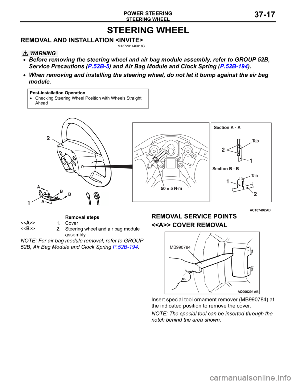
REMOVAL AND INSTALLATION
WARNING
•Before removing the steering wheel and air bag module assembly, refer to GROUP 52B,
Service Precautions (
P.52B-5) and Air Bag Module and Clock Spring (P.52B-194).
•
Post-installation Operation
•Checking Steering Wheel Position with Wheels Straight
Ahead
AC107402AB
50 ± 5 N·m
1
2
21
1 2
A
A B
B Ta b
Ta b
Section A - A
Section B - B
Removal steps
<>1.Cover
<>2.Steering wheel and air bag module
assembly
When removing and installing the steering whee l, do not let it bump against the air bag
module.
NOTE: For air bag module removal, refer to GROUP
52B, Air Bag Module and Clock Spring
P.52B-194.
REMOVAL SERVICE POINTS
<> COVER REMOVAL
AC006294 AB
MB990784
Insert special tool ornament remover (MB990784) at
the indicated position to remove the cover.
NOTE: The special tool can be inserted through the
notch behind the area shown.
Page 248 of 800
STEERING WHEEL
POWER STEERING37-18
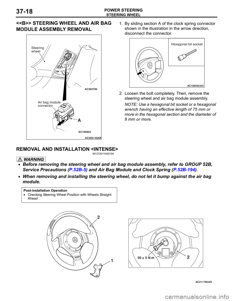
<> STEERING WHEEL AND AIR BAG
MODULE ASSEMBLY REMOVAL
AC105823
AC304700
AC305145AB
A
Steering
wheel
Air bag module
connector
1.By slidin g se ctio n A of the clock spring connector
shown in the illu strat i on in the arrow dire ctio n,
d i sconne ct the con necto r .
AC100442
Hexagonal bit socket
AC
2.L oose n the b o lt comp letely . Then , remo ve th e
steering wheel and air ba g mo dule assembly .
NOTE: Use a hexagon al b i t socket o r a h e xag onal
wren
ch ha vin g an e ffective lengt h of 75 mm or
mo
re in the hexagonal section and t he diameter of
8
mm
or mo re.
REMOV A L AND INST ALLA TION
M137201 14 0019 4
WARNING
•Before removing the steering wheel and air bag module assembly, refer to GROUP 52B,
Service Precautions (
P.52B-5) and Air Bag Module and Clock Spring (P.52B-194).
•
Post-installation Operation
•Checking Steering Wheel Position with Wheels Straight
Ahead
AC211760 AD
50 ± 5 N·m2
1
2
When removing and installing the steering whee
l, do not let it bump against the air bag
module.