check MITSUBISHI LANCER IX 2006 Service Manual
[x] Cancel search | Manufacturer: MITSUBISHI, Model Year: 2006, Model line: LANCER IX, Model: MITSUBISHI LANCER IX 2006Pages: 800, PDF Size: 45.03 MB
Page 311 of 800
DOOR
BODY42-39
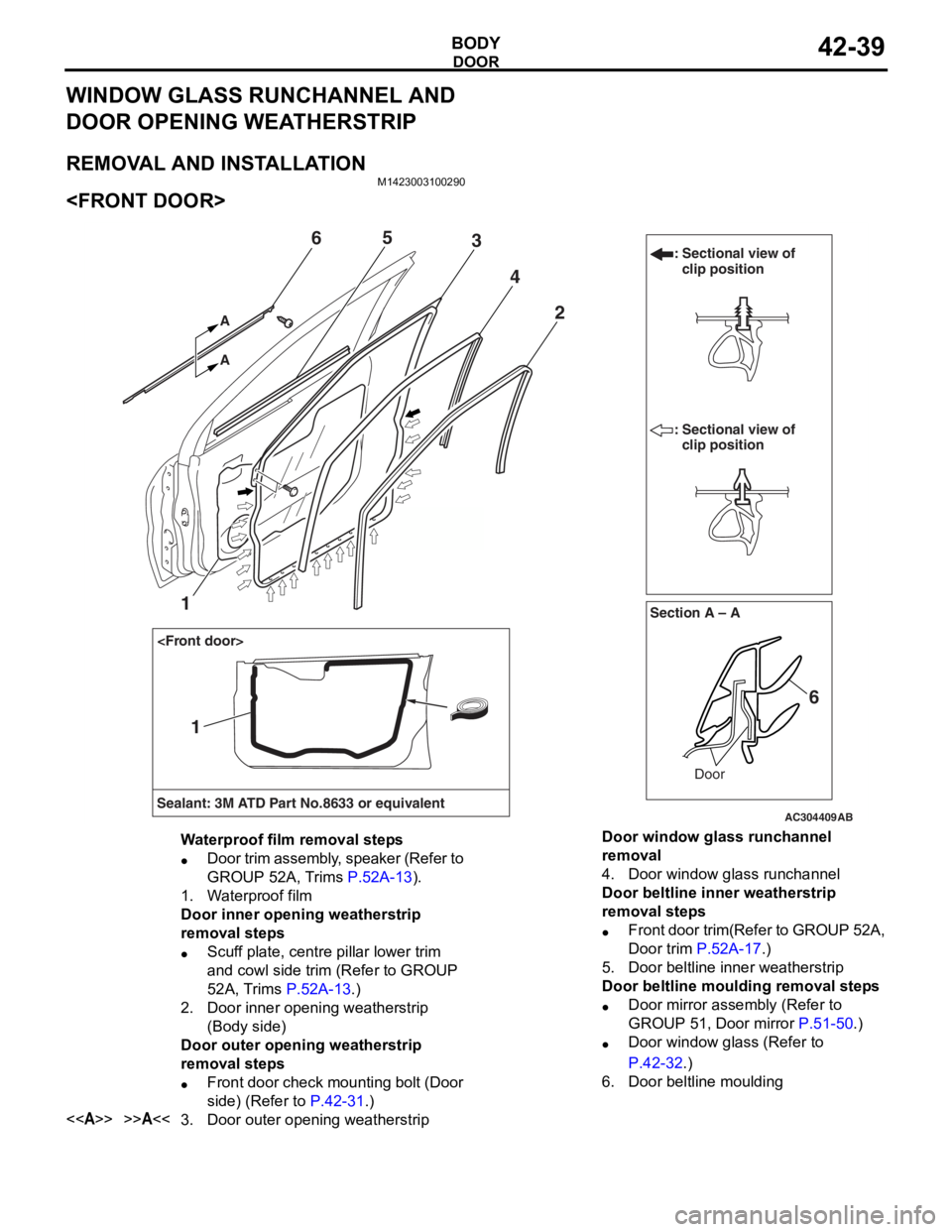
WINDOW GLASS RUNCHANNEL AND
DOOR OPENING WEATHERSTRIP
REMOVAL AND INSTALLATION
M1423003100290
AC304409AB
Section A – A
Sealant: 3M ATD Part No.8633 or equivalent Door
: Sectional view of
clip position
: Sectional view of clip position
6
2
1
4
365
A A
1
Waterproof film removal steps
•Door trim assembly, speaker (Refer to
GROUP 52A, Trims
P.52A-13).
1.Waterproof film
Door inner opening weatherstrip
removal steps
•Scuff plate, centre pillar lower trim
and cowl side trim (Refer to GROUP
52A, Trims
P.52A-13.)
2.Door inner opening weatherstrip
(Body side)
Door outer opening weatherstrip
removal steps
•Front door check mounting bolt (Door
side) (Refer to
P.42-31.)
<>>>A<<3.Door outer opening weatherstrip
Door window glass runchannel
removal
4.Door window glass runchannel
Door beltline inner weatherstrip
removal steps
•Front door trim(Refer to GROUP 52A,
Door trim
P.52A-17.)
5.Door beltline inner weatherstrip
Door beltline moulding removal steps
•Door mirror assembly (Refer to
GROUP 51, Door mirror
P.51-50.)
•Door window glass (Refer to
P.42-32.)
6.Door beltline moulding
Page 312 of 800

DOOR
BODY42-40
AC304418AB
Section A – ADoor
: Sectional view of clip position
: Sectional view of clip position
7
2
4
5
7
A A
3
Section B – B
Door
4
3
6
BB
Sealant: 3M ATD Part No.8633 or equivalent
1
1
Waterproof film removal steps
•Door trim assembly (Refer to GROUP
52A, Door trim
P.52A-17).
1.Waterproof film
Door inner opening weatherstrip
removal steps
•Scuff plate, centre pillar lower trim
and cowl side trim (Refer to GROUP
52A, Trims
P.52A-13.)
2.Door inner opening weatherstrip
(Body side)
Door outer opening weatherstrip
removal steps
•Rear door check mounting bolt (Door
side) (Refer to
P.42-31.)
3.Retainer weatherstrip
<>>>A<<4.Door outer opening weatherstrip
Door window glass runchannel
removal
5.Door window glass runchannel
Door beltline inner weatherstrip
removal steps
•Rear door trim (Refer to GROUP 52A,
Door trim
P.52A-17.)
•Centre sash upper (Refer to P.42-32.)
6.Door beltline inner weatherstrip
Door beltline moulding removal steps
•Door window glass (Refer to
P.42-32.)
•Stationary glass (Refer to P.42-32.)
7.Door beltline moulding
Page 314 of 800
TRUNK LID
BODY42-42
3. If there is a difference in height between the side outer panels and the side edges of the trunk lid
panel assembly, check the trunk lid hinges and, if
necessary, replace them
4. If the clearance around the trunk lid panel assembly is not uniform, and the trunk lid can be
locked and unlocked smoothly, make adjustments
to the trunk lid bumpers (refer to
P.42-42) and
trunk lid hinges (Refer to P.42-42).
5. If the locking and unlocking of the trunk lid still is difficult after making the above adjustments,
adjust the trunk lid striker (Refer to
P.42-42).
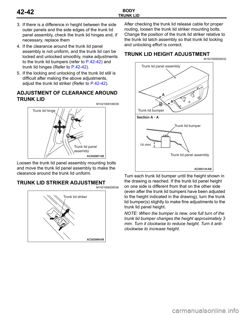
ADJUSTMENT OF CLEARANCE AROUND
TRUNK LID
M1421008100039
AC202897
Trunk lid panel
assembly
Trunk lid hinge
AB
Loosen the trunk lid p a nel a sse mbly mounting bolt s
and move
the trun k lid p anel assembly to make t he
clea
rance aroun d the t r unk lid u n iform.
TRUNK LID STRIKER ADJUSTMENT
M14210082 0003 6
AC202898
Trunk lid striker
AB
After checking the trunk lid relea s e cable for pro per
routin
g, lo osen the trun k lid striker mo untin g bolt s .
Ch
ange th e position of t he trunk lid st rike r relat i ve to
the trun
k lid la tch a s sembly so tha t trunk lid lockin g
and un
lockin g ef f o rt is corre ct.
TRUNK LID HEIGHT ADJUSTMENT
M14210083 0003 3
AC305144
Section A - A
Trunk lid bumper
Trunk lid panel assembly
A
A
Trunk lid bumper Trunk lid panel assembly
AB
14 mm
T
u rn each trun k lid bumper u n til the he ight shown in
the dra
w ing is reached. If the t r unk lid p a n e l he ight
on one
sid e is dif f erent from that on the oth e r side
(even
a f t e r th e t r un k lid bu mp ers have be en ad ju st ed
to the h
e igh t ind i ca ted in the dra w ing), tu rn the trunk
lid bumper(s)
slight ly to make fine adjustment s to the
trunk lid p
a nel h e ight .
NOTE: Whe n the b u mpe r is new , one full turn o f the
trunk lid bumper ch anges t he height appro x imately 3
mm.
T
u
rn it clockwise to r educe height. T u rn it anti
-
clockwise to increase height.
Page 317 of 800

TRUNK LID
BODY42-45
CAUTION
Install the trunk lid torsion bar
trunk lid torsion bar
reversed, the trunk lid torsion bar
be able to be installed because the special tool
will interfere with the trunk lid torsion bar
during installation of the trunk lid torsion bar
1. Identify the LH and RH torsion bars by the colour mark made at the centre of each torsion bar.
Trunk lid torsion barMark
colour
LHVehicles with rear spoilerGreen
Vehicles without rear spoilerWhite
green
RHVehicles with rear spoilerYe l l o w
Vehicles without rear spoilerRed
2. Insert the left end of the trunk lid torsion bar
3. Press portion A of the trunk lid torsion bar
right end against point A on the trunk lid hinge
4. Twist the portion B of the trunk lid torsion bar
moved from point B and pressed against point C
of the trunk lid hinge
Then force the portion into point D.
5. Twist the portion A of the trunk lid torsion bar
lid hinge
6. Attach the trunk lid torsion bar
trunk lid torsion bar
>>B<< TRUNK LID WEATHERSTRIP
INSTALLATION
AC006104AB
Joint
section
Marking
section
Install the trunk lid weatherstrip so that the marking
and the joint are aligned with the body centre line,
INSPECTION
M1421004800133
TRUNK LID LATCH SWITCH CONTINUITY
CHECK
AC305142AB
Trunk lid latch assembly
Switch positionTester
connectionSpecified
condition
ON (Latch open)1 − Earth Less than 2
ohms
OFF (Latch shut)Open circuit
Page 318 of 800

TAILGATE
BODY42-46
TA I L G AT E
SERVICE SPECIFICATIONSM1421000300288
ItemStandard value
Tailgate handle play (mm)2.3 − 5.9
SEALANTS
M1424000500098
ItemSpecified sealant
Tailgate waterproof film3M ATD Part No.8633 or equivalent
Tailgate hinge3M ATD Part No.8531 Heavy drip check sealer, 3M
ATD Part No.8646 Automotive joint and seam sealer
or equivalent
SPECIAL TOOLM1424000600170
ToolNumberNameUse
MB991223
A
D C
B
AZ
DO NOT USE
MB991223
A: MB9912 19
B: MB991220
C: MB99122 1
D: MB991222
Harness set
A: Te st harn e ss
B: LED harness
C: LED harness
adapt er
D: Probe
Te rminal volt a ge measu r emen t
A: For che cking connector pin
cont act pressure
B: For che cking po we r sup p ly
circuit
C: Fo r checking po we r supp ly
circuit
D: Fo r conn ecting a loca lly
sourced tester
MB992006
MB992 006Extra fine probeCont inuity check an d vo lt age
measurement at
harness wire or
conn
ector
Page 319 of 800

TAILGATE
BODY42-47
TROUBLESHOOTING
M1424000700207
The tailgate system is controlled by the Smart Wiring
System (SWS). For troubleshooting, refer to GROUP
54B, Troubleshooting
P.54B-15 or GROUP 54C,
Troubleshooting P.54C-4.
ON-VEHICLE SERVICE
TAILGATE FIT ADJUSTMENTM1424000900137
1. If the striker and latch mesh badly, replace the striker and striker installation blots with
replacement parts (striker: MR523105, striker
installation blot: MU000474).
AC203659
2.Move the rep l aced strike r forward a nd backward
or to the lef t and right to adjust, af te r bolt the
striker temporarily .
3.Af ter ad justing, tighte n the bolt s t o the specifie d
to rque [2 4
± 4 N⋅m].
NOTE:
AC203660AB
Grind here
When the bolt head interfe r es wit h the re ar end
trim, ra
sp th e int e rference are a with a round file .
AC201556
4.If uneven clearan ce is pre s en t between t a ilga te
a nd bod y , reposition the hing e to ad just the
clear ance .
TA ILGA TE HANDLE PLA Y CHECKM14240024 0013 8
AC103270
A
A Section A – A
RodHolder
B
AC
1. Check t he t a ilgate h andle play .
St andard va lue (B): 2.3 − 5.9 mm
2.If it de via t es fro m the st anda rd va lue, r e move the
lower t a ilgate trim (Refe r to GROUP 52A, t a ilgate
trim
P.52A-21) and waterproo f film (Refer to
P.42-48).
3.Remove the ho lder f r om th e t a ilg ate ha ndle and
a d just according to the t a ilgate latch rod an d
t a ilgate handle co nnection position .
Page 321 of 800
AC305322
Adhesive: 3M ATD Part No.8531 Heavy drip check sealer, 3M ATD Part No.8646 Automotive joint and seam sealer
or equivalent
AB
7
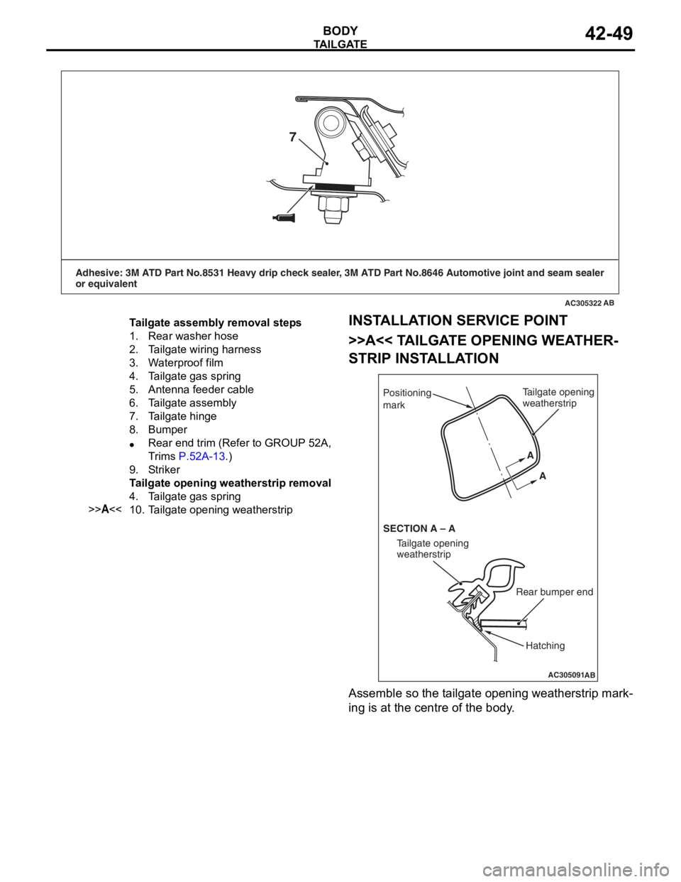
Tailgate assembly removal steps
1.Rear washer hose
2.Tailgate wiring harness
3.Waterproof film
4.Tailgate gas spring
5.Antenna feeder cable
6.Tailgate assembly
7.Tailgate hinge
8.Bumper
•Rear end trim (Refer to GROUP 52A,
Trims
P.52A-13.)
9.Strik er
Tailgate opening weatherstrip removal
4.Tailgate gas spring
>>A<<10.Tailgate opening weatherstrip
TA ILGA TE
BOD Y42-49
INSTALLA T ION SER VICE POINT
>>A<< TA ILGA TE OPENING WEA T HER-
STRIP INSTALLA TION
AC305091
Positioning
mark
AB
Tailgate opening
weatherstrip
Rear bumper end
Tailgate opening
weatherstrip
SECTION A – A A
A
Hatching
Assemble so the t a ilgate o penin g weathe rstrip mark-
ing is at the centre o f the b ody .
Page 322 of 800
TAILGATE
BODY42-50
TAILGATE HANDLE AND LATCH
REMOVAL AND INSTALLATION
M1424001700170
Pre-removal Operation
•Tailgate Handle Play Check (Refer to P.42-47).
Y1518AU
Y1520AU
AC305141
4 5
6
3
3 5
5.0 ± 1.0 N·m
9.0 ± 2.0 N·m
AB
2
1
22 ± 4 N·m
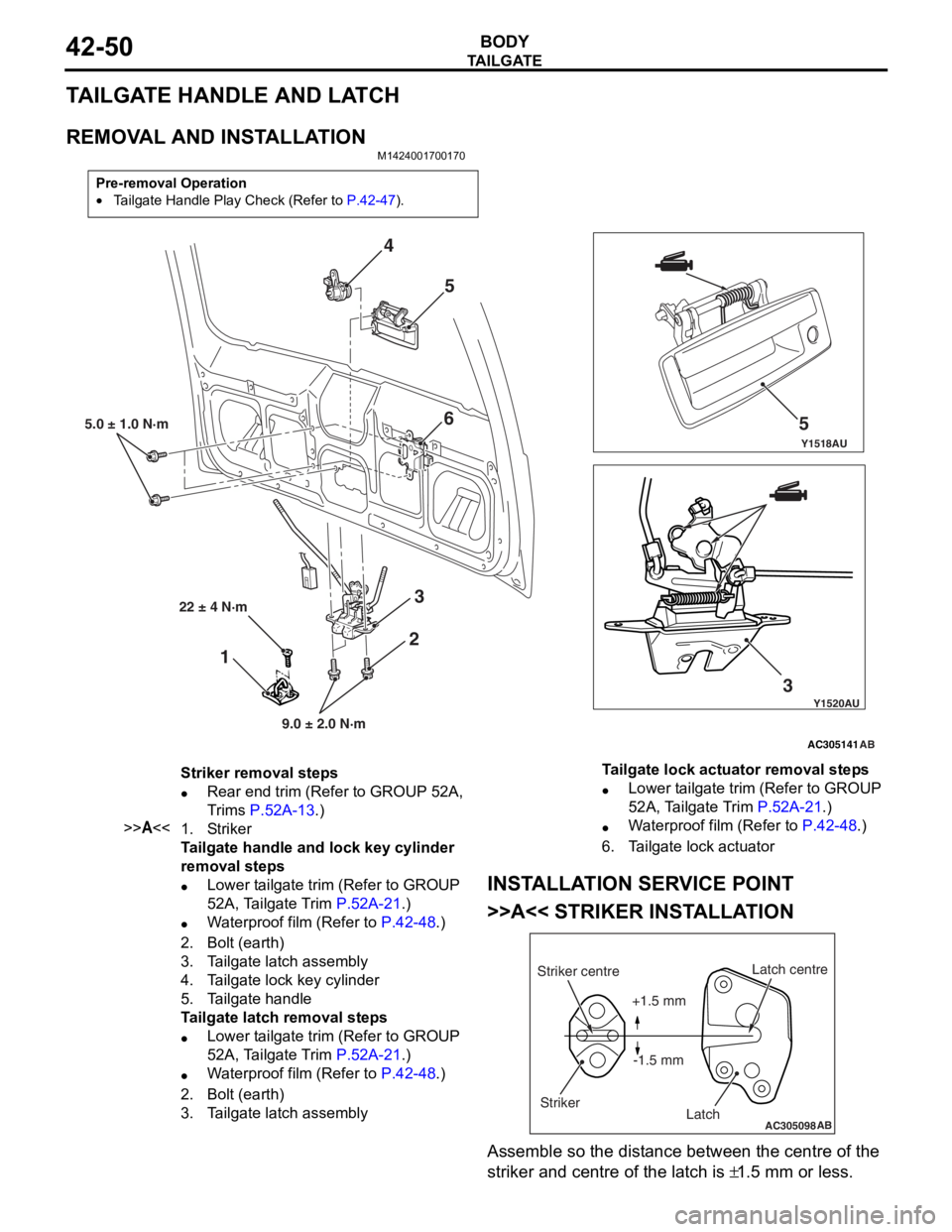
Striker removal steps
•Rear end trim (Refer to GROUP 52A,
Trims
P.52A-13.)
>>A<<1.Strik er
Tailgate handle and lock key cylinder
removal steps
•Lower tailgate trim (Refer to GROUP
52A, Tailgate Trim
P.52A-21.)
•Waterproof film (Refer to P.42-48.)
2.Bolt (earth)
3.Tailgate latch assembly
4.Tailgate lock key cylinder
5.Tailgate handle
Tailgate latch removal steps
•Lower tailgate trim (Refer to GROUP
52A, Tailgate Trim
P.52A-21.)
•Waterproof film (Refer to P.42-48.)
2.Bolt (earth)
3.Tailgate latch assembly
Tailgate lock actuator removal steps
•Lower tailgate trim (Refer to GROUP
52A, Tailgate Trim
P.52A-21.)
•Waterproof film (Refer to P.42-48.)
6.Tailgate lock actuator
INSTALLA T ION SER VICE POINT
>>A<< STRIKER INST ALLA TION
AC305098AB
Striker centre
Striker Latch centre
Latch
+1.5 mm
-1.5 mm
Assemble so the dist ance between the centre of the
striker an
d ce ntre of t he la tch is
±1.5 mm or less.
Page 323 of 800
KEYLESS ENTRY SYSTEM
BODY42-51
INSPECTION
M1424001200142
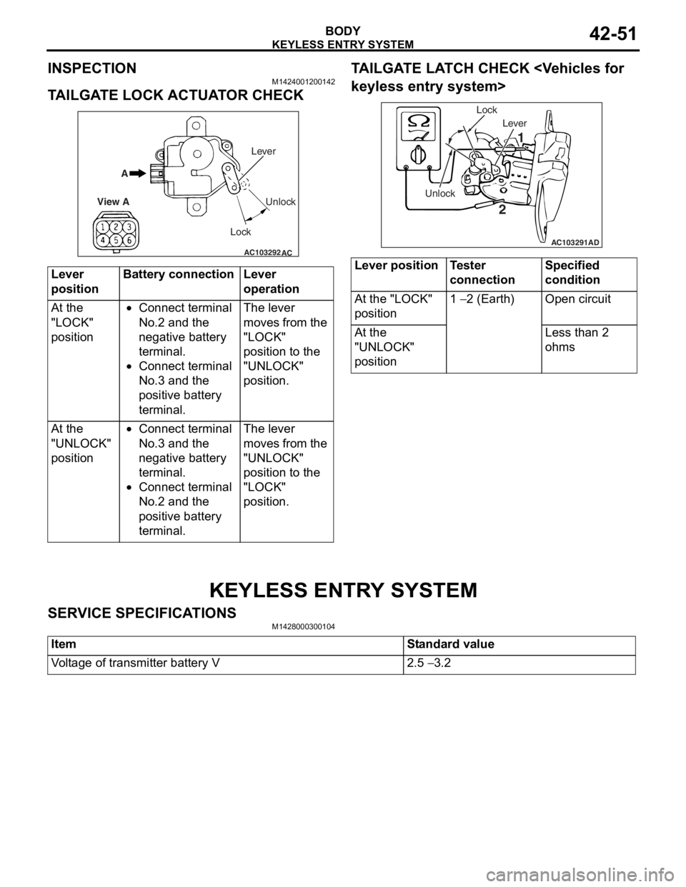
TAILGATE LOCK ACTUATOR CHECK
AC103292
A
View A Unlock
Lock Lever
AC
Lever
positionBatte
ry connec tionLever
o
peration
At the
"LOCK"
position•Conn ect t e rminal
No.2
and th e
ne
gative ba ttery
te
rmin al.
•Connect t e rminal
No.3
and th e
po
sit i ve battery
te
rmin al.
The le ver
moves f
r om the
"LOCK"
p
o sition t o the
"UNLOCK
"
p
o sition.
At the
"UNLOCK"
position•Conn ect t e rminal
No.3
and th e
ne
gative ba ttery
te
rmin al.
•Connect t e rminal
No.2
and th e
po
sit i ve battery
te
rmin al.
The le ver
moves f
r om the
"UNLOCK
"
p
o sition t o the
"LOCK"
p
o sition.
TA ILGA TE LA TCH CHECK
ess entry system>
AC103291
Lever
Unlock Lock
1
2
AD
Lever positionTester
connectionSpecified
condition
At the "LOCK"
position1 − 2 (Earth)Open circuit
At the
"UNLOCK"
positionLess than 2
ohms
KEYLESS ENTR Y SYSTEM
SERV ICE SPECIFICA T IONS
M14280003 0010 4
ItemStandard value
Voltage of transmitter battery V2.5 − 3.2
Page 324 of 800
KEYLESS ENTRY SYSTEM
BODY42-52
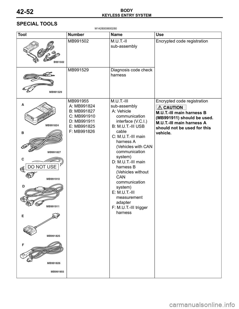
SPECIAL TOOLS
M1428000600280
ToolNumberNameUse
B991502
MB991502M.U.T . -II
su
b-assemblyEn cryp ted code re gistration
MB991529
MB991529Diagnosis code check
harn
e ss
MB991910
MB991826
MB991955
MB991911
MB991824
MB991827
MB991825
A
B C
D
E F
DO NOT USE
MB991 955
A: MB9918 24
B: MB991827
C: MB99191 0
D: MB991911
E: MB991825
F: MB991 826
M.U.T . -III
su
b-assembly
A: V ehicle
commun ica t ion
inte rface (V .C.I.)
B: M.U.T. -III USB
cab l e
C: M.U.T . -III main
harne ss A
(V ehicles wi th CAN
commun ica t ion
sy stem )
D: M.U.T. -III main
harne ss B
(V ehicles witho u t
CA N
commun ica t ion
sy stem )
E: M.U.T. -III
mea s urement
adapt er
F: M.U.T . -III t r igger
harne ss
Encryp ted code re gistration
M.U.T.-III main harness B
(MB991911) should be used.
M.U.T.-III main harness A
should not be used for this
vehicle.
CAUTION