check MITSUBISHI LANCER IX 2006 Service Manual
[x] Cancel search | Manufacturer: MITSUBISHI, Model Year: 2006, Model line: LANCER IX, Model: MITSUBISHI LANCER IX 2006Pages: 800, PDF Size: 45.03 MB
Page 325 of 800
KEYLESS ENTRY SYSTEM
BODY42-53
TROUBLESHOOTING
M1428000700287
The keyless entry system is controlled by the Smart
Wiring System (SWS). For troubleshooting, refer to
GROUP 54B, Troubleshooting
P.54B-15 or GROUP
54C, Troubleshooting P.54C-4.
ON-VEHICLE SERVICE
KEYLESS ENTR Y SYSTEM CHECKM1428001400096
Check the system as described below. If the system
does not work, carry out troubleshooting. Refer to
GROUP 54B, Troubleshooting
P.54B-15, refer to
GROUP 54C, Troubleshooting P.54C-4.
•Operate the transmitter to check that the doors
and tailgate can be locked and unlocked.
•Operate the transmitter to check that the answer-
back function works in response to door and tail-
gate
NOTE: The adjustment function allows you to
change the answerback setting as follows. Prior
to that check, confirm which setting is activated.
.
•The hazard warning lamps flash twice when
locked and once when unlocked. The room
lamp flashes twice when locked and illumi
-
nates for 15 seconds when unlocked.
•The hazard warning lamps do not flash when
locked and flash once when unlocked. The
room lamp flashes twice when locked and illu
-
minates for 15 seconds when unlocked.
•The hazard warning lamps flash twice when
locked and do not flash when unlocked. The
room lamp flashes twice when locked and illu
-
minates for 15 seconds when unlocked.
•The hazard warning lamps do not flash when
both locked and unlocked. The room lamp
flashes twice when locked and illuminates for
15 seconds when unlocked.
KEYLESS ENTRY SYS TEM TIMER LOCK
FUNCTION INSPECTION
M1428004000138
Push the transmitter unlock button and check to see
that the doors and tailgate
seconds. If it doesn't, then execute troubleshooting
remedies. Refer to GROUP 54B, Troubleshooting
P.54B-15, refer to GROUP 54C, Troubleshooting
P.54C-4.
ENABLING/DISABLING THE
ANSWERBACK FUNCTION
M1428003200214
If the keyless entry system locks or unlocks the
doors, the room lamp flashes or illuminates, the haz
-
ard warning lamp flashes (hazard answerback func-
tion). The hazard answerback function can be
enabled or disabled according to the following proce
-
dure:
ENABLING/DISABLING THE HAZARD
ANSWERBACK FUNCTION
The hazard answerback function can be enabled or
disabled by one of the two following procedures.
1. Enter the hazard answerback customize mode by performing one of the following steps. If the
ETACS-ECU enters the customize mode, its
buzzer will sound once.
(1) Turn the ignition switch to “LOCK”(OFF) position.
(2) Turn off the hazard warning lamp switch.
CAUTION
Before connecting or disconnecting the earth,
turn the ignition switch to the "LOCK" (OFF)
position.
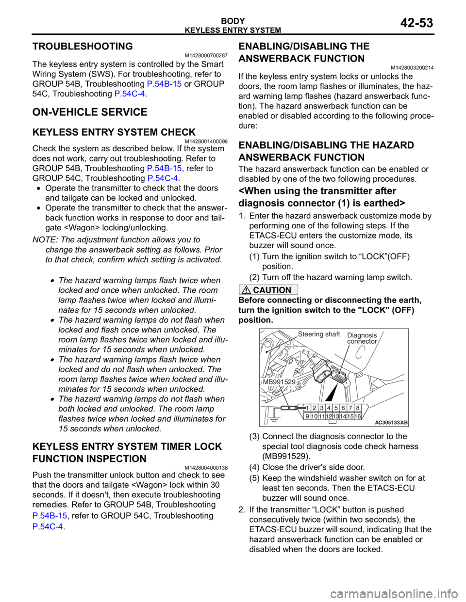
AC305133AB
Diagnosis
connector
MB991529Steering shaft
(3) Connect the diagnosis connector to the special tool diagnosis code check harness
(MB991529).
(4) Close the driver's side door.
(5) Keep the windshield washer switch on for at least ten seconds. Then the ETACS-ECU
buzzer will sound once.
2. If the transmitter “LOCK” button is pushed consecutively twice (wit hin two seconds), the
ETACS-ECU buzzer will sound, indicating that the
hazard answerback function can be enabled or
disabled when the doors are locked.
Page 328 of 800
KEYLESS ENTRY SYSTEM
BODY42-56
WHEN THE SPECIAL TOOL DIAGNOSIS
CODE CHECK HARNESS (MB991529) IS
USED
1. Check that the doors lock normally when the key is used.
2. Insert the ignition key.
CAUTION
Before connecting or disconnecting the earth,
turn the ignition switch to the "LOCK" (OFF)
position.
AC305133AB
Diagnosis
connector
MB991529Steering shaft
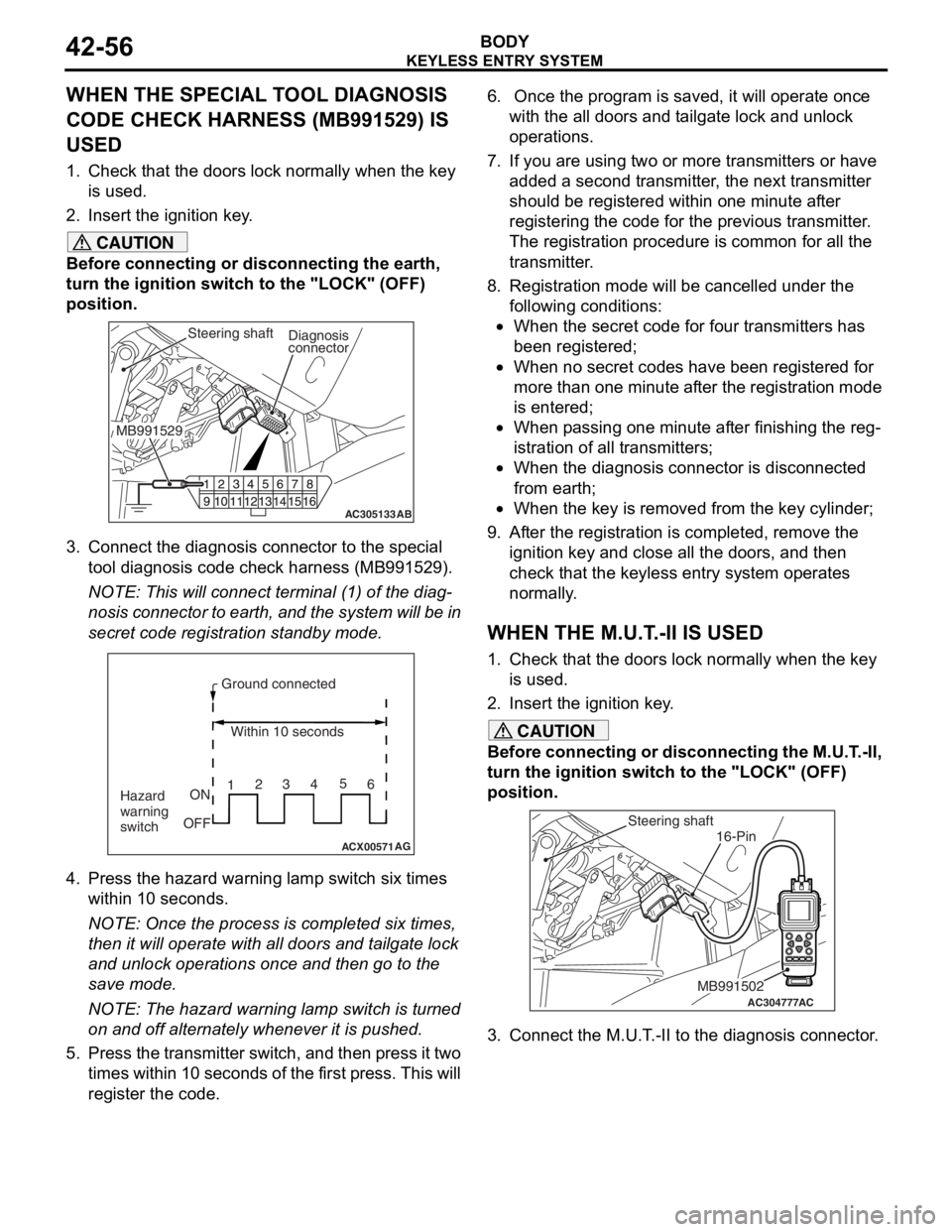
3. Connect the diagnosis connector to the special tool diagnosis code check harness (MB991529).
NOTE: This will connect terminal (1) of the diag-
nosis connector to earth, and the system will be in
secret code registration standby mode.
ACX00571
Ground connected
Within 10 seconds
Hazard
warning
switch ON
OFF 1
23
45
6
AG
4. Press the hazard warning lamp switch six times
within 10 seconds.
NOTE: Once the process is completed six times,
then it will operate with al l doors and tailgate lock
and unlock operations once and then go to the
save mode.
NOTE: The hazard warning lamp switch is turned
on and off alternately whenever it is pushed.
5. Press the transmitter switch, and then press it two times within 10 seconds of the first press. This will
register the code.
6. Once the program is saved, it will operate once
with the all doors and tailgate lock and unlock
operations.
7. If you are using two or more transmitters or have
added a second transmitter, the next transmitter
should be registered within one minute after
registering the code for the previous transmitter.
The registration procedure is common for all the
transmitter.
8. Registration mode will be cancelled under the following conditions:
•When the secret code for four transmitters has
been registered;
•When no secret codes have been registered for
more than one minute after the registration mode
is entered;
•When passing one minute after finishing the reg-
istration of all transmitters;
•When the diagnosis connector is disconnected
from earth;
•When the key is removed from the key cylinder;
9. After the registration is completed, remove the ignition key and close all the doors, and then
check that the keyless entry system operates
normally.
WHEN THE M.U.T.-II IS USED
1. Check that the doors lock normally when the key
is used.
2. Insert the ignition key.
CAUTION
Before connecting or disconnecting the M.U.T.-II,
turn the ignition switch to the "LOCK" (OFF)
position.
AC304777
Steering shaft
ACMB991502
16-Pin
3. Connect the M.U.T.-II to the diagnosis connector.
Page 329 of 800
ACX00571
M.U.T.-II connectedWithin 10 seconds
Hazard
warning
switch ON
OFF 1
23
45
6
AB
KEYLE SS ENTR Y SYSTEM
BOD Y42-57
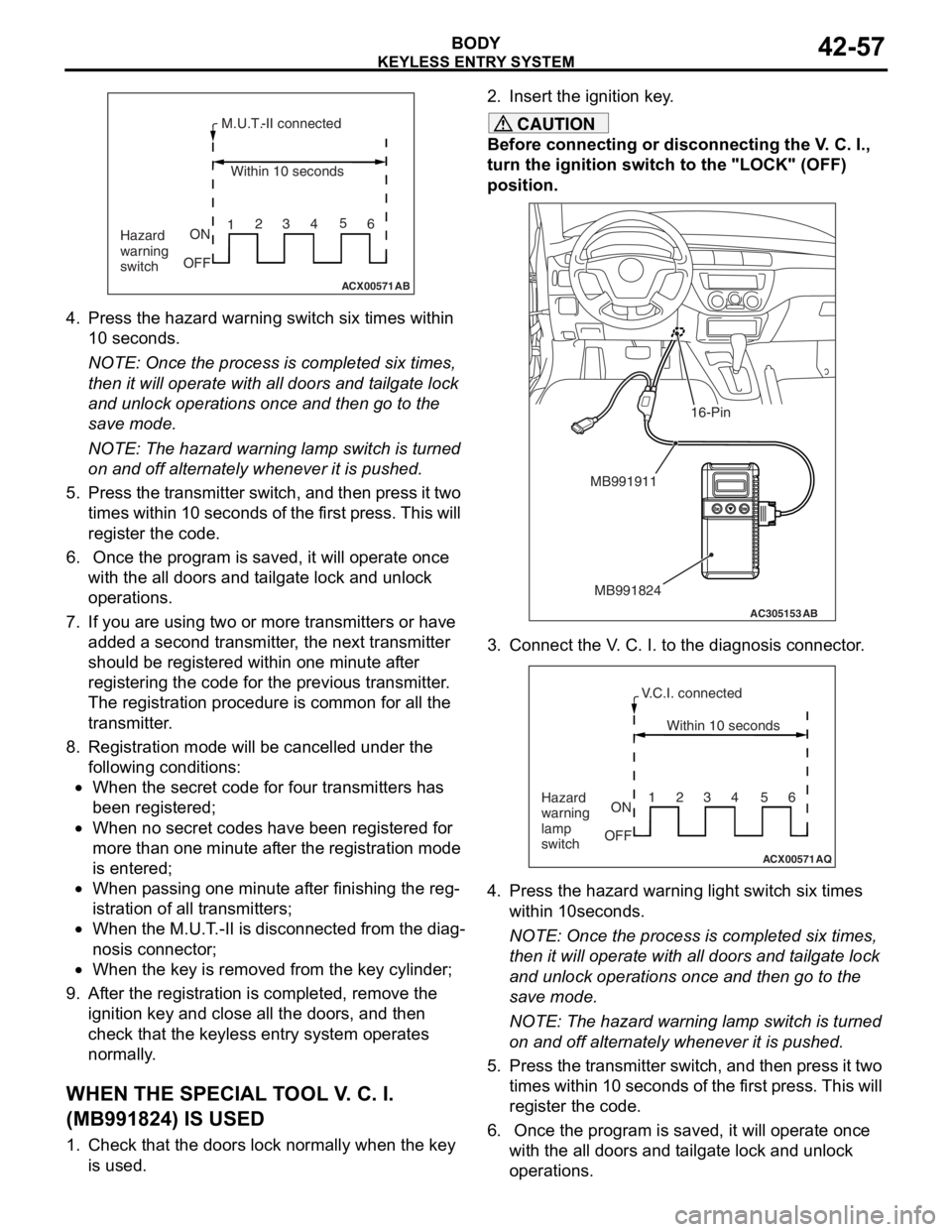
4.Press th e hazard warning switch six times within
10 seconds.
NOTE: Once th e process is comple ted six t i me s,
th
en it
will operate with al l do ors an d t a ilgate lock
an
d unlock opera t ions once and then go to th e
save
mode .
NOTE: The h a zard warnin g lamp switch is turned
on
and o ff alt e rnately when ever it is pushed.
5.Pre s s th e tr ansmitter switch, a nd then pre s s it two
t i mes within 10 second s of th e f i rst pre s s. This will
reg i st er the code.
6. Once the p r ogram is saved, it will opera t e once
wit h the a ll d oors a nd t a ilgate lock and unlo ck
op erations.
7.If you a r e using t w o or mo re transmitters or have
ad ded a second tra n smitter , the n e xt tra n smitter
should be re gistered within o ne minute af ter
reg i st ering the code fo r the pre v io us tra n smitter .
Th e registration pr oced ure is co mmo n for a ll th e
tra n smitter .
8.Registra tion mode will be ca ncelled under the
fo llowing condit i ons:
•When the secr et co de for fo ur transmitters has
bee
n registere d ;
•When no secre t cod e s h a ve b een re gist ered fo r
more tha
n one minute af ter the registration mode
is ente
r ed;
•When p a ssing o ne minute af ter fin i sh ing t he reg-
istration of all t r ansmitte rs;
•When the M.U.T . -II is d i sconne cted from th e dia g-
nosis connecto r;
•When the key is re moved fro m the key cylin der;
9.Af ter the registration is completed, remove the
ignition key a nd close all the d oors, and th en
check tha t the keyless entry syste m op erates
no rmally .
WH EN THE SPECIAL T O OL V . C. I.
(
M B991824) I S USED
1.Check t hat the doors lock n o rmally wh en the key
is used.
2. In sert t he ig nition ke y .
CAUTION
Before connecting or disconnecting the V. C. I.,
turn the ignition switch to the "LOCK" (OFF)
position.
AC305153AB
MB991911
MB991824
16-Pin
3. Connect the V. C. I. to the diagnosis connector.
ACX00571
Within 10 seconds
Hazard
warning
lamp
switch ON
OFF 1234 56
AQ
V.C.I. connected
4. Press the hazard warning
light switch six times
within 10seconds.
NOTE: Once the process is completed six times,
then it will operate with all doors and tailgate lock
and unlock operations once and then go to the
save mode.
NOTE: The hazard warning lamp switch is turned
on and off alternately whenever it is pushed.
5. Press the transmitter switch, and then press it two times within 10 seconds of the first press. This will
register the code.
6. Once the program is saved, it will operate once with the all doors and tailgate lock and unlock
operations.
Page 330 of 800
KEYLESS ENTRY SYSTEM
BODY42-58
7. If you are using two or more transmitters or have added a second transmitter, the next transmitter
should be registered within one minute after
registering the code for the previous transmitter.
The registration procedure is common for all the
transmitter.
8. Registration mode will be cancelled under the following conditions:
•When the secret code for four transmitters has
been registered;
•When no secret codes have been registered for
more than one minute after the registration mode
is entered;
•When passing one minute after finishing the reg-
istration of all transmitters;
•When the V.C.I. is disconnected from the diagno-
sis connector;
•When the key is removed from the key cylinder;
9. After the registration is completed, remove the ignition key and close all the doors, and then
check that the keyless entry system operates
normally.
TRANSMITTER
DISASSEMBLY AND REASSEMBLY
M1428002800172
Post-reassembly operation
•Transmitter operation check
AC310838AC303199
AC3041181
2
AF
5
3
4
6
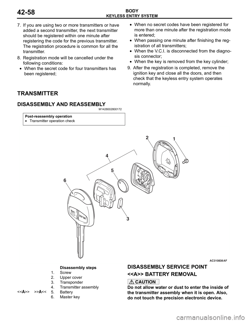
Disassembly steps
1.Screw
2.Upper cover
3.Transponder
4.Transmitter assembly
<>>>A<<5.Battery
6.Master key
DISASSEMBL Y SER V ICE POINT
<> BATTER Y REMOV A L
CAUTION
Do not allow water or dust to enter the inside of
the transmitter assembly when it is open. Also,
do not touch the precision electronic device.
Page 331 of 800

KEYLESS ENTRY SYSTEM
BODY42-59
REASSEMBLY SERVICE POINT
>>A<< BATTERY INSTALLATION
CAUTION
Do not allow water or dust to enter the inside of
the transmitter assembly when it is open. Also,
do not touch the precision electronic device.
AC304118AD
+
–
Master key side Upper cover side
Battery
Transmitter assembly
Install a new battery to the transmitter assembly with
its (+) side facing towards the upper cover side.
Battery required for replacement: Coin type
battery CR1616
INSPECTION
M1428003800067
TRANSMITTER BATTERY CHECK
AC004486
Measure the voltage of the battery. If the voltage of
the battery is not within the standard value, replace
the battery.
Standard value: 2.5 − 3.2 V
Page 343 of 800
MOULDINGS
EXTERIOR51-11
INSTALLATION SERVICE POINTS
>>A<< DRIP MOULDING CLIP C/DRIP
MOULDING CLIP B/DRIP MOULDING
CLIP A INSTALLATION
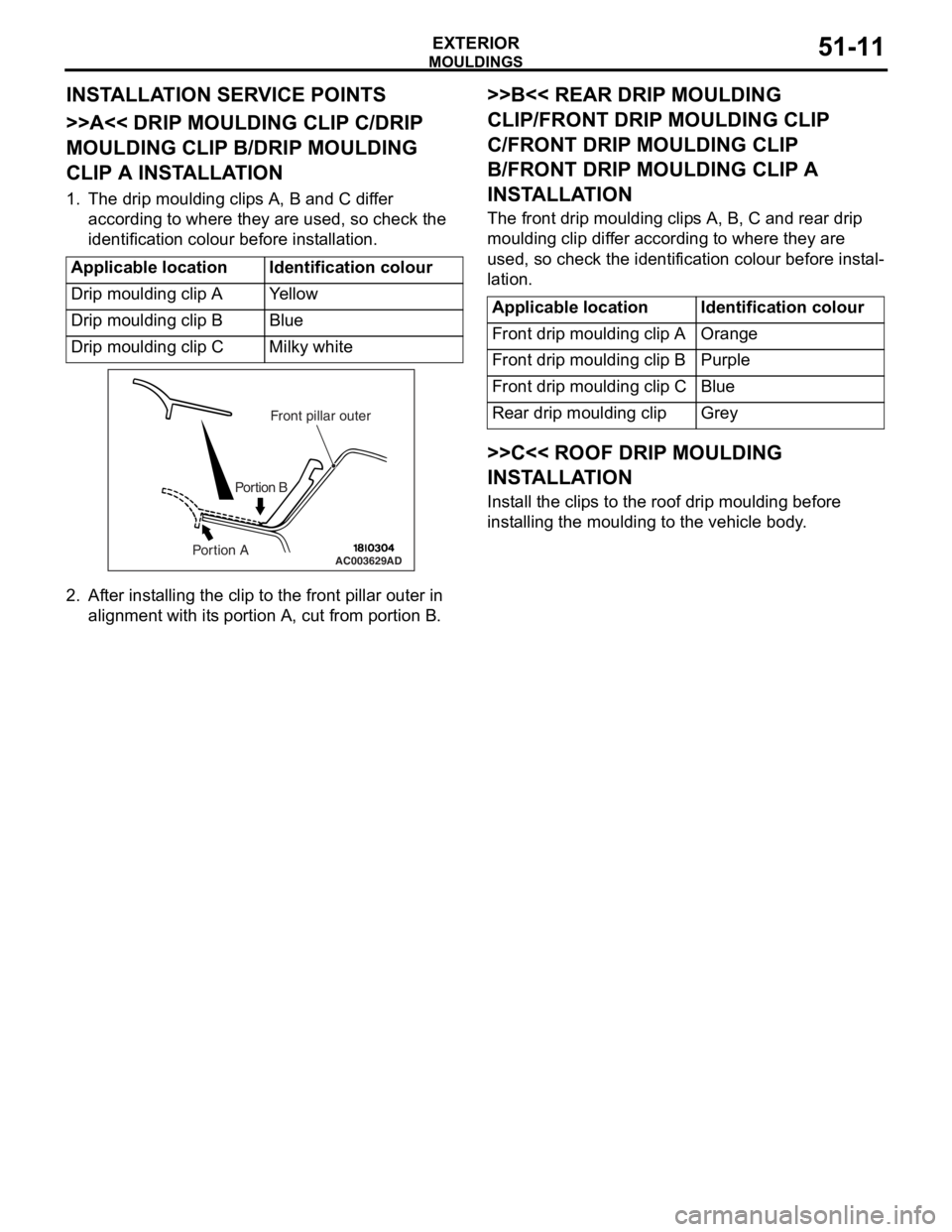
1. The drip moulding clips A, B and C differ according to where they are used, so check the
identification colour before installation.
Applicable locationIdentification colour
Drip moulding clip AYe l l o w
Drip moulding clip BBlue
Drip moulding clip CMilky white
AC003629
Front pillar outer
Portion B
Portion AAD
2. Af ter inst alling the clip to the f r ont pilla r outer in
align m ent with it s portio n A, cu t from portion B.
>>B<< REAR DRIP MOULDING
CLIP/FRONT DRIP MOULDING CLIP
C/FRONT DRIP MOULDING CLIP
B/FRONT DRIP MOULDING CLIP A
INST
ALLA TION
The front drip mou l din g clip s A, B, C an d rear d r ip
moulding
clip dif f er accordin g to where they are
used
, so check th e ide n tification colou r before inst al
-
lation.
Applicable locationIdentification colour
Front drip moulding clip AOrange
Front drip moulding clip BPurple
Front drip moulding clip CBlue
Rear drip moulding clipGrey
>>C<< ROOF DRIP MOULDING
INSTALLA TION
Install the clip s to th e roof d r ip mould i ng before
inst
allin g the moulding to the vehicle body .
Page 362 of 800

MB991529
WINDSHIELD WI PER AND W A SHER
EXTERIOR51-30
TROUBLESHOOTING
M151 1 0007 0032 3
The windshield wiper and washe r are controlled b y
the Sma
r t Wiring System (SWS). For tro ubleshoo t
-
ing, refer to GROUP 54B, T r ouble s ho oting P.54B-15
or GROUP 54 C, T r oublesho oting P.54C-4.
NOTE: Eve n when th e ET ACS-ECU h a s fa ile d, the
windsh
i eld wiper can work at low spe ed as fail-safe
mode
. (Normally , th e windshie l d wip e r opera t es
wh
en t
h e ign i tio n swit ch i s at th e "ACC" pos itio n. Bu t,
if it
enters the fa il-safe mode, the wip e r can opera t e
only when th e ign i tio n switch is at t he "ON" p o sition. )
ON-VEHICLE SERV ICE
M151 1 0008 0046 1
WI NDSHIELD INTERMITTENT WIPER
INSPECTION
1. If the win d shield intermitte nt wiper interval
a d justing knob is operate d , the wiper interval
should ch ange.
2.Holding the win d shield intermitte nt wiper interval
a d justing kno b , input t he simu lated ve hicle speed
with M.U.T . -I I / II I a nd check th at the wipe r inte rval
chang es as the v ehicle spe ed changes.
3.If not, carry o u t the troublesho oting (Refer to
GROUP 54B, T r ou bleshoot ing
P.54B-15 or
GROUP 54C, T r ou bleshooting P.54C-4).
MB991529Diagnosis code check
harn
e ssInput sign al check by using a
voltm
e ter
MB991223
a
d c
b
DO NOT USE
BA
MB991 223
a. MB99121 9
b. MB99122 0
c.MB99122 1
d. MB99122 2
Harness set
a.Check harne ss
b.LED harness
c.LED harness
adapt er
d.Probe
Con t inuity check an d vo lt age
measurement at
harness wire or
conn
ector
a.Fo r che cking connector pin
cont act pressure
b.Fo r che cking po we r sup p ly
circuit
c. Fo r che cking po we r sup p ly
circuit
d.Fo r con necting a locally
sourced tester
MB992006
MB992 006Extra fine probeCont inuity check an d vo lt age
measurement at
harness wire or
conn
ector
Tool Nu mber Name Use
Page 364 of 800

Wiper blade assembly removal steps
>>B<<1.Wiper blade assembly
>>A<<2.Wiper blade
Windshield wiper motor and link
assembly removal steps
3.Cover
4.Wiper arm
5.Hood weather strip
6.Front deck garnish (passenger's side)
7.Front deck garnish (driver's side)
<>8.Windshield wiper motor assembly
9.Link assembly
Washer hose removal steps
•Front splash shield (Refer to GROUP
42, Fender
P.42-6)
10.Rear washer hose
11 .Front washer hose
Windshield washer nozzle removal
steps
•Connection of front washer hose
11 .Washer nozzle
Washer tank and washer motor
removal steps
•Side undercover (RH)
•Front splash shield (Refer to GROUP
42, Fender
P.42-6)
•Connection of front washer hose and
rear washer hose
12.Washer tank assembly
13.Front washer motor
14.Rear washer motor
WINDSHIELD W I PER AND W A SHER
EXTERIOR51-32
NOTE: For re moval a nd in st allation of the wiper an d
washer switch, refer to GROUP 54A, Colu mn switch
P.5 4 A - 89.
REMOV A L SER V ICE POINT
<> WI NDSHIELD W I PER MOT O R
ASSEMBL
Y REMOV A L
AC304411AB
Windshield wiper
motor assembly
Link assembly
connection
Flat-tipped screwdriver
1.
Remove the win d shield wiper motor asse mbly
mounting bo lt.
CAUTION
Be careful not to damage the windshield glass
when the windshield wiper motor assembly is
removed.
2. Use the flat-tipped screwdriver to disengage the link between the windshield wiper motor assembly
and the link assembly to remove the windshield
wiper motor assembly.
INSTALLATION SERVICE POINTS
>>A<< WIPER BLADE INSTALLATION
AC101090 AD
Wiper blade Backing
Backing A
A
Section A – A
Wiper
blade Backing
CAUTION
The driver's side wiper blade is not warped.
When installing the passenger's wiper blade, check
that the backing inside the wiper blade is warped
toward the wiper arm.
>>B<< WIPER BLADE ASSEMBLY
INSTALLATION
AC000427
A
A
Front deck garnish terminalAD
Install the wiper blade at the specified position
(standard value).
Standard value (A): 34 ± 5 mm
Page 365 of 800
WINDSHIELD WIPER AND WASHER
EXTERIOR51-33
INSPECTION
M1511007700313
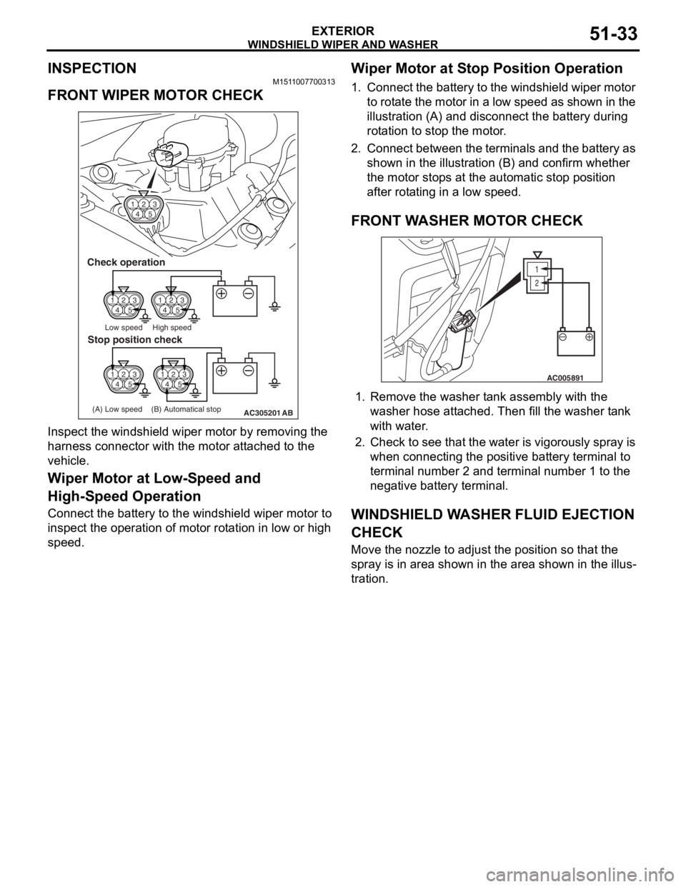
FRONT WIPER MOTOR CHECK
14 23
5
14 23
514 23
5
14 23
5
AC305201
14 23
5
Check operation
Low speed High speed
(A) Low speed (B) Automatical stop
Stop position check
AB
Inspe c t th e windshie l d wipe r mot o r by removing the
harness connector wit
h the motor a t t a ched to the
vehicle
.
Wiper Motor at Low-S peed and
High-S
peed Operation
Connect the ba ttery to the windsh i eld wiper motor to
insp
ect the ope ration of motor rot a tion in low or high
spee
d.
Wiper Motor at S t op Position Operation
1.Conn ect t he batt e ry to the wind shield wip e r mot o r
to rot a te th e motor in a low sp eed a s shown in the
illu stration (A) an d disco nnect the ba ttery durin g
ro t a tion to stop the motor .
2.Co nn ect b e t w ee n t h e te rmin als an d the b a tt ery as
shown in the illu strat i on (B) a nd co nfirm whether
th e mo tor sto p s at th e auto m atic stop po sition
a f ter rot a ting in a low sp eed.
FRONT WA SHER MOT O R CHECK
1
2
AC005891
1.Remove t he wash er t ank assembly wit h the
washer hose att a ched. T hen fill t he wash er t ank
with wa ter .
2.Check to see that th e wa ter is vigo rously sp ray is
when conn ecting the positive batt e ry te rmin al to
termina l number 2 and te rmin al nu mber 1 to th e
neg ative batt e ry te rmin al.
WI NDSHIELD W A SHER FLUID EJECTION
CHECK
Move the nozzle to adjust th e position so that th e
spray is in a
r ea shown in the are a sh own in t he illus
-
tration.
Page 366 of 800

AC304420
305
70
25
55 140
100
120 115
305 300
600
3002525
25
25
25
25
25
55
6560
50
60
50
AB
Windshield washer
nozzle perpendicular
Windshield washer
nozzle perpendicular
Windshield washer nozzle
Ceramic line terminal
UNITS: mm
WINDSHIELD WI PER AND W A SHER
EXTERIOR51-34
WI NDSHIELD W I PER AND WINDSHIELD
W
A SHER SWIT CH CHECK
1
6
8
11 10 9 7
5 4
3
2
AC000417
Che
c k cont inuity be tween th e switch ter m in als.
Switch positionTester
connectionSpecified
condition
OFF6 − 11 , 6 − 10,
6 − 9, 6 − 8, 6 −
7
Open circuit
Windshield mist
wiper switch6 − 11Less than 2
ohms
Windshield
intermittent wiper
switch6 − 10
Windshield
low-speed wiper
switch6 − 9
Windshield
high-speed wiper
switch6 − 8
Windshield
washer switch6 − 7