check MITSUBISHI LANCER IX 2006 Service Manual
[x] Cancel search | Manufacturer: MITSUBISHI, Model Year: 2006, Model line: LANCER IX, Model: MITSUBISHI LANCER IX 2006Pages: 800, PDF Size: 45.03 MB
Page 252 of 800

STEERING COLUMN SHAFT ASSEMBLY
POWER STEERING37-22
DISASSEMBLY AND REASSEMBLY
M1372015000068
AC210967AD
3
2
14
Disassembly steps
<>>>A<<1.Special bolt
>>A<<2.Steering lock bracket
>>A<<3.Steering lock cylinder assembly
4.Steering column shaft assembly
DISASSEMBL
Y SER V ICE POINT
<> SPECIAL BOLT REMOV A L
ACX01138
AB
Steering lock
bracket
Reverse screw tap
Special bolt
Steering lock
cylinder
1. Drill in the special bo lt a ho le de ep enou gh for th e
t ap t o st and.
2.Remove the special b o lt with a lef t -h and t ap.
REASSEMBL Y SER V ICE POINT
>>A<< STEERING LOCK CYLINDER
ASSEMBL
Y /STEERING LOCK
BRACKET/SPECIAL BOL
T INST ALLA
-
TION
CAUTION
The steering lock bracket and bolts must be
replaced with new ones when the steering lock is
installed.
1. When installing the steering lock cylinder assembly and steering lock bracket to the column
tube, temporarily install the steering lock in
alignment with the column boss.
ACX01139 AB
2. After checking that the lock works properly,
tighten the special bolts until the head twists off.
Page 253 of 800
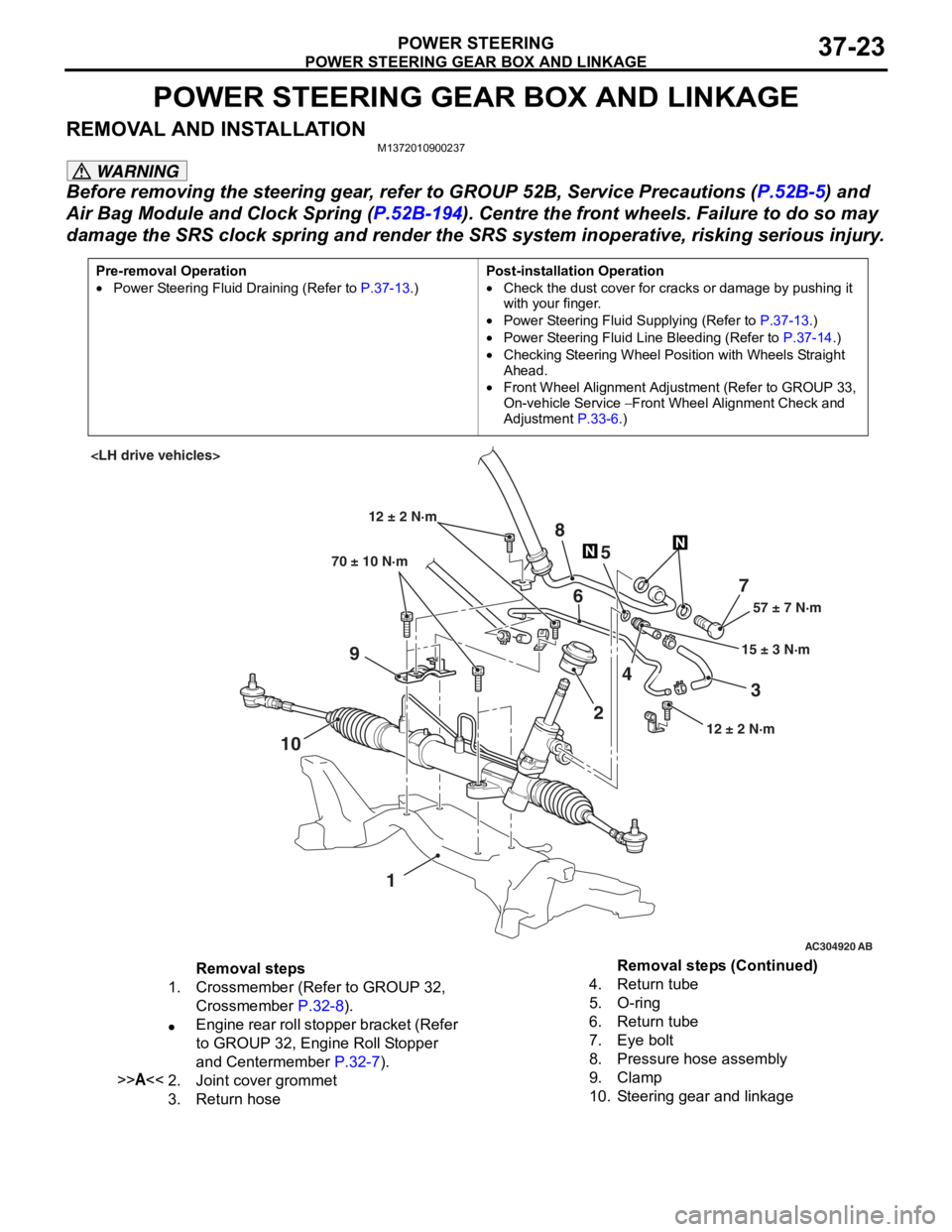
POWER STEERING GEAR BOX AND LINKAGE
POWER STEERING37-23
POWER STEERING GEAR BOX AND LINKAGE
REMOVAL AND INSTALLATIONM1372010900237
WARNING
Before removing the steering gear, refer to GROUP 52B, Service Precautions (P.52B-5) and
Air Bag Module and Clock Spring (P.52B-194). Centre the front wheels. Failure to do so may
damage the SRS clock spring and render the SRS system inoperative, risking serious injury.
Pre-removal Operation
•Power Steering Fluid Draining (Refer to P.37-13.)
Post-installation Operation
•Check the dust cover for cracks or damage by pushing it
with your finger.
•Power Steering Fluid Supplying (Refer to P.37-13.)
•Power Steering Fluid Line Bleeding (Refer to P.37-14.)
•Checking Steering Wheel Position with Wheels Straight
Ahead.
•Front Wheel Alignment Adjustment (Refer to GROUP 33,
On-vehicle Service
− Front Wheel Alignment Check and
Adjustment
P.33-6.)
AC304920 AB
57 ± 7 N·m
15 ± 3 N·m
70 ± 10 N·m
7
3
8
5
6
9
10 24
1
12 ± 2 N·m
12 ± 2 N·m
Removal steps
1.Crossmember (Refer to GROUP 32,
Crossmember
P.32-8).
•Engine rear roll stopper bracket (Refer
to GROUP 32, Engine Roll Stopper
and Centermember
P.32-7).
>>A<<2.Joint cover grommet
3.Return hose
4.Return tube
5.O-ring
6.Return tube
7.Eye bolt
8.Pressure hose assembly
9.Clamp
10.Steering gear and linkage
Removal steps (Continued)
Page 254 of 800
AC304921AC
57 ± 7 N·m 15 ± 3 N·m
70 ± 10 N·m
3
5 2
4
1
67
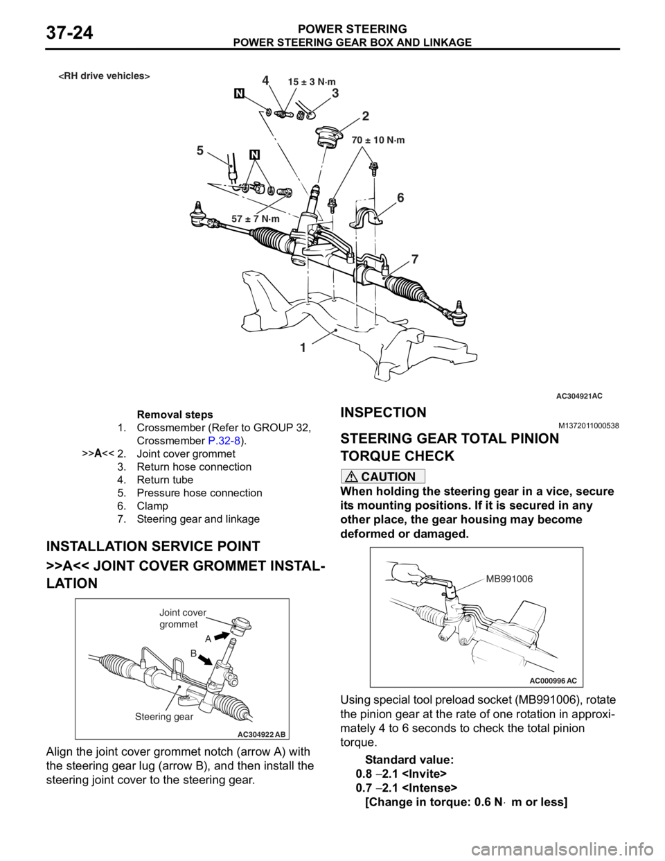
Removal steps
1.Crossmember (Refer to GROUP 32,
Crossmember
P.32-8).
>>A<<2.Joint cover grommet
3.Return hose connection
4.Return tube
5.Pressure hose connection
6.Clamp
7.Steering gear and linkage
PO WE R STEER ING GEAR BOX AND LINK AGE
POWER ST E E RING37-24
INSTALLA T ION SER VICE POINT
>>A<< JOINT COVER GROMMET INST AL-
LATION
AC304922AB
A
B
Joint cover
grommet
Steering gear
Align the jo int cove r grommet n o tch (arrow A) with
the steerin
g gear lug (a rrow B), and t hen inst all the
steering joint
cover to th e ste e ring gear .
INSPECTIONM137201 10 0053 8
STEERING GEAR T O T A L PINION
T
O RQUE CHECK
CAUTION
When holding the steering gear in a vice, secure
its mounting positions. If it is secured in any
other place, the gear housing may become
deformed or damaged.
AC000996 AC
MB991006
Using special tool preload socket (MB991006), rotate
the pinion gear at the rate of one rotation in approxi
-
mately 4 to 6 seconds to check the total pinion
torque.
Standard value:
0.8 − 2.1
0.7 − 2.1
[Change in torque: 0.6 N⋅m or less]
Page 255 of 800
POWER STEERING GEAR BOX AND LINKAGE
POWER STEERING37-25
NOTE: When measuring, remove the bellows from
the rack housing. Measure the pinion torque through
the whole stroke of the rack.
If the measured value is not within the standard
range, first adjust the rack support cover, and then
check the total pinion torque again.
If the total pinion torque cannot be adjusted to within
the standard range by adjusting the rack support
cover, check the rack support cover, rack support
spring, rack support and replace any parts if neces
-
sary.
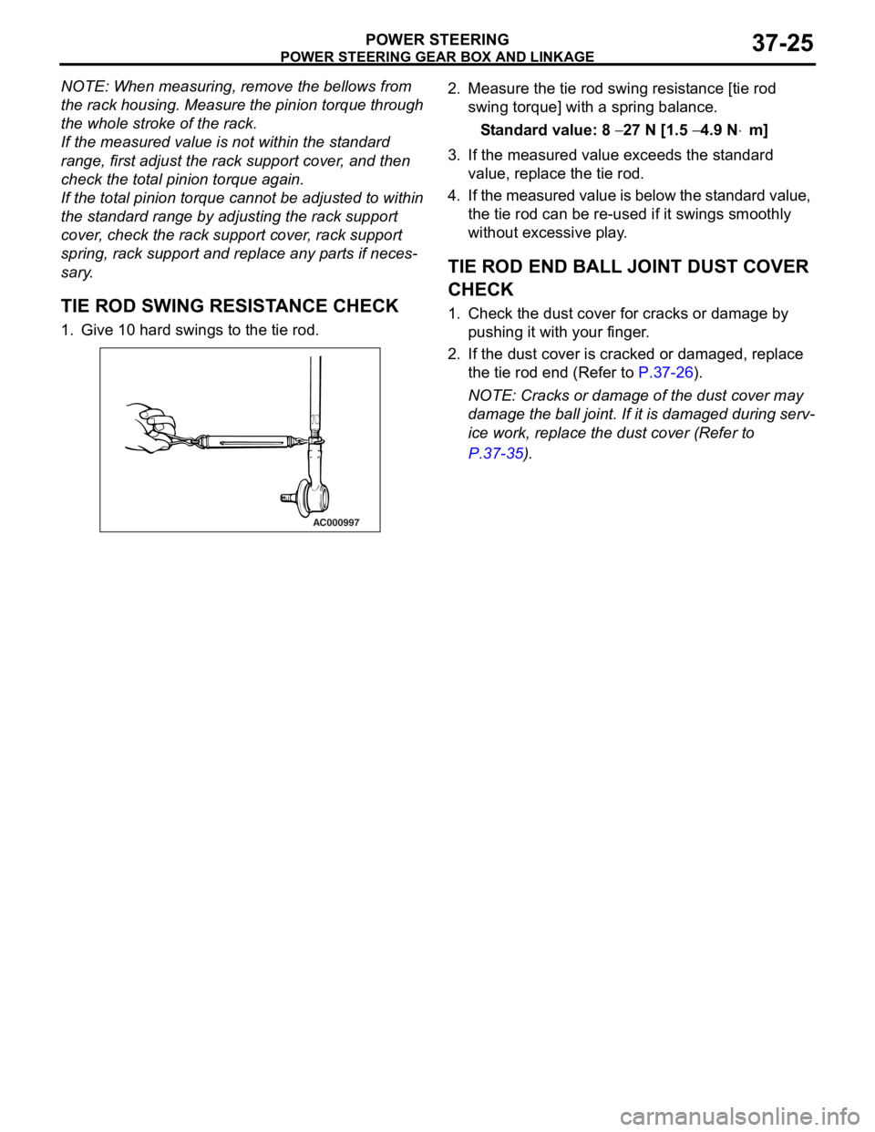
TIE ROD SWING RESISTANCE CHECK
1. Give 10 hard swings to the tie rod.
AC000997
2. Measure the tie ro d swin g resist ance [tie rod
swing to rque] with a spring bala n ce.
St andard va lue: 8 − 27 N [1.5 − 4.9 N⋅m]
3.If the measu r ed value exceeds the st a ndard
value , replace the tie rod.
4. If the measured value is below the st a ndard valu e,
th e tie rod can be re-use d if it swings smo o thly
wit hout e xce ssive play .
TIE ROD END BALL JOINT DUST COVER
CHECK
1.Check t he dust co ver f o r cracks or da mage by
p u shing it with your finger .
2.If the du st cover is cracked o r damaged, repla c e
th e tie rod end (Refer to
P.37-26).
NOTE: Cracks or dama ge of t he dust co ver may
d
a
mag
e the ball joint. If it is da mag ed du ring serv
-
ice work, replace the du st cove r (Re f er to
P.37-35).
Page 263 of 800
POWER STEERING GEAR BOX AND LINKAGE
POWER STEERING37-33
Specified sealant: 3M ATD Part No.8661 or
equivalent
2. Secure the threaded portion of the end plug at two places by using a punch.
>>J<< RACK SUPPORT COVER/LOCK
NUT INSTALLATION
1. Position the rack at its centre.
2. Apply specified sealant to the threaded part of the
rack support cover.
Specified sealant:
3M ATD Part No.8661 or equivalent
AC100273
MB990607
MB991621
AJ
3.Use the fo llo wing special to ol to tigh ten the rack
suppor t cover to 2 3
± 2 N⋅m.
•To rque wren ch socket (MB990607 )
•Piston driver (MB9916 21:
4.T u rn the rack suppo rt cover 30° anticlockwise .
5.Use the special tool to hold the r a ck sup port
cove r , and t hen tighten the lock nut to 59
± 10
N
⋅m.
>>K<< T O T A L PINION T O RQUE
ADJUSTMENT
CAUTION
•Be sure there is no ratcheting or catching
when operating the rack towards the shaft.
•
AC100274 AB
MB991006
Measure the total pinion torque through the
whole stroke of the rack.
1. Using special tool preload socket (MB991006),
rotate the pinion shaft at the rate of one rotation in
4 to 6 seconds to check the total pinion torque and
the change in torque.
Standard value:
Total pinion torque: 0.8 − 2.1 N⋅m
[Change in torque: 0.6 N
⋅m or less]
Total pinion torque: 0.7 − 2.1 N⋅m
[Change in torque: 0.6 N
⋅m or less]
CAUTION
When adjusting, set at the highest value of the
standard value range.
NOTE: If the total pinion toque cannot be adjusted
to the standard value within the specified return
angle, check the rack support cover components
and replace any parts if necessary.
2. If the total pinion torque or the change in torque is outside the standard value, move the rack support
cover 0
− 30°, and adjust the pinion torque again.
>>L<< TAB WASHER/TIE ROD
INSTALLATION
ACX01163 AB
After installing the tie rod to the rack, fold tab washer
end (two locations) to tie rod notch.
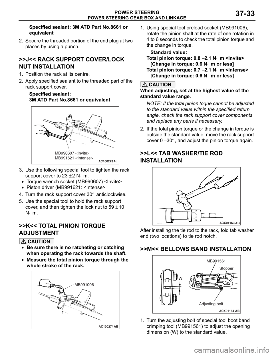
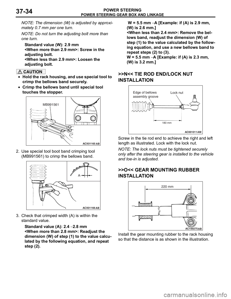
>>M<< BELLOWS BAND INSTALLATION
ACX01164 AB
W MB991561
Adjusting bolt Stopper
1. Turn the adjusting bolt of special tool boot band
crimping tool (MB991561) to adjust the opening
dimension (W) to the standard value.
Page 264 of 800
POWER STEERING GEAR BOX AND LINKAGE
POWER STEERING37-34
NOTE: The dimension (W) is adjusted by approxi-
mately 0.7 mm per one turn.
NOTE: Do not turn the adjusting bolt more than
one turn.
Standard value (W): 2.9 mm
adjusting bolt.
adjusting bolt.
CAUTION
•Hold the rack housing, and use special tool to
crimp the bellows band securely.
•
ACX01165AB
MB991561
Crimp the bellows band until special tool
touches the stopper.
2. Use special tool boot band crimping tool (MB991561) to crimp the bellows band.
ACX01166 AB
A
3. Check that crimped width (A) is within the
standard value.
Standard value (A): 2.4 − 2.8 mm
dimension (W) of step (1) to the value calcu
-
lated by the following equation, and repeat
step (2).
W = 5.5 mm − A [Example: if (A) is 2.9 mm,
(W) is 2.6 mm.]
lows band, readjust the dimension (W) of
step (1) to the value calculated by the follow
-
ing equation, and use a new bellows band to
repeat steps (2) to (3).
W = 5.5 mm − A [Example: if (A) is 2.3 mm,
(W) is 3.2 mm.]
>>N<< TIE ROD END/LOCK NUT
INSTALLATION
AC001011 AM
Lock nut
Edge of bellows
assembly groove
180 mm
Screw in the tie rod end to achieve the right and left
length as illustrated. Lock with the lock nut.
NOTE: The lock nuts must be tightened securely
only after the steering gear is installed to the vehicle
and toe-in is adjusted.
>>O<< GEAR MOUNTING RUBBER
INSTALLATION
AC100275 AB
220 mm
Install the gear mounting rubber to the rack housing
so that the distance is as shown in the illustration.
Page 265 of 800

POWER STEERING OIL PUMP ASSEMBLY
POWER STEERING37-35
TIE ROD END BALL JOINT DUST COVER
REPLACEMENT
M1372008200327
If the dust cover is damaged accidentally during
service work, replace the dust cover as follows:
AC001012AB
MB990776
1.App l y specified grea se to the lip an d inside of the
d u st c o ve r .
Specified grease:
Mu l t i p u r po se g r ea se SAE J3 10 , NL GI No .2 or
equival
ent
2.Drive in the d u st cover with special tool f r ont axle
b a se (MB9907 76) unt il it is fully seated .
3.Check t he dust co ver f o r cracks or da mage by
p u shing it with your finger .
POWER STEERING OIL PUMP ASSEMBL Y
REMOVA L AND INST ALLA TIONM13720052 0029 8
Pre-removal Operation
•Power Steering Fluid Draining (Refer to P.37-13).
Post-installation Operation
•Power Steering Fluid Supplying and Bleeding (Refer to
P.37-14).
•Drive Belt Tension Check (1300, 1600: refer to GROUP
11A, On-vehicle Service
− Drive Belt Tension Check
P.11A-7/2000: refer to GROUP 11C, On-vehicle Service − Drive Belt Tension Check P.11C-7).
<1300, 1600>
AC209708
87
1 2
3 4
5
6
57 ± 7 N·m
40 ± 4 N·m
22 ± 4 N·m
N
9
40 ± 5 N·m
AC
Page 266 of 800

Removal steps
1.Pressure switch connector
2.A/C compressor harness connector
bracket
3.Drive belt
4.Suction hose
5.Eye bolt
6.O-ring
7.Pressure hose
8.Oil pump assembly
9.Oil pump brace
POWER STEERING OIL PUMP ASSEMBLY
POWER STEERING37-36
<2000>
AC200116AB
22 ± 4 N·m
12 ± 2 N·m
22 ± 4 N·m
49 ± 9 N·m 57 ± 7 N·m
1
5
4
3
6
2
7
49 ± 9 N·m
Removal steps
1.Pressure switch connector
2.Drive belt
3.Suction hose
4.Pressure hose
<>5.Oil pump assembly
6.A/C compressor harness
7.Power steering pump bracket
REMOVA L SER VICE POINT
<> OIL PUMP ASSEMBL Y REMOV A L
<2000>
With the eng ine lif t ed by the jack, remove the o il
pump
assembly mounting b o lt (lower side) a t the pul
-
ley side .
INSPECTIONM13720053 0018 7
•Check the drive belt for cracks.
•Check th e pulley for une ven r o t a tion.
Remova l st ep s ( C ont inu e d)
Page 269 of 800
POWER STEERING OIL PUMP ASSEMBLY
POWER STEERING37-39
REASSEMBLY SERVICE POINTS
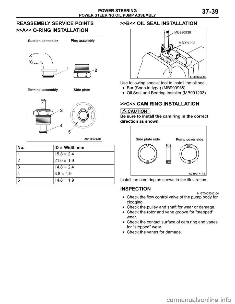
>>A<< O-RING INSTALLATION
AC100170AB
Suction connector Plug assembly
Terminal assembly Side plate
1 2
3
4 5
No.ID × Width mm
115.8 × 2.4
221.0 × 1.9
314.8 × 2.4
43.8 × 1.9
514.8 × 1.9
>>B<< OIL SEAL INST ALLA TION
AC000752
MB990938
AB
MB991203
Use following spe c ia l too l to inst all the oil seal.
•Bar (Snap-in type) (MB9909 38)
•Oil Seal and Bearin g Inst aller (MB9912 03)
>>C<< CAM RING INSTALLA TION
CAUTION
Be sure to install the cam ring in the correct
direction as shown.
AC100171AB
Side plate side
Pump cover side
Install the cam ring as shown in the illustration.
INSPECTION
M1372005500200
•Check the flow control valve of the pump body for
clogging.
•Check the pulley and shaft for wear or damage.
•Check the rotor and vane groove for "stepped"
wear.
•Check the contact surface of cam ring and vanes
for "stepped" wear.
•Check the vanes for damage.
Page 274 of 800
42-2
TROUBLESHOOTING . . . . . . . . . .42-26
ON-VEHICLE SERVICE. . . . . . . . .42-27
DOOR FIT ADJUSTMENT. . . . . . . . . . . 42-27
DOOR WINDOW GLASS
ADJUSTMENT . . . . . . . . . . . . . . . . . . . . 42-28
GLASS SLIDING MECHANISM CHECK
AND ADJUSTMENT . . . . . . . . . . . . . . . 42-28
POWER WINDOW OPERATING
CURRENT CHECK . . . . . . . . . . . . . . . . 42-28
POWER WINDOW RELAY CHECK . . . 42-29
CIRCUIT BREAKER (INCORPORATED
IN THE POWER WINDOW MOTOR)
INSPECTION . . . . . . . . . . . . . . . . . . . . . 42-29
POWER WINDOW CHECK . . . . . . . . . . 42-29
CENTRAL DOOR LOCKING SYSTEM
INSPECTION . . . . . . . . . . . . . . . . . . . . . 42-29
DOOR OUTSIDE HANDLE PLAY
CHECK . . . . . . . . . . . . . . . . . . . . . . . . . 42-29
DOOR INSIDE HANDLE PLAY
ADJUSTMENT . . . . . . . . . . . . . . . . . . . . 42-30
DOOR ASSEMBLY . . . . . . . . . . . .42-31
REMOVAL AND INSTALLATION . . . . . 42-31
INSPECTION . . . . . . . . . . . . . . . . . . . . . 42-32
DOOR GLASS AND REGULATOR42-32
REMOVAL AND INSTALLATION . . . . . 42-32
INSPECTION . . . . . . . . . . . . . . . . . . . . . 42-34
DOOR HANDLE AND LATCH . . . .42-36
REMOVAL AND INSTALLATION . . . . . 42-36
INSPECTION . . . . . . . . . . . . . . . . . . . . . 42-37
WINDOW GLASS RUNCHANNEL
AND DOOR OPENING
WEATHERSTRIP . . . . . . . . . . . . . .42-39
REMOVAL AND INSTALLATION . . . . . 42-39
TRUNK LID . . . . . . . . . . . . . . . .42-41
SPECIAL TOOL . . . . . . . . . . . . . . .42-41
ON-VEHICLE SERVICE. . . . . . . . .42-41
TRUNK LID ADJUSTMENT . . . . . . . . . . 42-41
ADJUSTMENT OF CLEARANCE
AROUND TRUNK LID . . . . . . . . . . . . . . 42-42
TRUNK LID STRIKER ADJUSTMENT . 42-42
TRUNK LID HEIGHT ADJUSTMENT . . 42-42
TRUNK LID . . . . . . . . . . . . . . . . . . .42-43
REMOVAL AND INSTALLATION . . . . . . 42-43
INSPECTION . . . . . . . . . . . . . . . . . . . . . 42-45
TAILGATE . . . . . . . . . . . . . . . . 42-46
SERVICE SPECIFICATIONS . . . . .42-46
SEALANTS . . . . . . . . . . . . . . . . . . .42-46
SPECIAL TOOL . . . . . . . . . . . . . . .42-46
TROUBLESHOOTING . . . . . . . . . .42-47
ON-VEHICLE SERVICE . . . . . . . . .42-47
TAILGATE FIT ADJUSTMENT. . . . . . . . 42-47
TAILGATE HANDLE PLAY CHECK . . . . 42-47
TAILGATE . . . . . . . . . . . . . . . . . . .42-48
REMOVAL AND INSTALLATION . . . . . . 42-48
TAILGATE HANDLE AND
LATCH . . . . . . . . . . . . . . . . . . . . . .42-50
REMOVAL AND INSTALLATION . . . . . . 42-50
INSPECTION . . . . . . . . . . . . . . . . . . . . . 42-51
KEYLESS ENTRY SYSTEM . . 42-51
SERVICE SPECIFICATIONS . . . . .42-51
SPECIAL TOOLS . . . . . . . . . . . . . .42-52
TROUBLESHOOTING . . . . . . . . . .42-53
ON-VEHICLE SERVICE . . . . . . . . .42-53
KEYLESS ENTRY SYSTEM CHECK. . . 42-53
KEYLESS ENTRY SYSTEM TIMER
LOCK FUNCTION INSPECTION . . . . . . 42-53
ENABLING/DISABLING THE
ANSWERBACK FUNCTION . . . . . . . . . 42-53
HOW TO REGISTER SECRET CODE . 42-55
TRANSMITTER. . . . . . . . . . . . . . . .42-58
DISASSEMBLY AND REASSEMBLY . . 42-58
INSPECTION . . . . . . . . . . . . . . . . . . . . . 42-59