check MITSUBISHI LANCER IX 2006 Service Manual
[x] Cancel search | Manufacturer: MITSUBISHI, Model Year: 2006, Model line: LANCER IX, Model: MITSUBISHI LANCER IX 2006Pages: 800, PDF Size: 45.03 MB
Page 367 of 800

REAR WIPER AND WASHER
EXTERIOR51-35
WINDSHIELD INTERMITTENT WIPER
VOLUME CHECK
1
6
8
11 10 9 7 5 4 3
2
AC201004
Ch
eck tha t the resist ance varie s between 0 a nd 1 kΩ
wh
en the
windshield int
e
rmittent volume is turn
ed
from F
A
ST
to SLOW by a
f
te
r mea
s
uring resist
an
ce
between conne
ctor
terminals 3 an
d 6 at
the column
switc
h
.
REAR WIPER AND W A SHER
GENERAL INFORMAT IONM151 1 0001 0052 5
REAR WIPER AND W A SHER OPERA T ION
Rear W i p e r O p eration
•If the rear wiper and washe r switch is turne d to
"INT" position
wit h th e ignition switch at "ACC" or
"ON" po
siti on, t he ET ACS-ECU t u rn s ON t he re ar
wipe
r drive signal for thre e se cond s (ap p roxi
-
mately two cycles), then 7 . 4 se cond s la ter the
int
e rmit tent mot i on o perates every eigh t seco nds.
If th
e se lector lever is moved to the "R" p o sition
when t
he rear wiper an d washe r switch is turn ed
to t
he "INT" position an d the ignit i on switch is at
the
"ACC" or "ON" positio n, the inhibito r switch "R" tu rns ON. One second late r , the ET ACS-ECU
turn s ON th e rear wip e r drive signal for thre e sec
-
ond
s (ap p roximat e ly two cycle s ). Th en, 7.4 sec-
onds later , th e inte rmittent motio n of eight
sec
o nds ' cy cle is restored.
Rear W a sher Operatio n
•If the rear wiper and washe r switch is turne d to
the
ON (washer) position wi th the ignition switch
at t
he "ACC" or "ON" po sit i on, t he rear wa sher
ON signal is sent to the ET
ACS-ECU, causing the
re
ar wipe r sign al to tu rn on a f ter 0 . 3 seco nd . Af te r
the
rear washer switch sign al tu rns o f f, the rear
wipe
r signa l t u rns of f in thre e seco nds. If the rear
washer switch is tu
rned to the ON position while
the
rear wipe r is in intermitten t mod e , the rear
washer works for th
at period when the washer
switch
rema ins on. Then the rea r wipe rs ret u rn to
the
intermitte nt mode.
SERV ICE SPECIFICA T ION
M151 1 0003 0033 6
ItemStandard value
Rear wiper blade park position mm42 ± 5
Page 368 of 800

REAR WIPER AND WASHER
EXTERIOR51-36
TROUBLESHOOTING
M1511000700334
The rear wiper and washer are controlled by the
Smart Wiring System (SWS). For troubleshooting,
refer to GROUP 54B, Troubleshooting
P.54B-15 or
GROUP 54C, Troubleshooting P.54C-4.
ON-VEHICLE SERVICE
M1511000800472
CHECK OF REAR WIPER OPERATION
WHEN SELECTOR LEVER IS AT THE "R"
POSITION
1. When the selector lever is moved to the "R" position with the rear wiper switch at the "INT"
position, the wiper should operate twice or three
times at low speed after approximately one
second.
2. If not, carry out the troubleshooting (Refer to GROUP 54B, Troubleshooting
P.54B-15 or
GROUP 54C, Troubleshooting P.54C-4).
REAR WIPER AND WASHER
REMOVAL AND INSTALLATIONM1511008500345
AC304515
2.5 ± 0.4 N·m
9.8 ± 2.0 N·m
7.4 ± 1.4 N·m
3 2
1
4
5
AB
Wiper blade assembly removal steps
>>A<<1.Wiper arm and blade assembly
>>B<<2.Wiper blade
Page 369 of 800

Rear wiper motor removal steps
•Tailgate trim lower (Refer to GROUP
52A, Tailgate trim
P.52A-21.)
•Tailgate waterproof film (Refer to
GROUP 42, Tailgate
P.42-48.)
3.Rear wiper motor assembly
Rear washer nozzle removal steps
•High-mounted stop lamp assembly
(Refer to GROUP 54A, High-mounted
stop lamp
P.54A-84.)
4.Rear washer nozzle
Washer hose removal steps
•Front scuff plate, rear scuff plate, cowl
side trim and quarter trim (Refer to
GROUP 52A, Trims
P.52A-13.)
•Tailgate lower trim, tailgate proof film
(Refer to GROUP 52A, Tailgate trim
P.52A-21.)
•High-mounted stop lamp assembly
(Refer to GROUP 54A, High-mounted
stop lamp
P.54A-84.)
5.Rear washer hose
REAR WIPE R AN D W A SHER
EXTERIOR51-37
NOTE: For re moval a nd in st allation of the wiper an d
washer switch, refer to GROUP 54A, Colu mn switch
P.5 4 A - 89.
INSTALLA T ION SER VICE POINT S
>>A<< REAR WIPER ARM AND BLADE
ASSEMBL
Y INST ALLA TION
AC304536
A
AC
End of tailgate glass
Before inst alling the rear wiper arm and blad e
assembly
, ope rate the rear wip e r mo tor so that th e
motor stop
s at the predete r min ed p a rk position .
Inst
all the re ar wipe arm a nd blade assembly and
adjust the
rear wipe r blad e positio n so t hat the blad e
end stop
s at the pre determined positio n (st anda rd
position
) .
St andard va lue (A): 42 ± 5 mm
>>B<< W I PER BLADE INST ALLA TION
AC101090AD
Wiper blade Backing
Backing A
A
Section A – A
Wiper
blade Backing
CAUTION
Use a curved backing like that shown for the
backing of a wiper blade to ensure sustained
wiper wiping performance.
INSPECTION
M1511008600193
REAR WIPER MOTOR CHECK
AB304538
1234
1234
1234
AB
(A) Operation check
(B) Stop position check
Inspect the rear wiper motor is conducted by remov-
ing the harness connector with the motor attached to
the vehicle.
Wiper Motor Operation
Connect the battery to the rear wiper motor as shown
in the illustration (A) and check the motor operation.
Wiper Motor at Stop Position Operation
1. Connect the battery to the rear wiper motor as
shown in the illustration (A).
Page 370 of 800
REAR WIPER AND WASHER
EXTERIOR51-38
2. Disconnect the battery cable from the rear windshield wiper motor while it is turning and then
check to see that the motor stops.
3. Re-connect the battery as shown in Figure (B).
4. Check to see that the rear windshield wiper motor runs and then stops at the automatic stop
position.
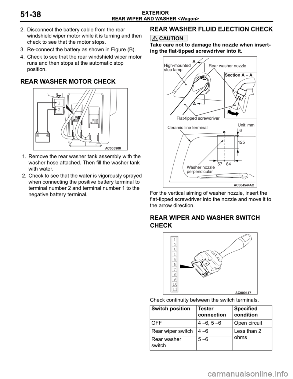
REAR WASHER MOTOR CHECK
1
2
AC005900
1.Remo ve th e rear washer t ank assembly with th e
wash er hose att a ched. T hen fill t he wash er t ank
with wa ter .
2.Check to see t hat t he wate r is vigor ously spra yed
when conn ecting the positive batt e ry te rmin al to
termina l number 2 and te rmin al nu mber 1 to th e
neg ative batt e ry te rmin al.
REAR WA SHER FLUI D EJECTION CHECK
CAUTION
Take care not to damage the nozzle when insert-
ing the flat-tipped screwdriver into it.
AC304544AC
Unit: mm
57 84 125
6
Section A – A
A
A
High-mounted
stop lamp Rear washer nozzle
Flat-tipped screwdriverCeramic line terminal
Washer nozzle
perpendicular
For the vertical aiming of washer nozzle, insert the
flat-tipped screwdriver into the nozzle and move it to
the arrow direction.
REAR WIPER AND WASHER SWITCH
CHECK
1
6
8
11 10 9 7
5 4
3
2
AC000417
Check continuity between the switch terminals.
Switch positionTester
connectionSpecified
condition
OFF4 − 6, 5 − 6Open circuit
Rear wiper switch4 − 6Less than 2
ohms
Rear washer
switch5 − 6
Page 372 of 800

HEADLAMP WASHER
EXTERIOR51-40
INSPECTION
M1511009800082
HEADLAMP WASHER MOTOR CHECK
AC304136AB
12
1.Remove the he adla m p washer motor connector .
2.Check to se e tha t the wat e r is vigorou sly sp rayed
when con nect i ng th e positive ba ttery terminal to
te rmin al nu mber 1 and terminal n u mb er 2 to the
n egative ba ttery terminal.
8.Headlamp wa s h er gasket
•Fr o n t b u m p er ( R ef er to P.51-3).
9.Head lam p wa sh er a c tu ator
assembly
10.O-rin g
11.Headlamp w a s h er hose assembly
Remo val st ep s ( C o n tinue d)
Page 376 of 800

DOOR MIRROR
EXTERIOR51-44
SYMPTOM PROCEDURES
Inspection Procedure 1: All Heated Door Mirrors do not Operate
Wire colour code
B : Black LG : Light green G : Green L : Blue W : White \
Y : Yellow SB : Sky blue
BR : Brown O : Orange GR : Gray R : Red P : Pink V :\
Violet REAR WINDOW
DEFOGGER RELAY
REAR WINDOW
DEFOGGER
REMOTE
CONTROLLED
MIRROR (LH)
REMOTE
CONTROLLED
MIRROR (RH)
MIRROR
HEATER MIRROR
HEATER
NOTELH drive vehicles
RH drive vehicles
COMM
ENT S ON TROUBL E SYMPT O M
The heated do or mirrors shou ld works for approxi-
mately 11 minu tes whe n the re ar defo gger switch is
turned o
n . If th e mirror hea ter doe s no t work fo r the
specified period, th
e defo gger relay circuit (heated
door mirror p
o wer sup p ly circuit) may be d e fective .
PROBABLE CAUSE
•Damaged h a rness wire and connector
DIAGNOSIS PROCEDURE
STEP 1 . Check the rear wind ow de fogger .
Check that th e rear window def ogger system shou ld
wo
rk normally .
Q:Is t h e che c k r esu lt n o rmal?
YES : Go to S t ep 2 .
NO : Tr oublesh oot the rear win dow defog ger
(Refer to
GROUP 55 ,
T
r oublesh ootin g
P.55B-54).
Page 377 of 800
DOOR MIRROR
EXTERIOR51-45
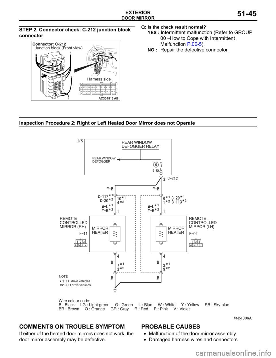
STEP 2. Connector check: C-212 junction block
connector
AC304913
21716151718
201912345
623 222425282627981011141213
Connector: C-212
Harness side
AB
Junction block (Front view)
Q: Is t h e che c k r esu lt n o rmal?
YES : Intermittent malfun ctio n (Refer to GROUP
00
− Ho w to Cope wit h Intermitte nt
Ma
lfunction
P.00-5).
NO : Repa ir th e defective connector .
Inspection Procedure 2 : Ri ght or Lef t Hea t ed Door Mirror does not Operate
Wire colour code
B : Black LG : Light green G : Green L : Blue W : White \
Y : Yellow SB : Sky blue
BR : Brown O : Orange GR : Gray R : Red P : Pink V :\
Violet REAR WINDOW
DEFOGGER RELAY
REAR WINDOW
DEFOGGER
REMOTE
CONTROLLED
MIRROR (LH)
REMOTE
CONTROLLED
MIRROR (RH)
MIRROR
HEATER MIRROR
HEATER
NOTELH drive vehicles
RH drive vehicles
COMM
ENT S ON TROUBL E SYMPT O M
If eit her of t he hea ted d oor mirrors does n o t work, the
door mirror a
sse mbly may b e defe c tive.
PROBABLE CAUSES
•Malfunctio n of th e door mirro r assemb ly
•Damaged ha rness wires and con necto rs
Page 378 of 800
DOOR MIRROR
EXTERIOR51-46
DIAGNOSIS PROCEDURE
STEP 1. Verify the operation of each heated door
mirror.
Q: Which door mirror does not heat?
Door mirror (RH) : Go to Step 2.
Door mirror (LH) : Go to Step 9.
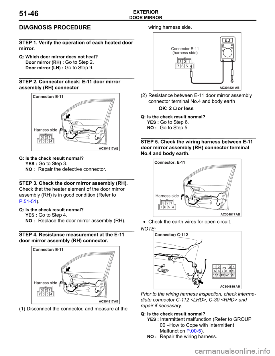
STEP 2. Connector check: E-11 door mirror
assembly (RH) connector
AC304817
Connector: E-11Harness side
AB
Q : Is the check result normal?
YES : Go to S t ep 3.
NO : Repa ir the defective connector .
STEP 3. Ch eck the door mirror assem bly (RH).
Chec k that th e heat er ele m ent of the door mirror
assembly (RH) is in
good condition (Refer to
P.5 1 -51).
Q: Is the check result normal?
YES : Go to S t ep 4.
NO : Replac e th e door mirro r assemb ly ( R H).
STEP 4. Re sist an ce mea surement at the E-1 1
door mirror
assem bly (RH) connec tor .
AC304817
Connector: E-11
Harness side
AB
(1) D isconn ect t he co nnector , an d me asure at the wiring harn e ss side.
AC304821
Connector E-11
(harness side)
AB
(2) R esist ance bet we en E-1 1 door mirro r assemb ly
connector termina l No.4 a nd bod y ea rth
OK: 2 Ω or less
Q:Is t h e che c k r esu lt n o rmal?
YES : Go to S t ep 6 .
NO : Go to S t ep 5.
STEP 5 . Check the wiring harness b e twee n E-1 1
door mirror assem
bly (RH) conne ctor terminal
No.
4 and bo dy earth.
AC304817
Connector: E-11
Harness side
AB
•Check th e earth wires f o r open circuit.
NOTE:
AC304819
Connector: C-112
AB
Prior to the wiring harness insp ection, check interme-
diate connector C-1 1 2
rep
a ir if necessary .
Q:Is t h e che c k r esu lt n o rmal?
YES : Intermittent malfun ctio n (Refer to GROUP
00
− Ho w to Cope wit h Intermitte nt
Ma
lfunction
P.00-5).
NO : Repa ir th e wirin g harne ss.
Page 379 of 800
DOOR MIRROR
EXTERIOR51-47
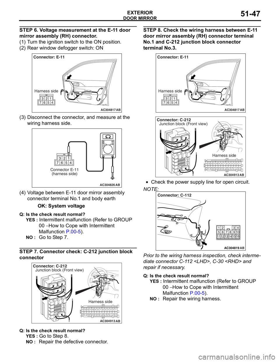
STEP 6. Voltage measurement at the E-11 door
mirror assembly (RH) connector.
(1) Turn the ignition switch to the ON position.
(2) Rear window defogger switch: ON
AC304817
Connector: E-11Harness side
AB
(3) D isconn ect t he co nnector , an d me asure at the
wiring harn e ss side.
AC304826
Connector E-11(harness side)
AB
(4) V olt a g e between E-1 1 door mirror assembly
co nnector termina l No.1 a nd bod y ea rth
OK: System vo lt age
Q: Is the check result normal?
YES : Intermittent ma lfun ctio n (Refer to GROUP
00
− Ho w t o Cope wit h Intermitte nt
Malfunction
P.00-5).
NO : Go to S t ep 7.
STEP 7. Co nnector ch eck: C-212 junction block
connecto
r
AC304913
21716151718
201912345
623 222425282627981011141213
Connector: C-212
Harness side
AB
Junction block (Front view)
Q : Is the check result normal?
YES : Go to S t ep 8.
NO : Repa ir the defective connector .
STEP 8 . Check the wiring harness b e twee n E-1 1
door mirror assem
bly (RH) conne ctor terminal
No.
1 and C-21 2 junctio n block connec tor
terminal No.3
.
AC304817
Connector: E-11
Harness side
AB
AC304913
21716151718
201912345
623 222425282627981011141213
Connector: C-212
Harness side
AB
Junction block (Front view)
•Check th e power supply line fo r open circuit.
NOTE:
AC304819
Connector: C-112
AB
Prior to the wiring harness insp ection, check interme-
diate connector C-1 1 2
rep
a ir if necessary .
Q:Is t h e che c k r esu lt n o rmal?
YES : Intermittent malfun ctio n (Refer to GROUP
00
− Ho w to Cope wit h Intermitte nt
Ma
lfunction
P.00-5).
NO : Repa ir th e wirin g harne ss.
Page 380 of 800
DOOR MIRROR
EXTERIOR51-48
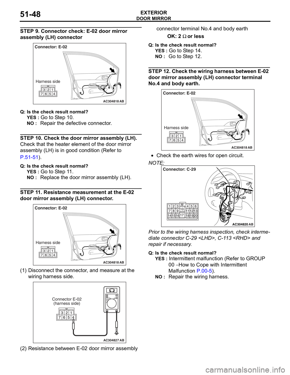
STEP 9. Connector check: E-02 door mirror
assembly (LH) connector
AC304818
Connector: E-02Harness side
AB
Q : Is the check result normal?
YES : Go to S t ep 10 .
NO : Repa ir the defective connector .
STEP 10 . Check th e door mirror asse mbly (L H).
Chec k that th e heat er ele m ent of the door mirror
assembly (L
H) is in goo d con d ition (Refer to
P.5 1 -51).
Q: Is the check result normal?
YES : Go to S t ep 1 1 .
NO : Replac e th e door mirro r assemb ly ( L H) .
STEP 11 . Resist ance m easureme n t at the E-0 2
door mirror
assem bly (LH) con nector .
AC304818
Connector: E-02
Harness side
AB
(1) D isconn ect t he co nnector , an d me asure at the
wiring harn e ss side.
AC304827
Connector E-02(harness side)
AB
(2) R esist ance betwee n E-02 do or mirror assembly connector termina l No.4 a nd bod y ea rth
OK
: 2 Ω or less
Q:Is t h e che c k r esu lt n o rmal?
YES : Go to S t ep 1 4 .
NO : Go to S t ep 12 .
STEP 1 2 . Chec k the wiring ha rnes s betwe en E-02
door mirror assem
bly (LH) con nector termina l
No.
4 and bo dy earth.
AC304818
Connector: E-02
Harness side
AB
•Check th e earth wires f o r open circuit.
NOTE:
AC304820
Connector: C-29
AB
Prior to the wiring harness insp ection, check interme-
diate connector C-29
rep
a ir if necessary .
Q:Is t h e che c k r esu lt n o rmal?
YES : Intermittent malfun ctio n (Refer to GROUP
00
− Ho w to Cope wit h Intermitte nt
Ma
lfunction
P.00-5).
NO : Repa ir th e wirin g harne ss.