MITSUBISHI LANCER IX 2006 User Guide
Manufacturer: MITSUBISHI, Model Year: 2006, Model line: LANCER IX, Model: MITSUBISHI LANCER IX 2006Pages: 800, PDF Size: 45.03 MB
Page 11 of 800
ON-VEHICLE SERVICE
ENGINE LUBRICATION12-5
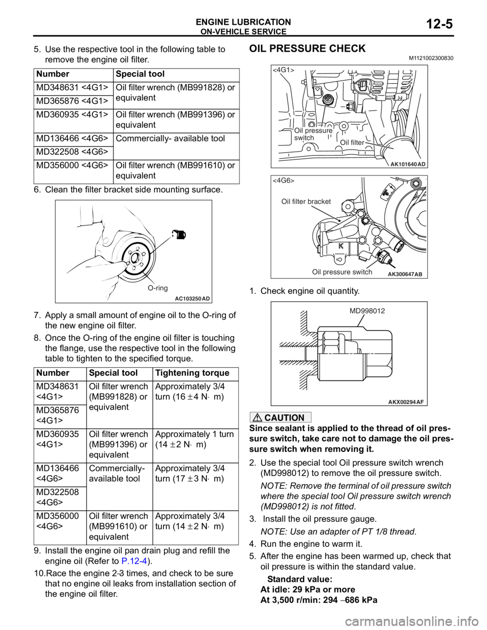
5. Use the respective tool in the following table to remove the engine oil filter.
NumberSpecial tool
MD348631 <4G1>Oil filter wrench (MB991828) or
equivalent
MD365876 <4G1>
MD360935 <4G1>Oil filter wrench (MB991396) or
equivalent
MD136466 <4G6>Commercially- available tool
MD322508 <4G6>
MD356000 <4G6>Oil filter wrench (MB991610) or
equivalent
6. Cle an the filt er bracket side mou n ting surfa c e.
AC103250AD
O-ring
7.Ap ply a small a m ou nt o f en gine o i l to th e O-rin g of
th e new eng ine oil f ilte r .
8.Once the O-ring of the engine oil filter is tou c hing
th e flange, use the resp ective tool in the following
t able to tighten to the specified tor que.
NumberSpecial toolTightening torque
MD348631
<4G1>Oil filter wrench
(MB991828) or
equivalentApproximately 3/4
turn (16
± 4 N⋅m)
MD365876
<4G1>
MD360935
<4G1>Oil filter wrench
(MB991396) or
equivalentApproximately 1 turn
(14
± 2 N⋅m)
MD136466
<4G6>Commercially-
available toolApproximately 3/4
turn (17
± 3 N⋅m)
MD322508
<4G6>
MD356000
<4G6>Oil filter wrench
(MB991610) or
equivalentApproximately 3/4
turn (14
± 2 N⋅m)
9.In st all the en gine oil p a n drain plu g and refill the
en gine oil (Re f er to
P.12-4).
10.Race the en gine 2−3 times, and che ck to be sure
th
at n
o
en
gin
e
oil leaks fr om in st allation sectio n of
th
e engine oil filter
.
OIL PRESSURE CHECK
M1 121 0023 0083 0
AK101640
<4G1>
Oil pressure
switch
Oil filter
AD
AK300647
AB
<4G6>
Oil filter bracket
Oil pressure switch
1.Check e ngin e oil quan tity .
AKX00294
MD998012
AF
CAUTION
Since sealant is applied to the thread of oil pres-
sure switch, take care not to damage the oil pres-
sure switch when removing it.
2. Use the special tool Oil pressure switch wrench
(MD998012) to remove the oil pressure switch.
NOTE: Remove the terminal of oil pressure switch
where the special tool Oil pressure switch wrench
(MD998012) is not fitted.
3. Install the oil pressure gauge.
NOTE: Use an adapter of PT 1/8 thread.
4. Run the engine to warm it.
5. After the engine has been warmed up, check that oil pressure is within the standard value.
Standard value:
At idle: 29 kPa or more
At 3,500 r/min: 294 − 686 kPa
Page 12 of 800
ON-VEHICLE SERVICE
ENGINE LUBRICATION12-6
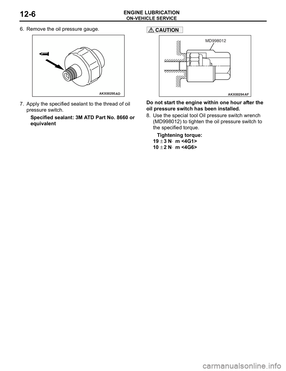
6. Remove the oil pressure gauge.
AKX00295AD
7.App l y t he sp ecified sealant to the thr ead of oil
pres sure sw itc h .
Specified sealan t: 3M A T D Part No. 8660 or
equival
ent
AKX00294
MD998012
AF
CAUTION
Do not start the engine within one hour after the
oil pressure switch has been installed.
8. Use the special tool Oil pressure switch wrench (MD998012) to tighten the oil pressure switch to
the specified torque.
Tightening torque:
19 ± 3 N⋅m <4G1>
10 ± 2 N⋅m <4G6>
Page 13 of 800
13-1
GROUP 13
FUEL
CONTENTS
MULTIPORT FUEL INJECTION (MPI) <4G1> . . . . . . . . . . . . . .13A
MULTIPORT FUEL INJECTION (MPI) <4G6> . . . . . . . . . . . . . .13B
FUEL SUPPLY . . . . . . . . . . . . . . . . . . . . . . . . . . . . . . . . . . . . . .13C
Page 14 of 800

NOTES
Page 15 of 800
14-1
GROUP 14
ENGINE COOLING
CONTENTS
GENERAL INFORMATION . . . . . . . .14-2
SERVICE SPECIFICATIONS . . . . . . .14-2
LUBRICANT . . . . . . . . . . . . . . . . . . . .14-3
SEALANTS . . . . . . . . . . . . . . . . . . . .14-3
SPECIAL TOOLS . . . . . . . . . . . . . . . .14-3
TROUBLESHOOTING . . . . . . . . . . . .14-5
INSPECTION CHART FOR TROUBLE
SYMPTOMS . . . . . . . . . . . . . . . . . . . . . . . . 14-5
INSPECTION PROCEDURE FOR
TROUBLE SYMPTOMS . . . . . . . . . . . . . . . 14-6
ON-VEHICLE SERVICE . . . . . . . . . . .14-21
ENGINE COOLANT LEAK CHECK . . . . . . 14-21
RADIATOR CAP VALVE OPENING
PRESSURE CHECK . . . . . . . . . . . . . . . . . . 14-21
ENGINE COOLANT REPLACEMENT . . . . 14-21
CONCENTRATION MEASUREMENT . . . . 14-22
COOLING FAN MOTOR DRIVE
CONTROL UNIT CHECK . . . . . . . . . . . . . . 14-22
FAN CONTROL RELAY CONTINUITY
CHECK . . . . . . . . . . . . . . . . . . . . . . . . . . . . 14-23
COOLING FAN MOTOR CHECK . . . . . . . . 14-24
THERMOSTAT . . . . . . . . . . . . . . . . . .14-24
REMOVAL AND INSTALLATION . . . . . . . . 14-24
INSPECTION. . . . . . . . . . . . . . . . . . . . . . . . 14-26
WATER PUMP . . . . . . . . . . . . . . . . . .14-27
REMOVAL AND INSTALLATION <4G1> . . 14-27
REMOVAL AND INSTALLATION <4G6> . . 14-28
WATER HOSE AND WATER PIPE . .14-29
REMOVAL AND INSTALLATION <4G1> . . 14-29
REMOVAL AND INSTALLATION <4G6> . . 14-31
INSPECTION. . . . . . . . . . . . . . . . . . . . . . . . 14-32
RADIATOR . . . . . . . . . . . . . . . . . . . . .14-33
REMOVAL AND INSTALLATION <4G1> . . 14-33
REMOVAL AND INSTALLATION <4G6> . . 14-35
Page 16 of 800

GENERAL INFORMATION
ENGINE COOLING14-2
GENERAL INFORMATION
M1141000100371
The cooling system is designed to keep every part of
the engine at appropriate temperature in whatever
condition the engine may be operated. The cooling
method is of the water-cooled, pressure forced circu
-
lation type in which the water pump pressurizes cool-
ant and circulates it throughout the engine. If the
coolant temperature exceeds the prescribed temper
-
ature, the thermostat opens to circulate the coolant
through the radiator as well so that the heat
absorbed by the coolant may be radiated into the air.
The water pump is of the centrifugal type and is
driven by the alternator drive belt from the crank
-
shaft. The radiator is the corrugated fin, down flow
type.
ItemSpecification
RadiatorPerformance kJ/h4G13Standard vehicles137,720
Vehicles with capacity up radiator
(option)161,288
4G18Standard vehicles161,288
Vehicles with capacity up radiator
(option)181,800
4G63181,800
A/T oil coolerPerformance kJ/h5,651
SERVICE SPECIFICATIONS
M1141000300687
ItemStandard valueLimit
Fan controller VA/C OFF1 or less-
A/C ONRepeat
8.2 ± 0.7
System voltage ± 2.6
-
High-pressure valve opening pressure of radiator cap kPa93 − 123Minimum 83
Range of coolant antifreeze concentration of radiator %30 − 60-
ThermostatValve opening temperature of
thermostat
°C
4G188 ± 1.5-
4G682 ± 1.5-
Full-opening temperature of
thermostat
°C
4G1100-
4G695-
Valve lift mm8.5 or more-
Page 17 of 800
LUBRICANT
ENGINE COOLING14-3
LUBRICANT
M1141000400338
ItemSpecified coolantQuantity L
Engine coolant (including
condense tank)DIAQUEEN SUPER LONG LIFE COOLANT
or an equivalent4G15.0
4G67.0
SEALANTS
M1141000500324
ItemSpecified sealant
Cylinder block drain plug3M Nut Locking Part No.4171 or equivalent
Water pump <4G1>, Thermostat case
<4G6>, Cooling water outlet hose fitting
<4G6>MITSUBISHI GENUINE Part No.MD970389 or equivalent
SPECIAL TOOLS
M1141000600581
ToolNumberNameUse
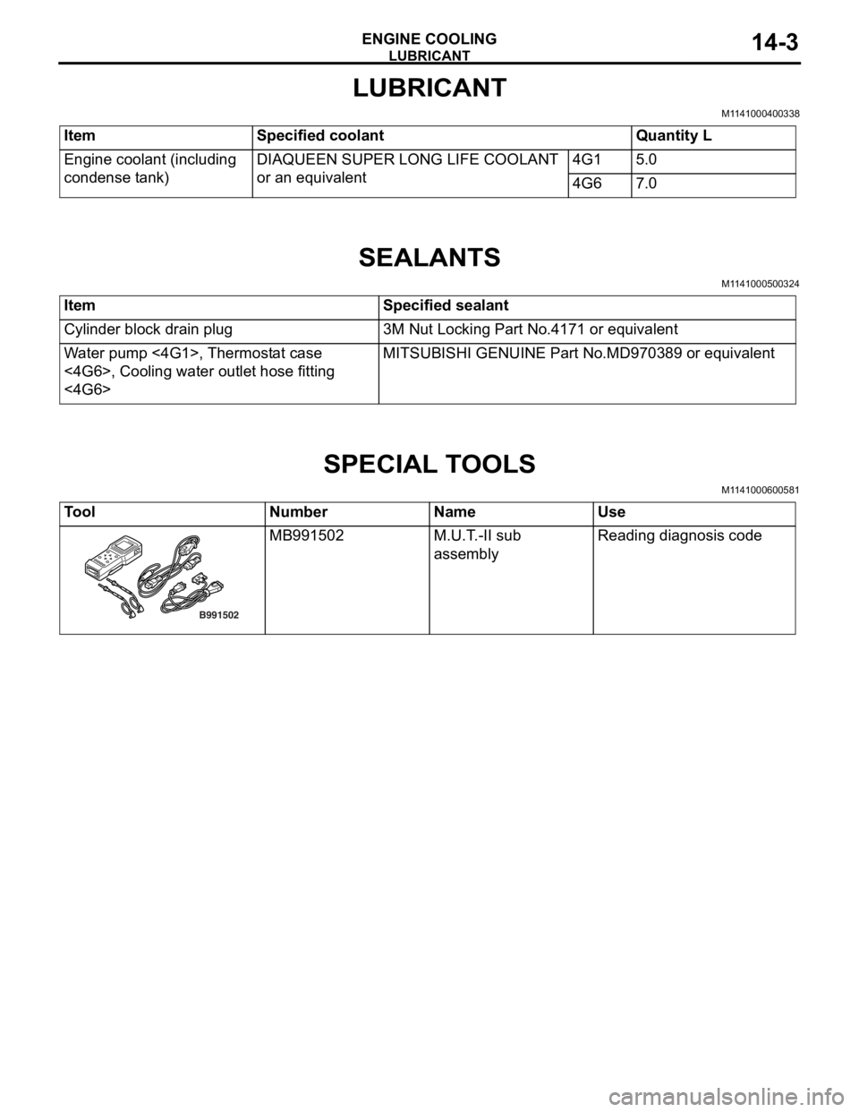
B991502
MB991502M.U.T. -II sub
assemblyReading diagno sis co de
Page 18 of 800
MB991910
MB991826MB991955
MB991911
MB991824
MB991827
MB991825
A
B C
D
E F
DO NOT USE
S PECIA L T O OLS
ENGINE COOLING14-4
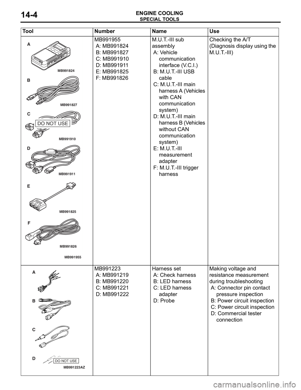
MB991 955
A: MB9918 24
B: MB991827
C: MB99191 0
D: MB991911
E: MB991825
F: MB991 826
M.U.T. -III su b
assembly
A: Ve hicle
communication
interface (V .C.I.)
B: M.U.T. -III US B
cable
C: M.U.T . -III main
ha rn es s A (V e h i c le s
with CA N
communication
sy stem )
D: M.U.T. -III main
ha rn es s B (V e h i c le s
wit hout CAN
communication
sy stem )
E: M.U.T. -III
measureme n t
ad apter
F: M.U.T . -III trig ger
ha rness
Checkin g the A/T
(D
ia gn osis d i sp lay using t h e
M.U.
T . -III)
MB991223
A
D C
B
AZ
DO NOT USE
MB991 223
A: MB9912 19
B: MB991220
C: MB99122 1
D: MB991222
Harness se t
A: Check h a rnes s
B: LE D ha rness
C: LED ha rness
ad apter
D: Probe
Making vo lt age an d
resist
an ce measureme n t
during tro
uble s hoo ting
A: Connector pin cont act
pressure inspect i on
B: Power circuit inspection
C: Power circuit inspection
D: Commercial tester
con nect i on
Tool Nu mber Na me Use
Page 19 of 800
MB992006
TROUBLESHOOTING
ENGINE COOLING14-5
TROUBLESHOOTI N G
INSPECTION CHAR T FOR TROUBLE
SYMPT
O MS
M1141 0056 0036 0
Trouble symptomInspection
procedure No.Reference page
Cooling fan (L.H.) and Cooling fan (R.H.) <4G1 (Vehicles with
A/C)> or A/C condenser fan <4G6> do not operate 1P.14-6
Cooling fan (L.H.) and Cooling fan (R.H.) <4G1 (Vehicles with
A/C)> or A/C condenser fan <4G6> do not change speed or stop2P.14-16
Cooling fan (L.H.) does not operate {When cooling fan (R.H.)
<4G1> or A/C condenser fan <4G6> operate}
Cooling fan (R.H.) <4G1> or A/C condenser fan <4G6> does not
operate {When cooling fan (L.H.) operate}
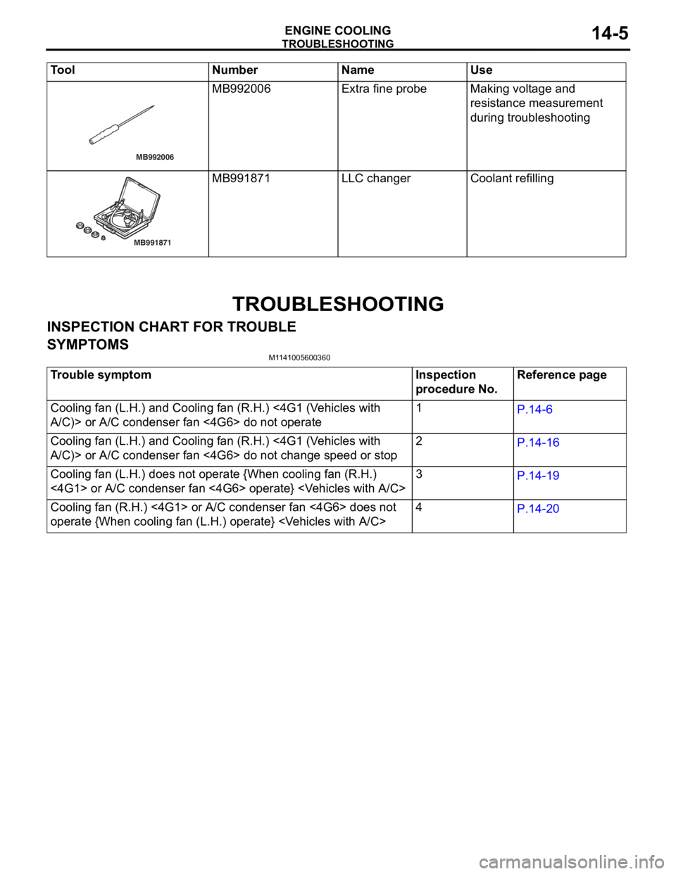
MB992006Extra fine pro b eMaking volt age an d
resist
an ce measureme n t
during tro
uble s hoo ting
MB991871
MB991871LLC cha ngerCoolant refilling
Tool Nu mber Na me Use
Page 20 of 800

TROUBLESHOOTING
ENGINE COOLING14-6
INSPECTION PROCEDURE FOR
TROUBLE SYMPTOMS
INSPECTION PROCEDURE 1: Cooling Fan (L.H.) and Cooling Fan (R.H.) <4G1 (Vehicles with A/C)> or
A/C Condenser Fan <4G6> do not Operate
Wire colour code
B : Black LG : Light green
G : Green L : Blue
W : White Y : Yellow
SB : Sky blue BR : Brown
O : Orange GR : Gray
R : Red P : Pink V : Violet
FAN CONTROL
RELAY
A-09XENGINE CONTROL
RELAY
B-16X
AC303577
A-18-1
COOLING FAN
MOTOR (L.H.)
COOLING FAN
MOTOR (R.H.)
<4G1 (VEHICLES
WITH A/C>
OR
A/C CONDENSER
FAN MOTOR <4G6> A-18-2
A-18
COOLING FAN
MOTOR DRIVE
CONTROL UNIT 1 A-13
12 C-111
ENGINE-ECU
ENGINE-A/T-ECU
21 C-123
18 C-122
615 121179
810234
(MU802322)
(MU801824)
C-123
(MU803784)C-122
(MU802611)A-13
C-111 L
L 2
22 11
1B
L
2
3
4
B-W
FUSIBLE
LINK No.2
B3
1
R-Y
R-Y
8 A-13
11 C-111
615 121179
810234
(MU802611)
J/C (6)
C-12
C-134
R-Y
3328
A-13
C-111
Cooling Fan (L.H.) and Cooling Fan (R.H.) or A/C Condenser Fan Drive Circut
AB
CIRCUIT OPERA T ION
•The cooling fan motor drive contro l unit is pow-
ered from fusible link (2).
•The engine-ECU
water t
e mpe r ature sensor unit and the vehicle
speed sensor
senso
r to control the speed of the coo ling
fan
moto r (L.H.) and the cooling fa n mot o r (R.H.)
<4G1 (V
ehicles wit h A/C)> or A/C co ndenser fan
motor <4G6>.