MITSUBISHI LANCER IX 2006 Service Manual
Manufacturer: MITSUBISHI, Model Year: 2006, Model line: LANCER IX, Model: MITSUBISHI LANCER IX 2006Pages: 800, PDF Size: 45.03 MB
Page 231 of 800
37-1
GROUP 37
POWER STEERING
CONTENTS
GENERAL INFORMATION . . . . . . . .37-3
SERVICE SPECIFICATIONS . . . . . . .37-6
LUBRICANTS . . . . . . . . . . . . . . . . . .37-7
SEALANTS . . . . . . . . . . . . . . . . . . . .37-7
SPECIAL TOOLS . . . . . . . . . . . . . . . .37-8
ON-VEHICLE SERVICE . . . . . . . . . . .37-11
STEERING WHEEL FREE PLAY CHECK . 37-11
STEERING ANGLE CHECK . . . . . . . . . . . . 37-11
TIE ROD END BALL JOINT TURNING
TORQUE CHECK . . . . . . . . . . . . . . . . . . . . 37-12
STATIONARY STEERING EFFORT
CHECK . . . . . . . . . . . . . . . . . . . . . . . . . . . . 37-12
STEERING WHEEL RETURN TO
CENTRE CHECK . . . . . . . . . . . . . . . . . . . . 37-13
DRIVE BELT TENSION CHECK. . . . . . . . . 37-13
FLUID LEVEL CHECK . . . . . . . . . . . . . . . . 37-13
FLUID REPLACEMENT . . . . . . . . . . . . . . . 37-13
POWER STEERING SYSTEM AIR
BLEEDING . . . . . . . . . . . . . . . . . . . . . . . . . 37-14
OIL PUMP PRESSURE TEST . . . . . . . . . . 37-14
POWER STEERING PRESSURE
SWITCH CHECK . . . . . . . . . . . . . . . . . . . . . 37-15
TIE ROD END BALL JOINT DUST
COVER CHECK . . . . . . . . . . . . . . . . . . . . . 37-15
STEERING COLUMN SHAFT ASSEMBLY
SHOCK ABSORBING MECHANISM
CHECK . . . . . . . . . . . . . . . . . . . . . . . . . . . . 37-15
STEERING WHEEL . . . . . . . . . . . . . .37-17
REMOVAL AND INSTALLATION
REMOVAL AND INSTALLATION
Continued on next page
WARNINGS REGARDING SERVICING OF SUPPLEMENTAL RESTRAINT SYSTEM (SRS) EQUIPPED VEHICLES
WARNING
•Improper service or maintenance of any component of the SRS, or any SRS-related component, can lead to
personal injury or death to service personnel (from inad vertent firing of the air bag) or to the driver and
paassenger (from renderin g the SRS inoperative).
•Service or maintenance of any SRS component or SRS-related component must be performed only at an
authorized MITSUBISHI dealer.
•MITSUBISHI dealer personnel must thoroughly review th is manual, and especially its GROUP 52B - Supplemental
Restraint System (SRS) before begi nning any service or maintenance of any component of the SRS or any
SRS-related component.
NOTE
The SRS includes the following components: SRS air bag control unit, SRS warning light, front impact sensors, air bag module,
clock spring, and interconnecting wiring. Other SRS-related components (that may have to be removed/installed in connection
with SRS service or maintenance) are indicated in the table of contents by an asterisk (*).
Page 232 of 800
37-2
STEERING COLUMN SHAFT
ASSEMBLY . . . . . . . . . . . . . . . . . . . .37-20
REMOVAL AND INSTALLATION . . . . . . . . 37-20
DISASSEMBLY AND REASSEMBLY . . . . . 37-22
POWER STEERING GEAR BOX AND
LINKAGE . . . . . . . . . . . . . . . . . . . . . .37-23
REMOVAL AND INSTALLATION . . . . . . . . 37-23
INSPECTION . . . . . . . . . . . . . . . . . . . . . . . 37-24
DISASSEMBLY AND REASSEMBLY . . . . . 37-26
TIE ROD END BALL JOINT DUST COVER
REPLACEMENT . . . . . . . . . . . . . . . . . . . . . 37-35
POWER STEERING OIL PUMP
ASSEMBLY. . . . . . . . . . . . . . . . . . . . .37-35
REMOVAL AND INSTALLATION . . . . . . . . 37-35
INSPECTION. . . . . . . . . . . . . . . . . . . . . . . . 37-36
DISASSEMBLY AND REASSEMBLY . . . . . 37-37
INSPECTION. . . . . . . . . . . . . . . . . . . . . . . . 37-39
POWER STEERING HOSES . . . . . . .37-40
REMOVAL AND INSTALLATION . . . . . . . . 37-40
Page 233 of 800

GENERAL INFORMATION
POWER STEERING37-3
GENERAL INFORMATION
M1372000100661
Power steering has been adopted in all vehicles to
make the steering system easier to handle.
FEATURES
•A 4-spoke steering wheel is used.
•MOMO leather-wrapped 3-spoke steering wheel
is used.
•A steering column has a shock absorbing mecha-
nism and a tilt steering mechanism.
•Integral-type rack and pinion gear with high rigid-
ity and excellent response is used.
•A vane type pump with a fluid flow rate control
system which change steering effort according to
the engine speed is used.
•The separate plastic resin oil reservoir is used to
reduce weight and to make the fluid level check
-
ing easier.
SPECIFICATIONS
ItemInviteIntense
Steering
wheelTy p e4-spoke typeMOMO leather-wrapped
3-spoke type
Outside diameter mm380365
Maximum number of turns3.193.08
Steering
columnColumn mechanismShock absorbing mechanism and Tilt steering mechanism
Power steering typeIntegral type
Oil pumpTy p eVane pump
Basic discharge amount cm3/rev.7.2 <1300, 1600>
8.1 <2000>
7.2 <1300, 1600>
8.1 <2000>
Relief pressure MPa8.88.8
Reservoir typeSeparate type (plastic)
Pressure switchEquipped
Steering
gearTy p eRack and pinion
Stroke ratio (Rack stroke/Steering
wheel maximum turning radius)45.7445.74
Rack stroke mm146141
Page 234 of 800
GENERAL INFORMATION
POWER STEERING37-4
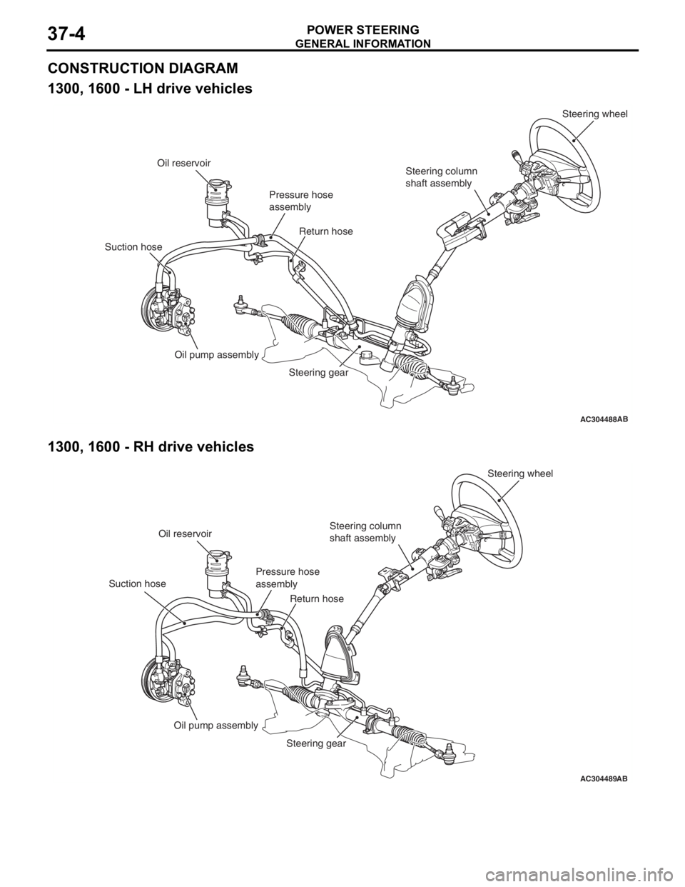
CONSTRUCTION DIAGRAM
1300, 1600 - LH drive vehicles
AC304488AB
Steering wheel
Steering column
shaft assembly
Pressure hose
assembly
Oil reservoir
Suction hose Return hose
Oil pump assembly Steering gear
1300, 1600 - RH drive vehicl es
AC304489AB
Steering wheel
Steering column
shaft assembly
Pressure hose
assembly
Oil reservoir
Suction hose Return hose
Oil pump assembly Steering gear
Page 235 of 800
GENERAL INFORMATION
POWER STEERING37-5
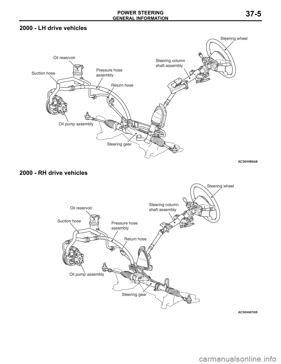
2000 - LH drive vehicles
AC304486AB
Steering wheel
Steering column
shaft assembly
Pressure hose
assembly
Oil reservoir
Suction hose Return hose
Oil pump assembly Steering gear
2000 - RH drive vehicles
AC304487AB
Steering wheel
Steering column
shaft assembly
Pressure hose
assembly
Oil reservoir
Suction hose
Return hose
Oil pump assembly Steering gear
Page 236 of 800

SERVICE SPECIFICATIONS
POWER STEERING37-6
SERVICE SPECIFICATIONS
M1372000300795
ItemStandard valueLimit
Steering wheel free
play mmWith engine running−30
With engine stopped10 or less−
Steering angleInner wheelInvite39°30' ± 1°30'−
Intense (LH drive vehicles)33°40' +1°00'/-2°00'−
Intense (RH drive vehicles)37°00' +1°00'/-2°00'−
Outer wheel
(reference)Invite32°30'−
Intense (LH drive vehicles)28°46'−
Intense (RH drive vehicles)30°00'−
Toe-inAt the centre of tyre tread mm1 ± 2−
Toe-angle (per wheel)0°03' ± 06'−
Tie rod end ball joint turning torque N⋅m0.5 − 2.5−
Tie rod swing resistance N [Tie rod swing torque N⋅m]8 − 27 [1.5 − 4.9]−
Stationary steering effort N [Fluctuation allowance N]29 or less [5.9 or less]−
Oil pump pressure
MPa (750
± 100 r/min.)
Oil pump relief pressure8.8 − 9.5−
Pressure under no-load conditions0.2 − 0.7−
Steering gear retention hydraulic pressure8.8 − 9.5−
Oil pressure switch operating pressure
MPaOFF → ON1.5 − 2.0−
ON → OFF0.7 − 2.0−
Steering gear total pinion torque N⋅m
[Change in torque N
⋅m]
Invite0.8 − 2.1 [0.6 or less]−
Intense0.7 − 2.1 [0.6 or less]−
Opening dimension of special tool boot band crimping tool (MB991561)
mm2.9−
Band crimped width mm2.4 − 2.8−
Page 237 of 800

LUBRICANTS
POWER STEERING37-7
LUBRICANTS
M1372000400350
ItemSpecified lubricantQuantity
Power steering fluidATF DEXRON III or DEXRON IIApproximately 1.0 L
Steering gearBearingATF DEXRON III or DEXRON IIAs required
O-ring and seal ring
Oil seal
Special tool (MB991212,
MB991213)
Pinion and valve assembly
seal ring part
BellowsSilicon greaseAs required
Tie rod end ball jointMultipurpose grease SAE J310,
NLGI No.2 or equivalentAs required
Oil pumpFriction surface of rotor vane,
cam ring and pump coverATF DEXRON III or DEXRON IIAs required
O-ring
SEALANTS
M1372000500357
ItemSpecified sealant
Steering shaft cover assembly bolt hole on the toeboard3M ATD Part No.8513 or equivalent
Steering gearEnd plug3M ATD Part No.8661 or equivalent
Rack support cover
Page 238 of 800
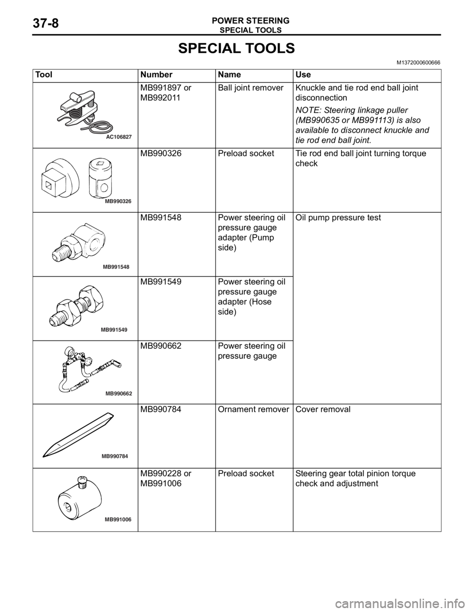
SPECIAL TOOLS
POWER STEERING37-8
SPECIAL TOOLS
M1372000600666
ToolNumberNameUse
AC106827
MB991897 or
MB9920
1 1Ball j o in t remo verKnuckle and tie rod e nd ball joint
discon
nection
NOTE: St eering linkage pu lle r
(MB990 635 o r MB991 1 13) is also
ava
ilab
l e to disconn ect knuckle and
tie ro
d end ball joint.
MB990326
MB9903 26Prel oad socketTi e rod end b a ll join t turning torq ue
che
c k
MB991548
MB9915 48Powe r stee ring oil
pressure g
auge
adapte
r (Pump
sid
e )Oil pump pre ssu re test
MB991549
MB991549Powe r stee ring oil
pressure g
auge
adapte
r (Hose
sid
e )
MB990662
MB9906 62Powe r stee ring oil
pressure g
auge
MB990784
MB990784Ornament removerCover removal
MB991006
MB9902 28 or
MB9910
06Prel oad socketSt e e ring gear to t a l pinion torque
che
ck and ad justmen t
Page 239 of 800
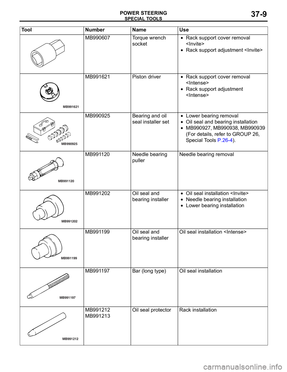
SPECIAL TOOLS
POWER STEERING37-9
MB990607Torque wrench
socket•Rack support cover removal
•Rack support adjustment
MB991621
MB991621Piston driver•Rack suppo rt co ver removal
•Rack support adjustment
MB990925
MB990925Bearing and o il
seal
inst alle r set•Lower bearing re moval
•Oil seal and bearing inst allatio n
•MB 9 9 0 9 2 7 , MB99 09 38, MB9 909 39
(For det
ails, refer to GROUP 26 ,
S
p e c ia l T o ols
P.26-4).
MB991120
MB991120Needle bearing
pullerNeedle bearing remova l
MB991202
MB991202Oil seal an d
bearing in
st aller•Oil seal in st allation
•Need le bearin g inst alla tion
•Lower bearing inst allation
MB991199
AB
MB991199Oil seal an d
bearing in
st allerOil seal inst allatio n
MB991197
MB991197Bar (long type)Oil seal inst allatio n
MB991212
MB991212
MB991213
Oil seal pro t ecto rRack insta llat i on
Tool Num ber Na me Use
Page 240 of 800
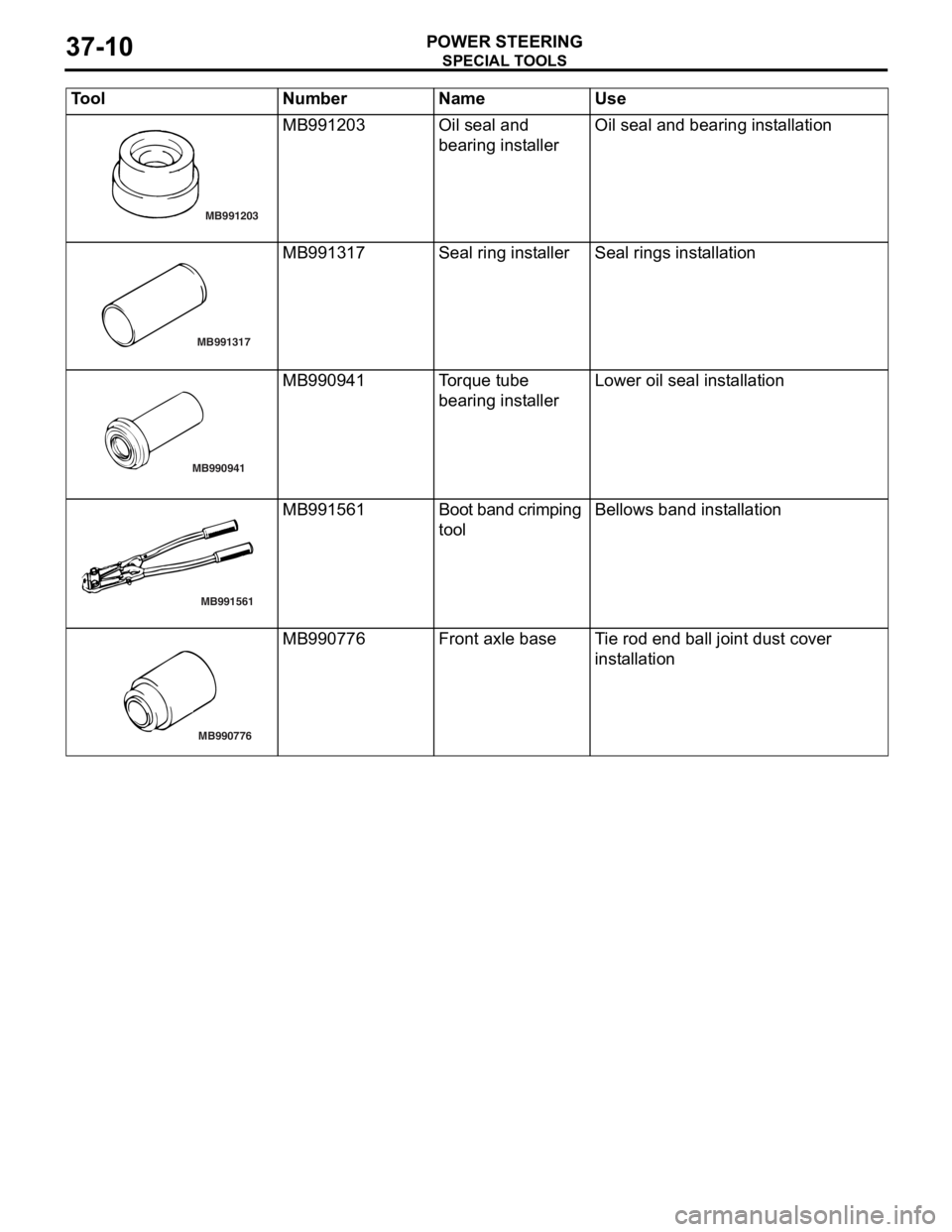
MB991203
SPECIA L T O OLS
POWER ST E E RING37-10
MB991203Oil seal an d
bearing in
st allerOil seal and bea ring inst allation
MB991317
MB991317Seal ring in st allerSeal rings inst a llat i on
MB990941
MB990941To rqu e tube
bearing in
st allerLower oil seal inst allation
MB991561
MB991561Boot ba nd crimp i n g
toolBellows ban d inst a lla tion
MB990776
MB990776Front ax le baseTi e rod end b a ll join t dust co ver
inst
a llat i on
Tool Num ber Na me Use