MITSUBISHI LANCER IX 2006 Service Manual
Manufacturer: MITSUBISHI, Model Year: 2006, Model line: LANCER IX, Model: MITSUBISHI LANCER IX 2006Pages: 800, PDF Size: 45.03 MB
Page 191 of 800

Page 192 of 800
STRUT ASSEMBLY
FRONT SUSPENSION33-10
>>B<< STRUT NUT (SELF-LOCKING NUT)
INSTALLATION
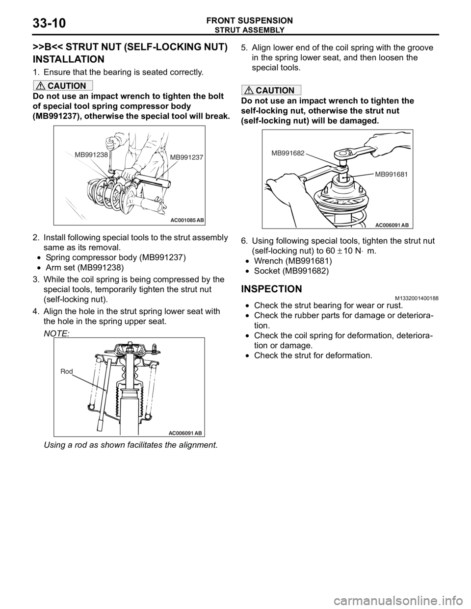
1. Ensure that the bearing is seated correctly.
CAUTION
Do not use an impact wrench to tighten the bolt
of special tool spring compressor body
(MB991237), otherwise the special tool will break.
AC001085 AB
MB991238MB991237
2. Install following special tools to the strut assembly
same as its removal.
•Spring compressor body (MB991237)
•Arm set (MB991238)
3. While the coil spring is being compressed by the
special tools, temporarily tighten the strut nut
(self-locking nut).
4. Align the hole in the strut spring lower seat with the hole in the spring upper seat.
NOTE:
AC006091 AB
Rod
Using a rod as shown fa cilitates the alignment.
5. Align lower end of the coil spring with the groove
in the spring lower seat, and then loosen the
special tools.
CAUTION
Do not use an impact wrench to tighten the
self-locking nut, otherwise the strut nut
(self-locking nut) will be damaged.
AC006091 AB
MB991681
MB991682
6. Using following special tools, tighten the strut nut
(self-locking nut) to 60
± 10 N⋅m.
•Wrench (MB991681)
•Socket (MB991682)
INSPECTIONM1332001400188
•Check the strut bearing for wear or rust.
•Check the rubber parts for damage or deteriora-
tion.
•Check the coil spring for deformation, deteriora-
tion or damage.
•Check the strut for deformation.
Page 193 of 800
LOWER ARM
FRONT SUSPENSION33-11
LOWER ARM
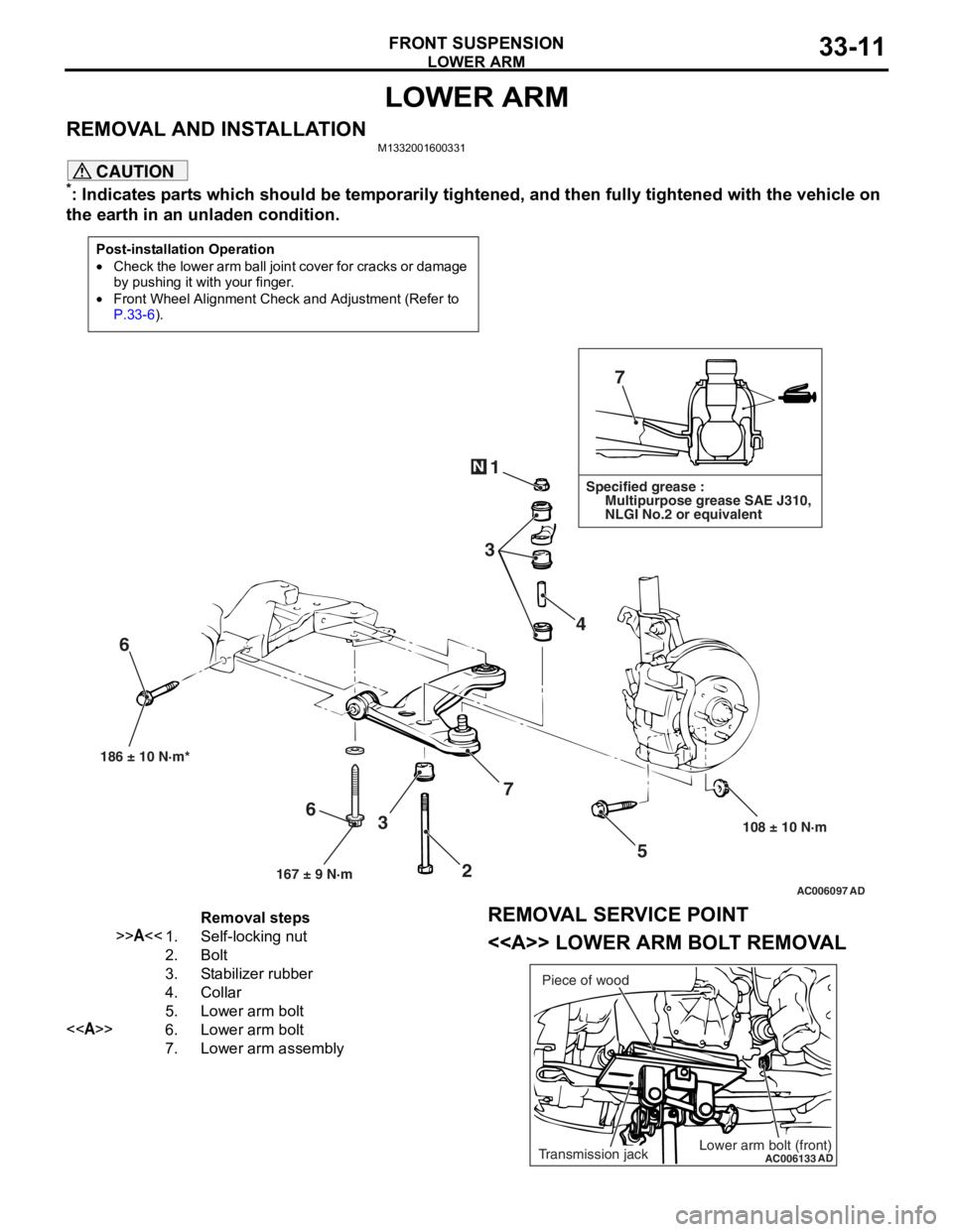
REMOVAL AND INSTALLATIONM1332001600331
CAUTION
*: Indicates parts which should be temporarily tightened, and then fully tightened with the vehicle on
the earth in an unladen condition.
Post-installation Operation
•Check the lower arm ball join t cover for cracks or damage
by pushing it with your finger.
•Front Wheel Alignment Check and Adjustment (Refer to
P.33-6).
AC006097 AD
7
1
3 4
5
108 ± 10 N·m
186 ± 10 N·m*
7
3
6
N
Specified grease :
Multipurpose grease SAE J310,
NLGI No.2 or equivalent
167 ± 9 N·m
6
2
Removal steps
>>A<<1.Self-locking nut
2.Bolt
3.Stabilizer rubber
4.Collar
5.Lower arm bolt
<>6.Lower arm bolt
7.Lower arm assembly
REMOVAL SERVICE POINT
<> LOWER ARM BOLT REMOVAL
AC006133
ADLower arm bolt (front)Transmission jackPiece of wood
Page 194 of 800
LOWER ARM
FRONT SUSPENSION33-12
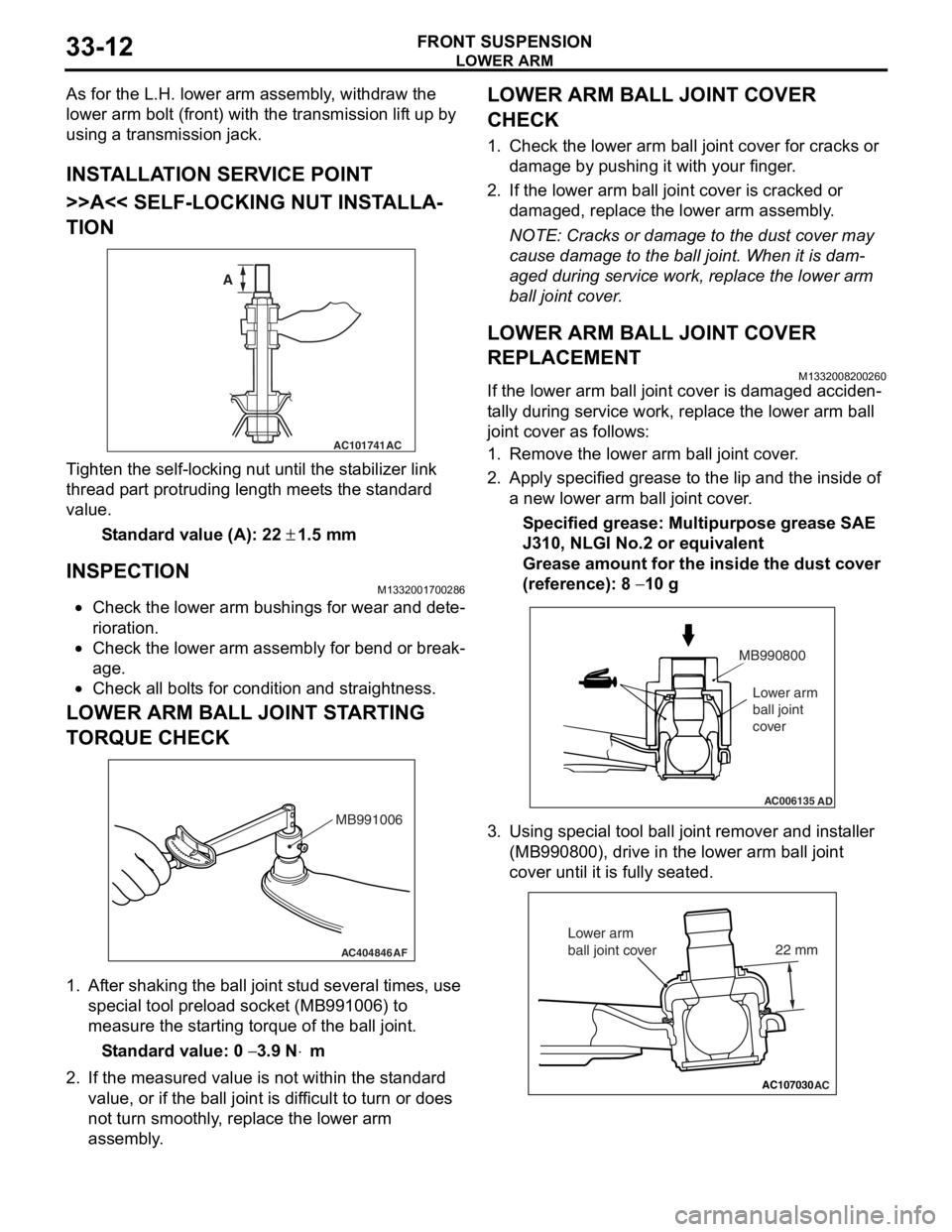
As for the L.H. lower arm assembly, withdraw the
lower arm bolt (front) with the transmission lift up by
using a transmission jack.
INSTALLATION SERVICE POINT
>>A<< SELF-LOCKING NUT INSTALLA-
TION
AC101741AC
A
T i ghten the self-locking nut un til t he st abilizer link
thread p
a rt protrud i ng length meet s the st a ndard
valu
e.
St andard va lue (A): 22 ± 1.5 m m
INSPECTION
M1332 0017 0028 6
•Check the lower arm bushing s for wear and det e-
riora t i o n.
•Check th e lo we r arm assemb ly for be nd or break-
age.
•Check all bo lt s for c ond ition and straightness.
LOWER ARM BALL JOINT ST ARTING
T
O RQUE CHECK
AC404846AF
MB991006
1.Af ter shaking the b a ll joint stud several times, use
special tool p r eloa d socke t (MB991 006) to
measure the st artin g torqu e of the ball joint.
St andard va lue: 0 − 3.9 N⋅m
2.If the measu r ed value is n o t within the st anda rd
value , or if the ba ll joint is dif f icu l t to t u rn or d oes
no t turn smo o thly , replace the lower a r m
asse mbly .
LOWER ARM BALL JOINT COVER
CHECK
1.Check t he lo we r arm b a ll joint co ver fo r cracks or
d a mag e by push i ng it with your finger .
2.If the lower arm ball joint co ver is cracked or
d a mag ed, rep l ace the lower arm assemb ly .
NOTE: Cracks or dama ge to t he dust co ver may
cause damage to the b a ll join t. When it is dam
-
aged du ring service wo rk, rep l ace the lower arm
b
a ll j o in t cover .
LOWER ARM BALL JOINT COVER
REPLACEMENT
M13320082 0026 0
If the lower arm ball jo int cove r is dama ged acciden-
ta lly durin g ser v ice work, repla c e th e lower arm b a ll
join
t cover as follows:
1.Remove the lower arm ball joint cover .
2.App l y specified grea se to the lip an d the inside of
a new lower arm ba ll join t cover .
Specified grease: Multipurpos e grease SAE
J310,
NLGI No.2 o r e quivale n t
Grease amount for the insi de the du st cove r
(re
f erence): 8
− 10 g
AC006135AD
MB990800
Lower arm
ball joint
cover
3. Using special tool ball joint remover and inst aller
(MB99080 0), drive in the lower arm ball jo int
cove r until it is fu lly se ated.
AC107030AC
22 mm
Lower arm
ball joint cover
Page 195 of 800
LOWER ARM
FRONT SUSPENSION33-13
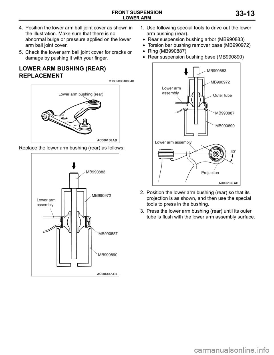
4. Position the lower arm ball joint cover as shown in the illustration. Make sure that there is no
abnormal bulge or pressure applied on the lower
arm ball joint cover.
5. Check the lower arm ball joint cover for cracks or damage by pushing it with your finger.
LOWER ARM BUSHING (REAR)
REPLACEMENT
M1332008100348
AC006136 AD
Lower arm bushing (rear)
Repl ace the lower arm bushing (rear) a s follows:
AC006137
AC
MB990883
MB990972
MB990887
MB990890
Lower arm
assembly
1.
Use following special tool s to drive out t he lo we r
a r m bushin g (rear).
•Rear suspension bu shing arb o r (MB99 0883)
•To rsion bar b u sh ing re mover base (MB9 90972 )
•Ring (MB990 887)
•
AC006138
AC
MB990883
MB990972
MB990887MB990890
Lower arm
assembly
Projection30˚
Lower arm assembly Outer tube
Rear susp
ension bu shing base (MB99089 0)
2.Position the lower ar m bushin g (rear) so tha t it s
p r ojection is as shown, an d then use the special
to ols to press in the bush i ng.
3.Press th e lower arm b u shing (rea r) until it s outer
tu be is flush with the lower a r m asse mbly surface.
Page 196 of 800
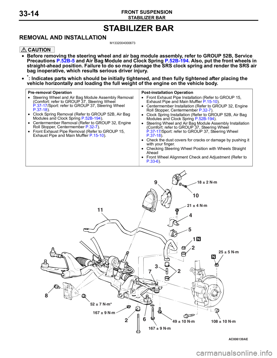
STABILIZER BAR
FRONT SUSPENSION33-14
STABILIZER BAR
REMOVAL AND INSTALLATIONM1332004000673
CAUTION
•Before removing the steering wheel and air bag module assembly, refer to GROUP 52B, Service
Precautions
P.52B-5 and Air Bag Module and Clock Spring P.52B-194. Also, put the front wheels in
straight-ahead position. Failure to do so may damage the SRS clock spring and render the SRS air
bag inoperative, which results serious driver injury.
•
Pre-removal Operation
•Steering Wheel and Air Bag Module Assembly Removal
(Comfort: refer to GROUP 37, Steering Wheel
P.37-17/Sport: refer to GROUP 37, Steering Wheel P.37-18).•Clock Spring Removal (Refer to GROUP 52B, Air Bag
Modules and Clock Spring P.52B-194).
•Centermember Removal (Ref er to GROUP 32, Engine
Roll Stopper, Centermember P.32-7).
•Front Exhaust Pipe Remova l (Refer to GROUP 15,
Exhaust Pipe and Main Muffler P.15-10).
Post-installation Operation
•Front Exhaust Pipe Installation (Refer to GROUP 15,
Exhaust Pipe and Main Muffler P.15-10).•Centermember Installation (Refer to GROUP 32, Engine
Roll Stopper, Centermember P.32-7).
•Clock Spring Installation (Refer to GROUP 52B, Air Bag
Modules and Clock Spring P.52B-194).
•Steering Wheel and Air Bag Module Assembly Installation
(Comfort: refer to GROUP 37, Steering Wheel
P.37-17/Sport: refer to GROUP 37, Steering Wheel P.37-18).•Check the dust covers for cracks or damage by pushing it
with your finger.
•Checking Steering Wheel Position with Wheels Straight
Ahead
•Front Wheel Alignment Check and Adjustment (Refer to P.33-6).
AC006139 AE
49 ± 10 N·m 108 ± 10 N·m
167 ± 9 N·m
167 ± 9 N·m
52 ± 7 N·m* 25 ± 5 N·m
21 ± 4 N·m
18 ± 2 N·m
10
9
4
5 1
2
2
3
7
6
2
11
8
*: Indicates parts which should be initially tightened, and then fully tightened after placing the
vehicle horizontally and loading the full weight of the engine on the vehicle body.
Page 197 of 800
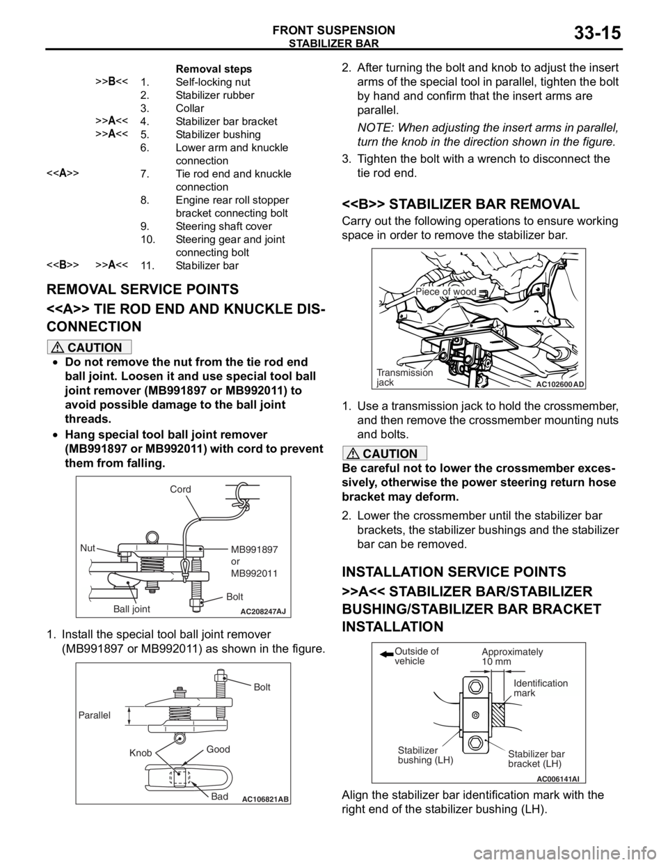
Removal steps
>>B<<1.Self-locking nut
2.Stabilizer rubber
3.Collar
>>A<<4.Stabilizer bar bracket
>>A<<5.Stabilizer bushing
6.Lower arm and knuckle
connection
<>7.Tie rod end and knuckle
connection
8.Engine rear roll stopper
bracket connecting bolt
9.Steering shaft cover
10.Steering gear and joint
connecting bolt
<>>>A<<11 .Stabilizer bar
STABILIZER BA R
FRONT SU SPENSION33-15
REMOVA L SER V ICE POINTS
<> TIE ROD END AND KNUCKLE DIS-
CONNECTION
CAUTION
•Do not remove the nut from the tie rod end
ball joint. Loosen it and use special tool ball
joint remover (MB991897 or MB992011) to
avoid possible damage to the ball joint
threads.
•
AC208247AJ
Cord
BoltMB991897
or
MB992011
Nut
Ball joint
Hang special tool ball joint remover
(MB991897 or MB992011) with cord to prevent
them from falling.
1. Install the special tool ball joint remover (MB991897 or MB992011) as shown in the figure.
AC106821
Knob
Parallel
Bolt
Good Bad
AB
2. After turning the bolt and knob to adjust the insert arms of the special tool in parallel, tighten the bolt
by hand and confirm that the insert arms are
parallel.
NOTE: When adjusting the insert arms in parallel,
turn the knob in the direction shown in the figure.
3. Tighten the bolt with a wrench to disconnect the tie rod end.
<> STABILIZER BAR REMOVAL
Carry out the following operations to ensure working
space in order to remove the stabilizer bar.
AC102600 AD
Piece of wood
Transmission
jack
1. Use a transmission jack to hold the crossmember,
and then remove the crossmember mounting nuts
and bolts.
CAUTION
Be careful not to lower the crossmember exces-
sively, otherwise the power steering return hose
bracket may deform.
2. Lower the crossmember until the stabilizer bar
brackets, the stabilizer bush ings and the stabilizer
bar can be removed.
INSTALLATION SERVICE POINTS
>>A<< STABILIZER BAR/STABILIZER
BUSHING/STABILIZ ER BAR BRACKET
INSTALLATION
AC006141 AI
Stabilizer bar
bracket (LH)
Outside of
vehicle
Stabilizer
bushing (LH) Approximately
10 mm
Identification
mark
Align the stabilizer bar iden
tification mark with the
right end of the stabilizer bushing (LH).
Page 198 of 800
STABILIZER BAR
FRONT SUSPENSION33-16
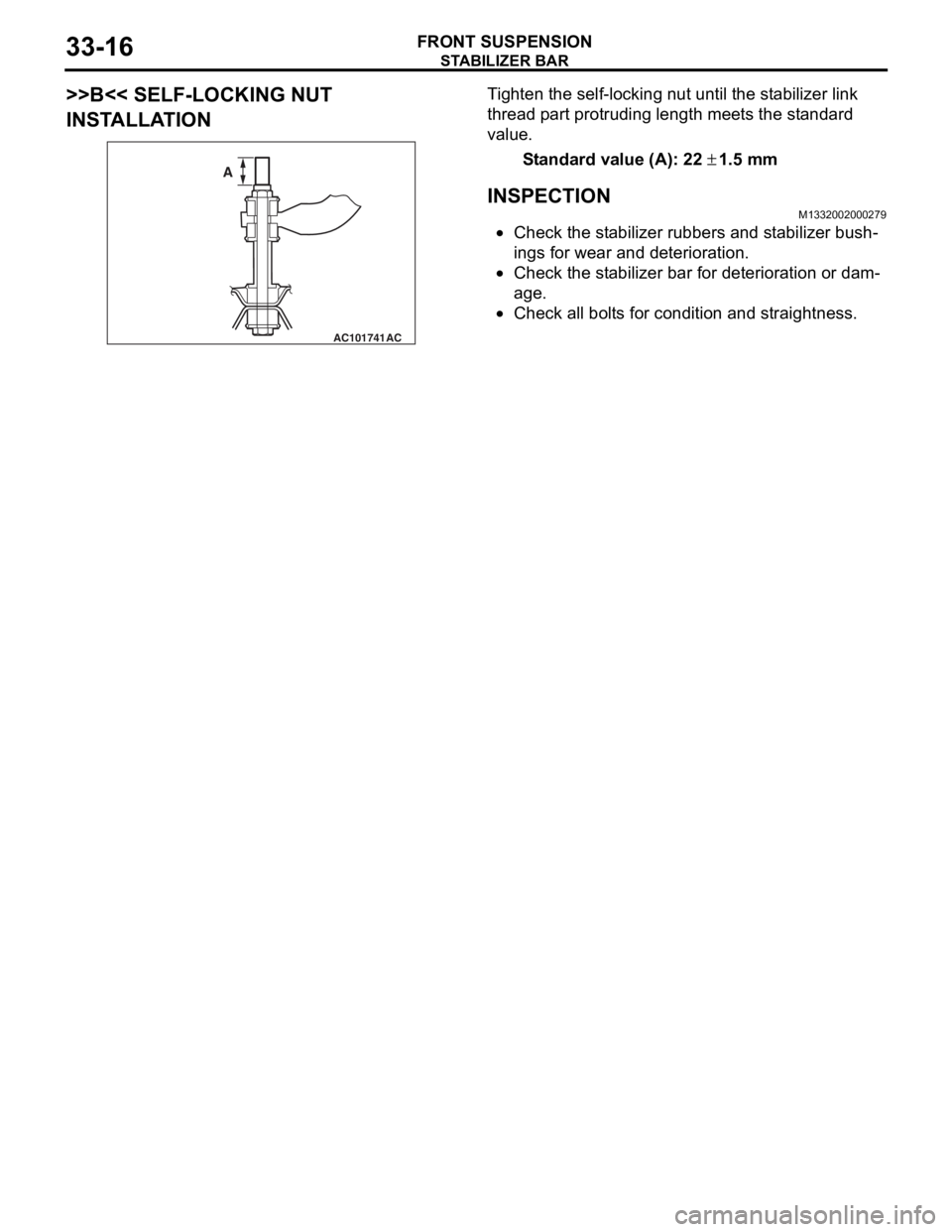
>>B<< SELF-LOCKING NUT
INSTALLATION
AC101741AC
A
Ti ghten the self-locking nut un til t he st ab ilizer link
thread
p a rt protrud i ng length mee t s the st a ndard
value.
St andard va lue (A): 22 ± 1.5 m m
INSPECTION
M1332 0020 0027 9
•Check the st abilizer rubb ers a nd st ab ilizer b u sh-
ings fo r wear and deterioration.
•Check the st abilizer bar for dete r iorat i on o r dam-
age.
•Check all bo lt s for cond itio n and straightness.
Page 199 of 800
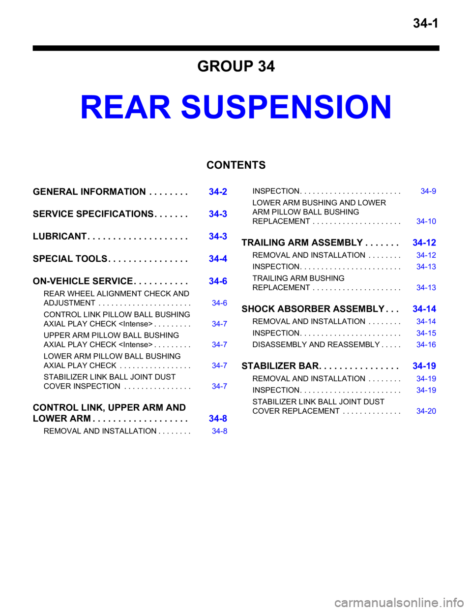
34-1
GROUP 34
REAR SUSPENSION
CONTENTS
GENERAL INFORMATION . . . . . . . .34-2
SERVICE SPECIFICATIONS . . . . . . .34-3
LUBRICANT . . . . . . . . . . . . . . . . . . . .34-3
SPECIAL TOOLS . . . . . . . . . . . . . . . .34-4
ON-VEHICLE SERVICE . . . . . . . . . . .34-6
REAR WHEEL ALIGNMENT CHECK AND
ADJUSTMENT . . . . . . . . . . . . . . . . . . . . . . 34-6
CONTROL LINK PILLOW BALL BUSHING
AXIAL PLAY CHECK
UPPER ARM PILLOW BALL BUSHING
AXIAL PLAY CHECK
LOWER ARM PILLOW BALL BUSHING
AXIAL PLAY CHECK . . . . . . . . . . . . . . . . . 34-7
STABILIZER LINK BALL JOINT DUST
COVER INSPECTION . . . . . . . . . . . . . . . . 34-7
CONTROL LINK, UPPER ARM AND
LOWER ARM . . . . . . . . . . . . . . . . . . .34-8
REMOVAL AND INSTALLATION . . . . . . . . 34-8
INSPECTION. . . . . . . . . . . . . . . . . . . . . . . . 34-9
LOWER ARM BUSHING AND LOWER
ARM PILLOW BALL BUSHING
REPLACEMENT . . . . . . . . . . . . . . . . . . . . . 34-10
TRAILING ARM ASSEMBLY . . . . . . .34-12
REMOVAL AND INSTALLATION . . . . . . . . 34-12
INSPECTION. . . . . . . . . . . . . . . . . . . . . . . . 34-13
TRAILING ARM BUSHING
REPLACEMENT . . . . . . . . . . . . . . . . . . . . . 34-13
SHOCK ABSORBER ASSEMBLY . . .34-14
REMOVAL AND INSTALLATION . . . . . . . . 34-14
INSPECTION. . . . . . . . . . . . . . . . . . . . . . . . 34-15
DISASSEMBLY AND REASSEMBLY . . . . . 34-16
STABILIZER BAR. . . . . . . . . . . . . . . .34-19
REMOVAL AND INSTALLATION . . . . . . . . 34-19
INSPECTION. . . . . . . . . . . . . . . . . . . . . . . . 34-19
STABILIZER LINK BALL JOINT DUST
COVER REPLACEMENT . . . . . . . . . . . . . . 34-20
Page 200 of 800
GENERAL INFORMATION
REAR SUSPENSION34-2
GENERAL INFORMATION
M1341000100717
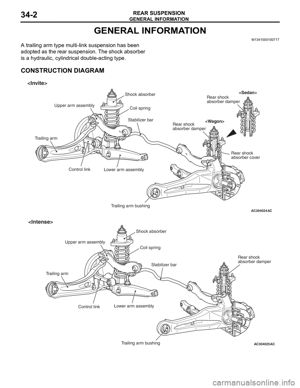
A trailing arm type multi-link suspension has been
adopted as the rear suspension. The shock absorber
is a hydraulic, cylindrical double-acting type.
CONSTRUCTION DIAGRAM
AC304024AC
Shock absorberCoil spring
Trailing arm bushing
Lower arm assembly
Control link
Trailing arm Upper arm assembly
Stabilizer barRear shock
absorber damper
Rear shock
absorber damper Rear shock
absorber cover
AC304025AC
Shock absorber
Trailing arm bushing
Control link
Trailing arm
Stabilizer bar
Coil spring
Lower arm assembly
Rear shock
absorber damper
Upper arm assembly