sensor MITSUBISHI LANCER IX 2006 Owner's Guide
[x] Cancel search | Manufacturer: MITSUBISHI, Model Year: 2006, Model line: LANCER IX, Model: MITSUBISHI LANCER IX 2006Pages: 800, PDF Size: 45.03 MB
Page 125 of 800
EMISSION CONTROL
ENGINE AND EMISSION CONTROL17-19
CATALYTIC CONVERTER
REMOVAL AND INSTALLATION <4G1,
4G6-M/T>
M1173003900773
Refer to GROUP 15 - Exhaust Pipe and Main Muffler P.15-10.
REMOVAL AND INSTALLATION
<4G6-A/T>
M1173003900784
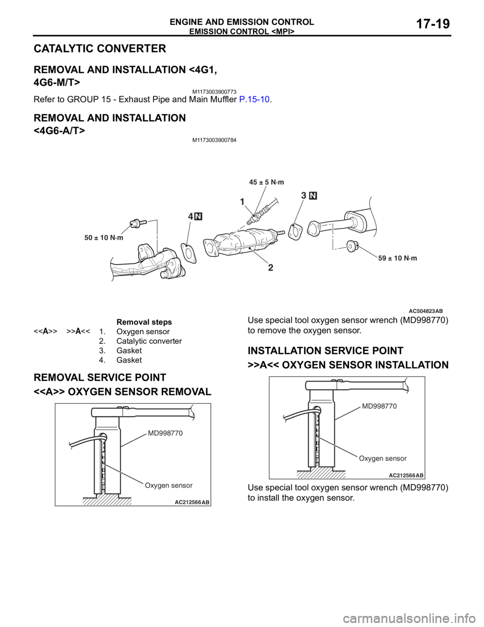
AC504823
2
3N
N4
59 ± 10 N·m
50 ± 10 N·m
1
45 ± 5 N·m
AB
Removal steps
<>>>A<<1.Oxygen sensor
2.Catalytic converter
3.Gasket
4.Gasket
REMOVA L SER V ICE POINT
<> OXYGEN SENSOR REMOV A L
AC212566AB
MD998770
Oxygen sensor
Use spec ia l tool oxyg en sen s or wrench (MD9987 70)
to remove
the oxyge n sen s or .
INSTALLA T ION SER VICE POINT
>>A<< OXYGEN SENSOR INST ALL A TION
AC212566AB
MD998770
Oxygen sensor
Use spec ia l tool oxyg en sen s or wrench (MD9987 70)
to inst
all the oxyge n sen s or .
Page 140 of 800
FRONT AXLE HUB ASSEMBLY
FRONT AXLE26-8
FRONT AXLE HUB ASSEMBLY
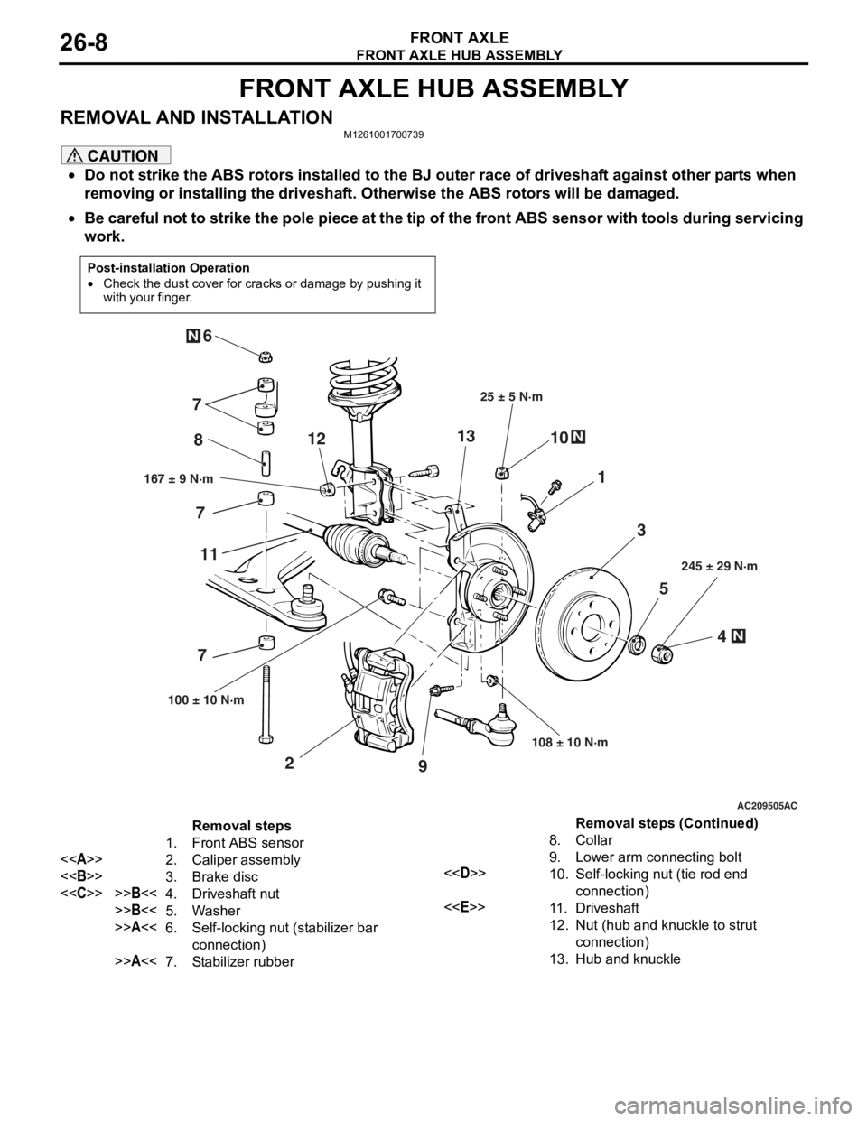
REMOVAL AND INSTALLATIONM1261001700739
CAUTION
•Do not strike the ABS rotors installed to the BJ outer race of driveshaft against other parts when
removing or installing the driveshaft. Otherwise the ABS rotors will be damaged.
•
Post-installation Operation
•Check the dust cover for cracks or damage by pushing it
with your finger.
AC209505
N
N
N
5
4
3
1
8
10
9
2
7
6
167 ± 9 N·m 25 ± 5 N·m
108 ± 10 N·m 245 ± 29 N·m
100 ± 10 N·m
AC
7 7
11 12
13
Removal steps
1. Front ABS sensor
<> 2. Caliper assembly
<> 3. Brake disc
<
>>B<<5. Washer
>>A<<6.Self-locking nut (stabilizer bar
connection)
>>A<<7.Stabilizer rubber
8.Collar
9. Lower arm connecting bolt
<
connection)
<
12.Nut (hub and knuckle to strut
connection)
13.Hub and knuckle
Be careful not to strike the pole piece at the tip of the front ABS sensor with tools during servicing
work.
Removal steps (Continued)
Page 146 of 800
DRIVESHAFT ASSEMBLY
FRONT AXLE26-14
DRIVESHAFT ASSEMBLY
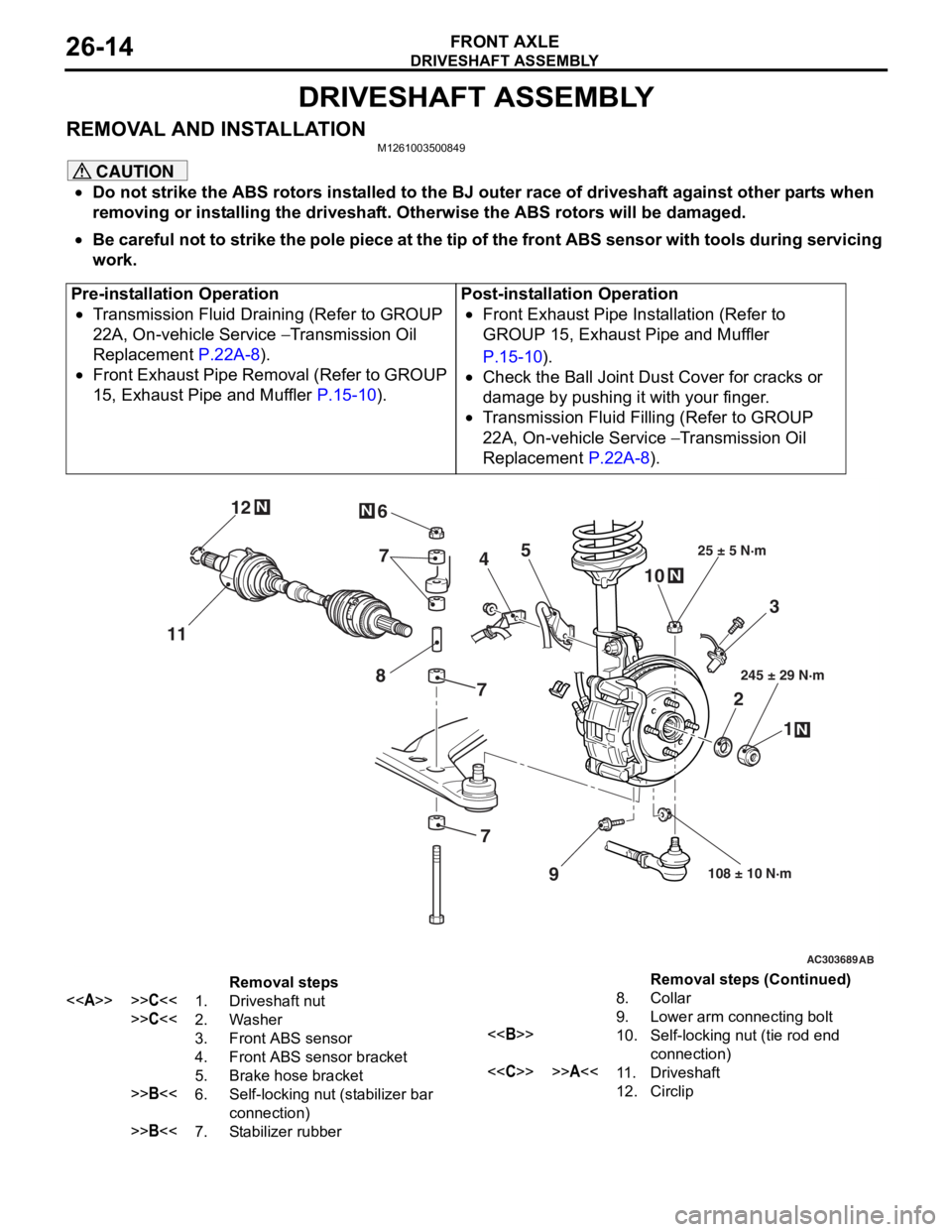
REMOVAL AND INSTALLATIONM1261003500849
CAUTION
•Do not strike the ABS rotors installed to the BJ outer race of driveshaft against other parts when
removing or installing the driveshaft. Otherwise the ABS rotors will be damaged.
•
Pre-installation Operation
•Transmission Fluid Draining (Refer to GROUP
22A, On-vehicle Service
− Transmission Oil
Replacement
P.22A-8).
•Front Exhaust Pipe Removal (Refer to GROUP
15, Exhaust Pipe and Muffler
P.15-10).
Post-installation Operation
•Front Exhaust Pipe Installation (Refer to
GROUP 15, Exhaust Pipe and Muffler
P.15-10).
•Check the Ball Joint Dust Cover for cracks or
damage by pushing it with your finger.
•Transmission Fluid Filling (Refer to GROUP
22A, On-vehicle Service
− Transmission Oil
Replacement
P.22A-8).
AC303689AB
9
N
N
NN
10
7
4
3
2 1
25 ± 5 N·m
245 ± 29 N·m
108 ± 10 N·m
8
5
6
11 12
77
Removal steps
<>>>C<<1.Driveshaft nut
>>C<<2.Washer
3.Front ABS sensor
4.Front ABS sensor bracket
5.Brake hose bracket
>>B<<6.Self-locking nut (stabilizer bar
connection)
>>B<<7.Stabilizer rubber
8.Collar
9.Lower arm connecting bolt
<>10.Self-locking nut (tie rod end
connection)
<
12.Circlip
Be careful not to strike the pole piece at the tip of the front ABS sensor with tools during servicing
work.
Removal steps (Continued)
Page 183 of 800
33-1
GROUP 33
FRONT
SUSPENSION
CONTENTS
GENERAL INFORMATIO N . . . . . . . .33-2
SERVICE SPECIFICATIONS . . . . . . .33-3
LUBRICANT . . . . . . . . . . . . . . . . . . . .33-3
SPECIAL TOOLS . . . . . . . . . . . . . . . .33-4
ON-VEHICLE SERVICE . . . . . . . . . . .33-6
FRONT WHEEL ALIGNMENT CHECK AND
ADJUSTMENT . . . . . . . . . . . . . . . . . . . . . . 33-6
LOWER ARM BALL JOINT AXIAL PLAY
CHECK . . . . . . . . . . . . . . . . . . . . . . . . . . . . 33-7
LOWER ARM BALL JOINT COVER
CHECK . . . . . . . . . . . . . . . . . . . . . . . . . . . . 33-7
STRUT ASSEMBLY . . . . . . . . . . . . . .33-7
REMOVAL AND INSTALLATION . . . . . . . . 33-7
INSPECTION. . . . . . . . . . . . . . . . . . . . . . . . 33-7
DISASSEMBLY AND REASSEMBLY . . . . . 33-8
INSPECTION. . . . . . . . . . . . . . . . . . . . . . . . 33-10
LOWER ARM . . . . . . . . . . . . . . . . . . .33-11
REMOVAL AND INSTALLATION . . . . . . . . 33-11
INSPECTION. . . . . . . . . . . . . . . . . . . . . . . . 33-12
LOWER ARM BALL JOINT COVER
REPLACEMENT . . . . . . . . . . . . . . . . . . . . . 33-12
LOWER ARM BUSHING (REAR)
REPLACEMENT . . . . . . . . . . . . . . . . . . . . . 33-13
STABILIZER BAR. . . . . . . . . . . . . . . .33-14
REMOVAL AND INSTALLATION . . . . . . . . 33-14
INSPECTION. . . . . . . . . . . . . . . . . . . . . . . . 33-16
WARNINGS REGARDING SERVICING OF SUPPLEMENTAL RESTRAINT SYSTEM (SRS) EQUIPPED VEHICLES
WARNING
•Improper service or maintenance of any component of the SRS, or any SRS-related component, can lead to
personal injury or death to service personnel (from inad vertent firing of the air bag) or to the driver and
paassenger (from rendering the SRS inoperative).
•Service or maintenance of any SRS component or SRS-related component must be performed only at an
authorized MITSUBISHI dealer.
•MITSUBISHI dealer personnel must thoroughly review this manual, and especially its GROUP 52B - Supplemental
Restraint System (SRS) before beginning any service or maintenance of any component of the SRS or any
SRS-related component.
NOTE
The SRS includes the following components: SRS air bag control unit, SRS warning light, front impact sensors, air bag module,
clock spring, and interconnecting wiring. Other SRS-related components (that may have to be removed/installed in connection
with SRS service or maintenance) are indicated in the table of contents by an asterisk (*).
Page 189 of 800
STRUT ASSEMBLY
FRONT SUSPENSION33-7
LOWER ARM BALL JOINT AXIAL PLAY
CHECK
M1332011300074
1. Raise the vehicle.
2. Remove the stabilizer link from the lower arm.
3. Move the lower arm up and down with your hands to check for an excessive play in the axial
direction of the ball joint. If there is an excessive
play, replace the lower arm assembly.
LOWER ARM BALL JOINT COVER
CHECK
M1332008600321
1. Press the lower arm ball joint cover with your finger to check that there are no cracks or
damage in the lower arm ball joint cover.
2. If the lower arm ball joint cover is cracked or damaged, replace the lower arm assembly.
NOTE: If the lower arm ball joint cover is cracked
or damaged, it is possible that there may also be
damage to the ball joint.
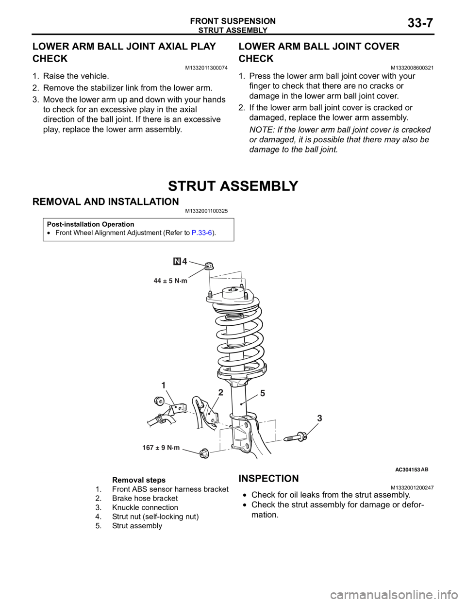
STRUT ASSEMBLY
REMOVAL AND INSTALLATION
M1332001100325
Post-installation Operation
•Front Wheel Alignment Adjustment (Refer to P.33-6).
AC304153
44 ± 5 N·m
1 2
3
4
N
AB
167 ± 9 N·m
5
Removal steps
1.Front ABS sensor
harness bracket
2.Brake hose bracket
3.Knuckle connection
4.Strut nut (self-locking nut)
5.Strut assembly
INSPECTION
M13320012 0024 7
•Check for oil leaks fro m the stru t assemb ly .
•Check the stru t assemb ly for damage o r defor-
mation.
Page 210 of 800
TRAILING ARM ASSEMBLY
REAR SUSPENSION34-12
TRAILING ARM ASSEMBLY
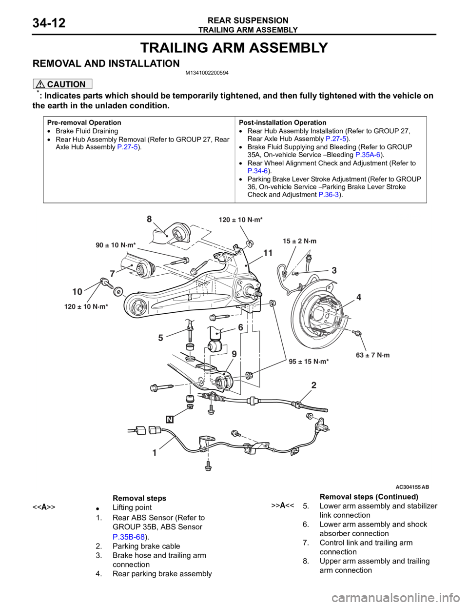
REMOVAL AND INSTALLATIONM1341002200594
CAUTION
*: Indicates parts which should be temporarily tightened, and then fully tightened with the vehicle on
the earth in the unladen condition.
Pre-removal Operation
•Brake Fluid Draining
•Rear Hub Assembly Removal (Refer to GROUP 27, Rear
Axle Hub Assembly P.27-5).
Post-installation Operation
•Rear Hub Assembly Installation (Refer to GROUP 27,
Rear Axle Hub Assembly
P.27-5).
•Brake Fluid Supplying and Bleeding (Refer to GROUP
35A, On-vehicle Service
− Bleeding P.35A-6).
•Rear Wheel Alignment Check and Adjustment (Refer to
P.34-6).
•Parking Brake Lever Stroke Ad justment (Refer to GROUP
36, On-vehicle Service
− Parking Brake Lever Stroke
Check and Adjustment
P.36-3).
AC101449
AC301223
AC304155 AB
90 ± 10 N·m*
120 ± 10 N·m* 95 ± 15 N·m*63 ± 7 N·m
6
7 8
1
10
11
23
4
120 ± 10 N·m*
15 ± 2 N·m
N
9
5
Removal steps
<>•Lifting point
1.Rear ABS Sensor (Refer to
GROUP 35B, ABS Sensor
P.35B-68).
2.Parking brake cable
3.Brake hose and trailing arm
connection
4.Rear parking brake assembly
>>A<<5.Lower arm assembly and stabilizer
link connection
6.Lower arm assembly and shock
absorber connection
7.Control link and trailing arm
connection
8.Upper arm assembly and trailing
arm connection
Removal steps (Continued)
Page 231 of 800
37-1
GROUP 37
POWER STEERING
CONTENTS
GENERAL INFORMATION . . . . . . . .37-3
SERVICE SPECIFICATIONS . . . . . . .37-6
LUBRICANTS . . . . . . . . . . . . . . . . . .37-7
SEALANTS . . . . . . . . . . . . . . . . . . . .37-7
SPECIAL TOOLS . . . . . . . . . . . . . . . .37-8
ON-VEHICLE SERVICE . . . . . . . . . . .37-11
STEERING WHEEL FREE PLAY CHECK . 37-11
STEERING ANGLE CHECK . . . . . . . . . . . . 37-11
TIE ROD END BALL JOINT TURNING
TORQUE CHECK . . . . . . . . . . . . . . . . . . . . 37-12
STATIONARY STEERING EFFORT
CHECK . . . . . . . . . . . . . . . . . . . . . . . . . . . . 37-12
STEERING WHEEL RETURN TO
CENTRE CHECK . . . . . . . . . . . . . . . . . . . . 37-13
DRIVE BELT TENSION CHECK. . . . . . . . . 37-13
FLUID LEVEL CHECK . . . . . . . . . . . . . . . . 37-13
FLUID REPLACEMENT . . . . . . . . . . . . . . . 37-13
POWER STEERING SYSTEM AIR
BLEEDING . . . . . . . . . . . . . . . . . . . . . . . . . 37-14
OIL PUMP PRESSURE TEST . . . . . . . . . . 37-14
POWER STEERING PRESSURE
SWITCH CHECK . . . . . . . . . . . . . . . . . . . . . 37-15
TIE ROD END BALL JOINT DUST
COVER CHECK . . . . . . . . . . . . . . . . . . . . . 37-15
STEERING COLUMN SHAFT ASSEMBLY
SHOCK ABSORBING MECHANISM
CHECK . . . . . . . . . . . . . . . . . . . . . . . . . . . . 37-15
STEERING WHEEL . . . . . . . . . . . . . .37-17
REMOVAL AND INSTALLATION
REMOVAL AND INSTALLATION
Continued on next page
WARNINGS REGARDING SERVICING OF SUPPLEMENTAL RESTRAINT SYSTEM (SRS) EQUIPPED VEHICLES
WARNING
•Improper service or maintenance of any component of the SRS, or any SRS-related component, can lead to
personal injury or death to service personnel (from inad vertent firing of the air bag) or to the driver and
paassenger (from renderin g the SRS inoperative).
•Service or maintenance of any SRS component or SRS-related component must be performed only at an
authorized MITSUBISHI dealer.
•MITSUBISHI dealer personnel must thoroughly review th is manual, and especially its GROUP 52B - Supplemental
Restraint System (SRS) before begi nning any service or maintenance of any component of the SRS or any
SRS-related component.
NOTE
The SRS includes the following components: SRS air bag control unit, SRS warning light, front impact sensors, air bag module,
clock spring, and interconnecting wiring. Other SRS-related components (that may have to be removed/installed in connection
with SRS service or maintenance) are indicated in the table of contents by an asterisk (*).
Page 391 of 800

70-1
GROUP 70
COMPONENT
LOC ATIONS
CONTENTS
ECU . . . . . . . . . . . . . . . . . . . . . . . . . .70-2
RELAY . . . . . . . . . . . . . . . . . . . . . . . .70-5
SENSOR. . . . . . . . . . . . . . . . . . . . . . .70-6
FUSIBLE LINK AND FU SE . . . . . . . .70-11
EARTH CABLE . . . . . . . . . . . . . . . . .70-12
SOLENOID VALVE . . . . . . . . . . . . . . .70-13
DIODE . . . . . . . . . . . . . . . . . . . . . . . . .70-14
EARTH . . . . . . . . . . . . . . . . . . . . . . . .70-15
INSPECTION CONNECTOR AND
SPARE CONNECTOR . . . . . . . . . . . .70-19
Page 396 of 800
SENSOR
COMPONENT LOCATIONS70-6
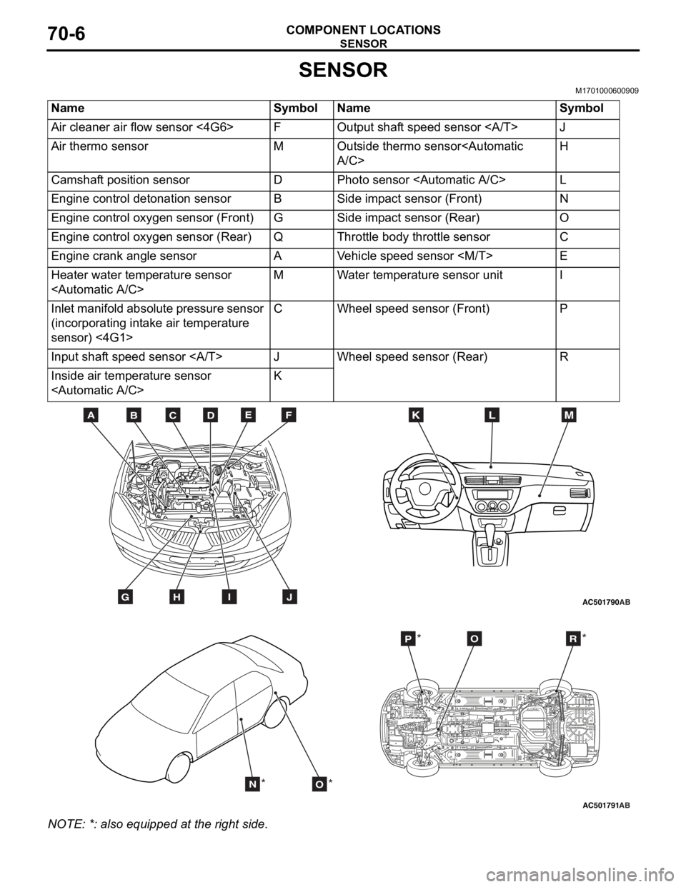
SENSOR
M1701000600909
NameSymbolNameSymbol
Air cleaner air flow sensor <4G6>FOutput shaft speed sensor J
Air thermo sensorMOutside thermo sensor
Camshaft position sensorDPhoto sensor
Engine control detonation sensorBSide impact sensor (Front)N
Engine control oxygen sensor (Front)GSide impact sensor (Rear)O
Engine control oxygen sensor (Rear)QThrottle body throttle sensorC
Engine crank angle sensorAVehicle speed sensor
Heater water temperature sensor
Inlet manifold absolute pressure sensor
(incorporating intake air temperature
sensor) <4G1>CWheel speed sensor (Front)P
Input shaft speed sensor JWheel speed sensor (Rear)R
Inside air temperature sensor
AC501790
BDCFEA
GHIJ
MKL
AB
AC501791AB
NO
POR
** *
*
NO
TE: *: also eq uipp ed at t he rig h t side.
Page 397 of 800
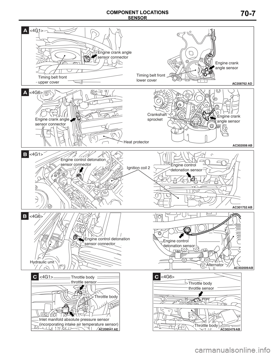
AC208762
A
AD
Timing belt front
upper coverTiming belt front
lower coverEngine crank
angle sensor
<4G1>
Engine crank angle
sensor connector
AC302008
A<4G6>
ABHeat protector
Crankshaft
sprocket
Engine crank angle
sensor connectorEngine crank
angle sensor
AC301752
B
AB
Ignition coil 2
<4G1>
Engine control detonation
sensor connector
Engine control
detonation sensor
AC302009
B
AB
Hydraulic unit
<4G6>
Alternator
Engine control detonation
sensor connectorEngine control
detonation sensor
AC208541
C
AE
<4G1>
Throttle body
Throttle body
throttle sensor
Inlet manifold absolute pressure sensor
(incorporating intake air temperature sensor)
AC302479
AB
C
Throttle body
<4G6>
Throttle body
throttle sensor
SENSOR
COMPONENT LOCA TIONS70-7