compressor MITSUBISHI MONTERO 2000 Service Repair Manual
[x] Cancel search | Manufacturer: MITSUBISHI, Model Year: 2000, Model line: MONTERO, Model: MITSUBISHI MONTERO 2000Pages: 1839, PDF Size: 29.19 MB
Page 90 of 1839

ENGINE <4D5> -Service Specifications/Sealants11B-3
SERVICE SPECIFICATIONS
ItemsStandard valueLimit
A/C compressor drive beltVibration frequency Hz157 - 176–
(When inspection)Tension N260 - 325–
Deflection mm
A/C compressor drive beltVibration frequency Hz157 - 176–
(When adjustment)Tension N260 - 325–
Deflection mm
A/C compressor drive beltVibration frequency Hz192 - 208–
(When replacement)Tension N390 - 450–
Deflection mm
Valve clearance (at hot) mm0.25-
Injection timing (Value indicated on dial gauge mm)9_ATDC (1±0.03)-
Idle speed r/min750±100-
Compression pressure kPa (at engine speed of 280 r/min)3,040Min. 2,256
Compression pressure difference of all cylinder (at engine speed of 280
r/min) kPa-Max. 294
Timing belt tension mm4-5
Timing belt B tension mm4-5
SEALANTS
ItemsSpecified sealantRemarks
Oil panMITSUBISHI GENUINE PART
MD970389 or equivalentSemi-drying sealant
Semi-circular packing and rocker
cover gasket seal, and cylinder head
seal3M ATD Part No. 8660 or equivalent
www.WorkshopManuals.co.uk
Purchased from www.WorkshopManuals.co.uk
Page 143 of 1839

ENGINE <4M4> -General Information/Service Specifications11C-2
GENERAL INFORMATION
Items4M41
Total displacement mL3,200
Bore´Stroke mm98.5´105.0
Compression ratio17.0
Camshaft arrangementDOHC
Number of valveIntake8
Exhaust8
Valve timingIntakeOpeningBTDC 13_
ClosingABDC 31_
ExhaustOpeningBBDC 55_
ClosingATDC 17_
Fuel systemDistribution type injection pump
Rocker armRoller type
SERVICE SPECIFICATIONS
ItemsStandard valueLimit
Alternator drive beltVibration frequency Hz122 - 161–
(When inspection)Tension N207 - 363–
Deflection mm
Alternator drive beltVibration frequency Hz122 - 136–
(When adjustment)Tension N207 - 259–
Deflection mm
Alternator drive beltVibration frequency Hz149 - 161–
(When replacement)Tension N311 - 363–
Deflection mm
A/C compressor drive beltVibration frequency HzA177 - 191–
(When inspection)B145 - 156–
Tension NC343 - 392–
Deflection mm
A/C compressor drive beltVibration frequency HzA177 - 191–
(When adjustment)B145 - 156–
Tension NC343 - 392–
Deflection mm
A/C compressor drive beltVibration frequency HzA177 - 191–
(When replacement)B145 - 156–
Tension NC490 - 539–
Deflection mm
www.WorkshopManuals.co.uk
Purchased from www.WorkshopManuals.co.uk
Page 190 of 1839

2
GENERAL INFORMATION
Items 4M41
Total displacement mℓ
3,200
Bore x Stroke mm 98.5 x 105.0
Compression ratio 17.0
Camshaft arrangement DOHC
Intake 8Number of valve
Exhaust 8
Opening BTDC 13ºIntake
Closing ABDC 31º
Opening BBDC 55º
Valve timing
Exhaust
Closing ATDC 17º
Fuel system Distribution type injection pump
Rocker arm Roller type
SERVICE SPECIFICATIONS
Items Standard value Limit
Vibration frequentcy Hz 122 – 161 -
Tension N 207 – 363 -
Alternator drive belt
(When inspection)
Deflection mm
Vibration frequentcy Hz 122 – 136 -
Tension N 207 – 259 -
Alternator drive belt
(When adjustment)
Deflection mm
Vibration frequentcy Hz 149 – 161 -
Tension N 311 – 363 -
Alternator drive belt
(When replacement)
Deflection mm
A 177 – 191 -Vibration frequentcy
Hz
B 145 – 156 -
Tension N C 343 – 392 -
A 169 – 189
A/C compressor drive belt
(When inspection)
Deflection mm
B 111 – 124
A 177 – 191 -A 285 – 355Vibration frequentcy
Hz
B 145 – 156 -A 7.0 – 8.0
Tension N C 343 – 392 -A 169 – 189
B 111 – 124
A/C compressor drive belt
(When adjustment)
Deflection mm
A 285 – 355
A 177 – 191 -A 7.0 – 8.0Vibration frequentcy
Hz
B 145 – 156 -A 207 – 223
Tension N C 490 – 539 -B 135 – 146
A 425 – 500
A/C compressor drive belt
(When replacement)
Deflection mm
A 6.0 – 6.5
11C-2ENGINE <4M4> - General Information/Service Specifications
www.WorkshopManuals.co.uk
Purchased from www.WorkshopManuals.co.uk
Page 218 of 1839

GDI -General Information13A-4
SELF-DIAGNOSIS FUNCTION
DWhen an abnormality is detected in one
of the sensors or actuators related to
emission control, the engine warning lamp
(check engine lamp) illuminates or flashes
as a warning to the driver.
DWhen an abnormality is detected in one
of the sensors or actuators, a diagnosis
code corresponding to the abnormality is
output.
DThe engine-ECU records the engine
operating condition when the diagnosis
code is set. This data is called “freezeframe” data.
This data can be read by using the MUT-II,
and can then be used in simulation tests
for troubleshooting.
DThe RAM data inside the engine-ECU
related to the sensors and actuators can
be read by means of the MUT-II. In addition,
the actuators can be force-driven under
certain circumstances.
OTHER CONTROL FUNCTIONS
1. Fuel Pump Control
Turns the fuel pump relay ON so that current
is supplied to the fuel pump while the engine
is cranking or running.
2. A/C Relay Control
Turns the compressor clutch of the A/C
ON and OFF.3. Purge Control Solenoid Valve Control
Refer to GROUP 17.
4. EGR Control Servo Control
Refer to GROUP 17.
GENERAL SPECIFICATIONS
ItemsSpecifications
Throttle bodyThrottle bore mm65
Throttle position sensorVariable resistor type
Throttle valve control servoBrushless DC-motor type
Engine-ECUIdentification model No.E2T79271
E2T79272
Engine-Identification model No.E2T76277
A/T-ECU
E2T76278
www.WorkshopManuals.co.uk
Purchased from www.WorkshopManuals.co.uk
Page 316 of 1839

GDI -Troubleshooting
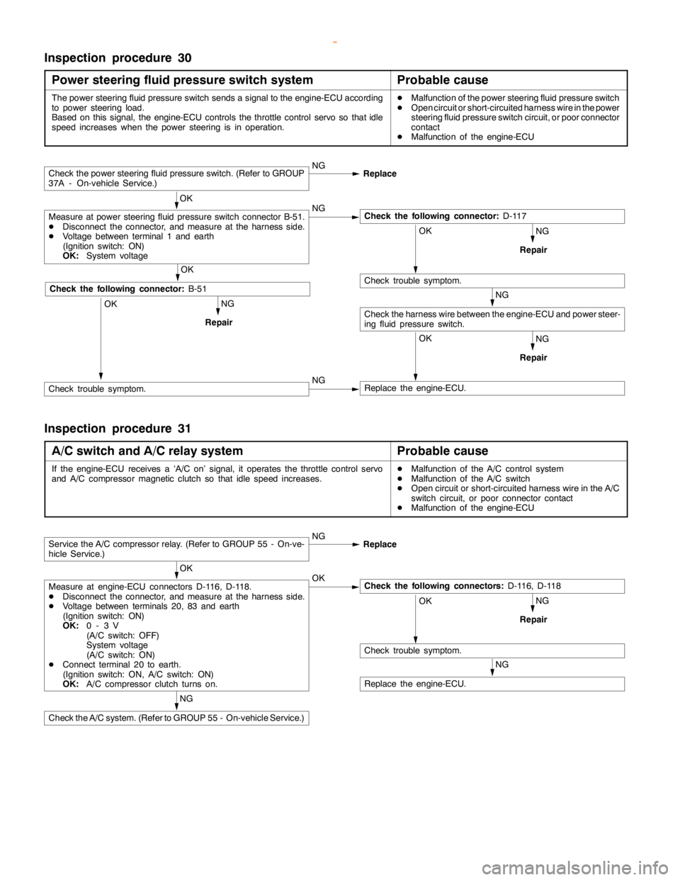
Inspection procedure 30
Power steering fluid pressure switch system
Probable cause
The power steering fluid pressure switch sends a signal to the engine-ECU according
to power steering load.
Based on this signal, the engine-ECU controls the throttle control servo so thatidle
speed increases when the power steering is in operation.DMalfunction of the power steering fluid pressure switch
DOpen circuit or short-circuited harness wire in the power
steering fluid pressure switch circuit, or poor connector
contact
DMalfunction of the engine-ECU
NG
NG
RepairOK
Replace the engine-ECU.
NG
Repair
Check the power steering fluid pressure switch. (Refer to GROUP
37A - On-vehicle Service.)NG
Replace
OK
Measure at power steering fluid pressure switch connector B-51.
DDisconnect the connector, and measure at the harness side.
DVoltage between terminal 1 and earth
(Ignition switch: ON)
OK:
System voltageNGCheck the following connector:
D-117
OK
Check trouble symptom.
Check the harness wire between the engine-ECU and power steer-
ing fluid pressure switch.NG
RepairOK
OK
Check the following connector:
B-51
Check trouble symptom.NG
Inspection procedure 31
A/C switch and A/C relay system
Probable cause
If the engine-ECU receives a ‘A/C on’ signal, it operates the throttle control servo
and A/C compressor magnetic clutch so thatidlespeed increases.DMalfunction of the A/C control system
DMalfunction of the A/C switch
DOpen circuit or short-circuited harness wire in the A/C
switch circuit, or poor connector contact
DMalfunction of the engine-ECU
NG
NG
RepairOK
Check trouble symptom.
NG
Replace the engine-ECU.
Service the A/C compressor relay. (Refer to GROUP 55 - On-ve-
hicle Service.)NG
Replace
OK
Measure at engine-ECU connectors D-116, D-118.
DDisconnect the connector, and measure at the harness side.
DVoltage between terminals 20, 83 and earth
(Ignition switch: ON)
OK:
0-3V
(A/C switch: OFF)
System voltage
(A/C switch: ON)
DConnect terminal 20 to earth.
(Ignition switch: ON, A/C switch: ON)
OK:
A/C compressor clutch turns on.OKCheck the following connectors:
D-116, D-118
Check the A/C system. (Refer to GROUP 55 - On-vehicle Service.)
www.WorkshopManuals.co.uk
Purchased from www.WorkshopManuals.co.uk
Page 321 of 1839

GDI -Troubleshooting
Item
No.Reference
page Inspection
procedure
No. Normal condition Requirements Check items
25BarometricIgnition switch: ONAltitude: 0 m101 kPaCode No.13A-19
pressure sen-
sor
Altitude: 600 m95 kPa
P0105
Altitude: 1,200 m88 kPa
Altitude: 1,800 m81 kPa
26Accelerator
pedal positionIgnition switch: ON
(Depress and re-Release the accel-
erator pedal.ONProcedure
No.2813A-100
switchlease the accelera-
tor pedal several
times)
Depress the accel-
erator pedal slight-
ly.OFF
27Power steer-
ing fluid pres-Engine: IdlingSteering wheel sta-
tionaryOFFProcedure
No.3013A-102
sure switch
Steering wheel
turningON
28A/C switchEngine: Idling (The
A/C compressor isA/C switch: OFFOFFProcedure
No.3113A-100
A/C compressor is
running when the
A/C switch is on.)
A/C switch: ONON
No.31
31Small lamp
switchEngine: IdlingLighting switch:
OFFOFFProcedure
No.3313A-104
Lighting switch: ONON
34Air flow sensorEngine: After hav-Engine is idlingONCode No.13A-17
reset signaling warmed up
3,000 r/minOFF
P0100
37Volumetric effi-
ciencyDEngine coolant
temperature:Engine is idling20 - 40%--
80 - 95_C
DLamps, electric
cooling fan and2,500 r/min10 - 30%
cooling fan and
all accessories:
OFF
DTransmission:
Neutral
Engine is suddenly
racedVolumetric effi-
ciency increases in
response to racing
38Crank angle
sensorDEngine: Cranking [reading is possible
at 2,000 r/min or less]
DTachometer: ConnectedEngine speeds dis-
played on the
MUT-IIand
tachometer are
identical.--
www.WorkshopManuals.co.uk
Purchased from www.WorkshopManuals.co.uk
Page 322 of 1839

GDI -Troubleshooting
Item
No.Reference
page Inspection
procedure
No. Normal condition Requirements Check items
41Injector drive
time *2DEngine coolant
temperature:
80 - 95_CIdling0.3 - 0.8 ms*1--
80 - 95_C
DLamps, electric
cooling fan and
all accessories:
2,500 r/min0.4 - 1.0 ms
all accessories:
OFF
DTransmission:
Neutral
Sudden racingIncreases
44Ignition
advanceDEngine: After
warm-upIdling5-20_BTDC *1Code No.
P030013A-53
advancewarm-up
DSet a timing
light.
2,500 r/min15 - 35_BTDC
P0300
49A/C relayEngine: After
warm-up, idlingA/C switch: OFFOFF (compressor
clutch is not oper-
ating)Procedure
No.3113A-102
A/C switch: ONON (compressor
clutch is operating)
59Oxygen sen-
sor (rear)DTransmission:
2nd gear
DDrive with
throttle widely
open3,500 r/min600 - 1,000 mVCode No.
P013613A-31
67Stop lamp
switchIgnition switch: ONBrake pedal: De-
pressedOFFProcedure
No.3213A-103
Brake pedal: Re-
leasedON
68EGR valveDEngine coolant
temperature:
80 - 95_C
DLamps, electricIdling2 - 20 STEPCode No.
P040313A-60
cooling fan and
all accessories:
OFF
DTransmission:
Neutral
2,500 r/min0 - 10 STEP
74Fuel pressure
sensorDEngine coolant
temperature:
80 - 95_C
DLamps, electric
cooling fan and
all accessories:
OFF
DTransmission:
NeutralEngine: Idling4 - 6.9 MPaCode No.
P019013A-36
www.WorkshopManuals.co.uk
Purchased from www.WorkshopManuals.co.uk
Page 326 of 1839

GDI -Troubleshooting
Terminal
No.Normal condition Check requirements (engine condition) Check item
16Purge control solenoid valveDEngine cool-Engine: stoppedSystem voltage
ant tempera-
ture:
80 - 95_C
DIgnition
switch: ON
Engine: Start the
engine, and then
increase engine
speed up to 3,500
r/min.Voltage decreases.
18Condenser fan relayCondenser fan is not operating.System voltage
Condenser fan is operating.0-3V
20Fuel pump relayIgnition switch:Engine: stoppedSystem voltage
ON
Engine: idling0-3V
21A/C relayDEngine: idlingSystem voltage, or changes
DA/C switch: OFF®ON
(Compressor is operating)from momentarily 6 V or
more to 0®3V
31Engine warning lampIgnition switch: OFF®ON0-3V®System voltage
(after several seconds)
41Sensor power supplyIgnition switch: ON4.5 - 5.5 V
42Power supply to accelerator
pedal position sensor (1st
channel)Ignition switch: ON4.5 - 5.5 V
43Crank angle sensorEngine: Cranking0.4 - 4.0 V
Engine: Idling1.5 - 2.5 V
44Engine coolant temperature
sensorIgnition switch:
ONEngine coolant
temperature: 0_C3.2 - 3.5 V
Engine coolant
temperature:
20_C2.3 - 2.9 V
Engine coolant
temperature:
40_C1.5 - 2.1 V
Engine coolant
temperature:
80_C0.4 - 1.0 V
45Engine ignition signalEngine: 3,000 r/min0.3 - 3.0 V
www.WorkshopManuals.co.uk
Purchased from www.WorkshopManuals.co.uk
Page 328 of 1839

GDI -Troubleshooting
Terminal
No.Normal condition Check requirements (engine condition) Check item
63Stop lamp switchDepress the brake pedal.System voltage
Release the brake pedal.0-3V
65A/C switch (2nd channel)Refer to GROUP 55 - Troubleshooting “Check at the A/C-ECU
terminal, engine-ECU output terminals.”
66Clutch switchDepress the clutch pedal.0-3V
Release the clutch pedal.System voltage
68Ignition switch-STEngine: Cranking8V or more
71Oxygen sensor (front)Engine: Warm up, and then hold the
engine speed at 2,500r/min (Use a
digital voltmeter).0«0.8 V alternates.
76Air flow sensor reset signalEngine: Idling0-1V
Engine: 3,000 r/min6-9V
78Throttle position sensor
(2nd channel)Ignition switch:
ONRelease the
accelerator pedal.4.5 - 5.5 V
Depress the
accelerator pedal
fully.0.4 - 0.6 V
79Accelerator pedal position
switchIgnition switch:
ONRelease the
accelerator pedal.0-1V
Depress the
accelerator pedal
fully.4V or more
80Vehicle speed sensorDIgnition switch: ON
DMove the vehicle forward.0«system voltage
alternates.
83A/C switch (1st channel)Engine: IdlingA/C switch: OFF0-3V
A/C switch: ON
(Compressor is
operating)System voltage
88Small lamp switchLighting switch: OFF0-3V
Lighting switch: ON (Taillamp: ON)System voltage
89Oxygen sensor heaterEngine: Idling0-3V
(front)
Engine: 3,500 r/minSystem voltage
90Oxygen sensor heaterEngine: Idling0-3V
(rear)
Engine: 3,500 r/minSystem voltage
92Fuel pressure sensorEngine: Idling0.3 - 4.7 V
www.WorkshopManuals.co.uk
Purchased from www.WorkshopManuals.co.uk
Page 408 of 1839
