MITSUBISHI MONTERO 2000 Service Repair Manual
MONTERO 2000
MITSUBISHI
MITSUBISHI
https://www.carmanualsonline.info/img/19/57331/w960_57331-0.png
MITSUBISHI MONTERO 2000 Service Repair Manual
Trending: audio, airbag off, parking, wheel, tow bar, interior, directional lamp
Page 1531 of 1839
Page 1532 of 1839

SRS -Air Bag Modules and Clock Spring52B-32
AIR BAG MODULES AND CLOCK SPRING
Caution
1. Disconnect the negative (–) battery terminal
and wait for 60 seconds or more before
starting work. Also, the disconnected
battery terminal should be insulated with
tape. (Refer to P.52B-4.)
2. Never attempt to disassemble or repair the
air bag modules and clock spring.
If faulty, just replace with new one(s).
3. Do not drop the air bag modules or clock
spring or allow contact with water, grease
or oil.
Replace if a dent, crack, deformation or rust
are present.
4. Store the air bag modules on a flat surface
with the deployment surface facing up.
Do not place anything on top of them.5. Do not store the air bag modules in a place
more than 93_
C.
6. When the driver’s and front passenger’s air
bags have been deployed, replace the
driver’s and passenger’s air bag modules
with new ones.
7. Put on gloves and safety glasses when
handling deployed air bags.
8. When discarding the undeployed air bag
module(s), be sure to deploy the air bag(s)
in advance as specified in the service
procedure.
(Refer to to P.52B-43.)
www.WorkshopManuals.co.uk
Purchased from www.WorkshopManuals.co.uk
Page 1533 of 1839
1
2
3
Sectio n B –B
S ectio n A –A
A
A
B B C
olu m nsw it c h
4
NO TE
: in dic a te s ta b. C
la w
C la w
S
ectio n C –C S
ectio n D –D
5
33 1
1
3
.9 ±
0.4 N×
m 3
.9 ±
0.4 N×
m
0
.6 9 ±
0.1 5 N×
m
5 0 ±
5 N×
m C
Page 1534 of 1839
1
2
R em oval ste p s
D Upper glo ve box (R efe r to GRO UP
5 2A -In str u m ent Panel. )
D Glo ve box (R efe r to GRO UP 52A -
I n str u m ent Panel. )
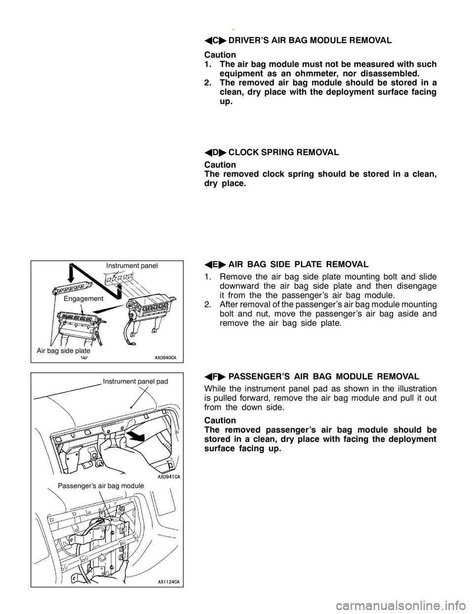
A E"
1. A ir bag sid e pla te
A F"
2. P asse nger’s air bag module I
n sta lla tio n ste p s
" AA
D
Pre -in sta lla tio n in sp ectio n
2 . P asse nger’s air bag module
1 . A ir bag sid e pla te
D Glo ve box (R efe r to GRO UP 52A -
I n str u m ent Panel. )
D Upper glo ve box (R efe r to GRO UP
5 2A -In str u m ent Panel. )
D Connect th e negativ e (- ) batte ry
t e rm in al.
" DA
D
Post- in sta lla tio n in sp ectio n
w
ww.W ork sh opM an uals .c o .u k
P urc h ased f r o m w ww.W ork sh opM an uals .c o .u k
Page 1535 of 1839

1
S id e air bag
m odule
R em oval ste p s
A G"
1. Fro nt se at back asse m bly I
n sta lla tio n ste p s
" AA
D
Pre -in sta lla tio n in sp ectio n
1 . Fro nt se at back asse m bly
D Connect th e negativ e (- ) batte ry
t e rm in al.
" DA
D
Post- in sta lla tio n in sp ectio n
R EM OVA L SER VIC E PO IN TS
A A"
CO VER REM OVA L
I n se rt th e sp ecia l to ol as sh ow n in th e illu str a tio n to re m ove
t h e co ve r.
N O TE
T he arro w in th e illu str a tio n sh ow s th e notc h fo r th e sp ecia l
t o ol.
A B"
STE ER IN G WHEEL AND AIR BAG MODULE
A SSEM BLY REM OVA L
1 . Rem ove th e air bag module and dis co nnect th e horn
s w it c h co nnecto r th ro ugh sp ace pro duce d afte r th e
r e m ova l of th e ste erin g wheel.
2 . Loose n th e bolt co m ple te ly and th en re m ove th e ste erin g
w heel asse m bly .
N O TE
U se a hexa gonalb it so cke to r a hexa gonalw re nch havin g
a n eff e ctiv e le ngth of 75 mm or m ore in th e hexa gonal
s e ctio n and th e dia m ete r of 8 mm or m ore .
Page 1536 of 1839
A
ir bag sid e pla te I
n str u m entp anel I
n str u m entp anelp ad P
asse nger’s air bag m odule
w
ww.W ork sh opM an uals .c o .u k
P urc h ased f r o m w ww.W ork sh opM an uals .c o .u k
Page 1537 of 1839
Page 1538 of 1839
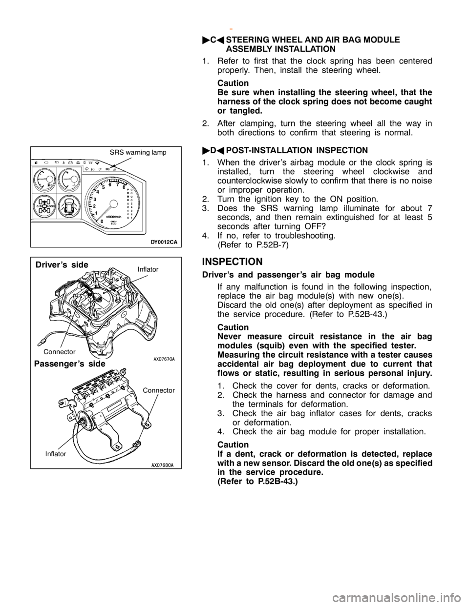
P
assen ger’s sid e C
onnecto r
I n fla to r C
onnecto r
w
ww.W ork sh opM an uals .c o .u k
P urc h ased f r o m w ww.W ork sh opM an uals .c o .u k
Page 1539 of 1839
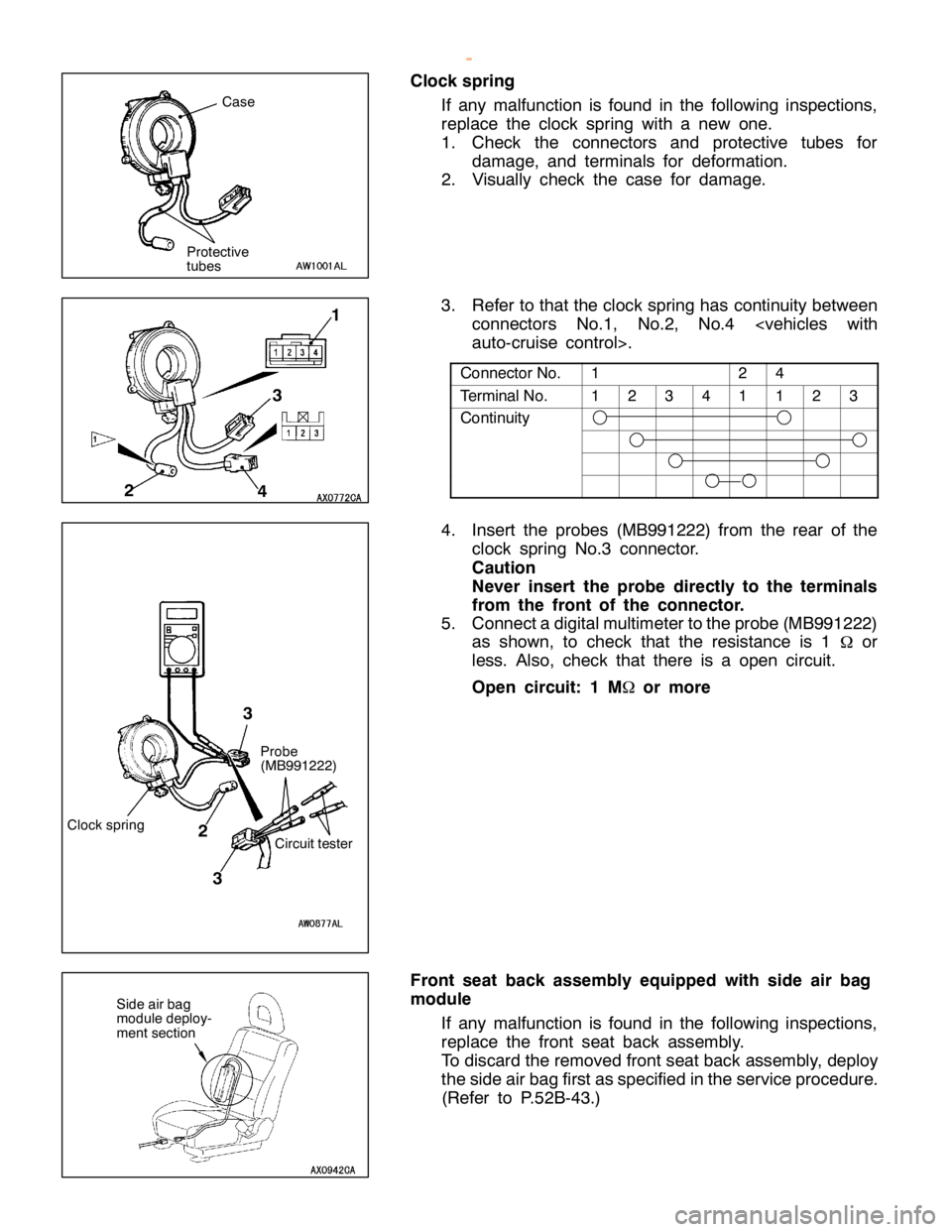
1 2 4
T
e rm in alN o. 1 2 3 4 1 1 2 3
C
ontin uit y P
ro be
( M B991222)
C ir c u it te ste r
3
2 3
Page 1540 of 1839
SRS -Air Bag Modules and Clock Spring52B-40
Caution
Never measure circuit resistance in the side air bag
modules (squib) even with the specified tester.
Measuring the circuit resistance with a tester causes
accidental air bag deployment due to current that
flows or static, resulting in serious personal injury.
1. Check the side air bag module deployment section
for dents and deformation.
2. Check the harness and connector for damage and
the terminals for deformation.
www.WorkshopManuals.co.uk
Purchased from www.WorkshopManuals.co.uk
Trending: suspension, turn signal bulb, starter relay, battery, automatic transmission, sport mode, dimensions


