MITSUBISHI MONTERO 2000 Service Repair Manual
Manufacturer: MITSUBISHI, Model Year: 2000, Model line: MONTERO, Model: MITSUBISHI MONTERO 2000Pages: 1839, PDF Size: 29.19 MB
Page 1571 of 1839

CHASSIS ELECTRICAL
Click on the applicable bookmark to selected the required model year.
www.WorkshopManuals.co.uk
Purchased from www.WorkshopManuals.co.uk
Page 1572 of 1839

54A-2
CHASSIS
ELECTRICAL
CONTENTS
BATTERY 4
..............................
SERVICE SPECIFICATIONS 4..................
ON-VEHICLE SERVICE 4......................
Electrolyte Level and Specific Gravity Check 4..
Charging 5.................................
Battery Test 5...............................
IGNITION SWITCH AND IMMOBILIZER
SPECIAL TOOLS 6............................
TROUBLESHOOTING 6........................
IGNITION SWITCH AND
IMMOBILIZER-ECU 11.........................
IGNITION SWITCH AND IMMOBILIZER
<4D56> 14...............................
SPECIAL TOOLS 14...........................
TROUBLESHOOTING 14.......................
IGNITION SWITCH AND IMMOBILIZER-ECU
19 ............................................
COMBINATION METER 23................
SERVICE SPECIFICATIONS 23.................
SEALANTS 24................................
SPECIAL TOOLS 24...........................
TROUBLESHOOTING 24.......................
ON-VEHICLE SERVICE 30.....................
Speedometer Check 30......................
Tachometer Check 30........................
Fuel Gauge Unit Check 31....................Engine Coolant Temperature Gauge Unit Check
32 .........................................
COMBINATION METER 33.....................
HEADLAMP ASSEMBLY 36...............
SERVICE SPECIFICATIONS 36.................
SPECIAL TOOLS 36...........................
TROUBLESHOOTING 36.......................
ON-VEHICLE SERVICE 36.....................
Headlamp Aiming Adjustment 36..............
Luminance Measurement 38..................
Headlamp Bulb Replacement 39...............
HEADLAMP ASSEMBLY 40....................
FOG LAMPS 41..........................
SERVICE SPECIFICATIONS 41.................
SPECIAL TOOLS 41...........................
TROUBLESHOOTING 41.......................
ON-VEHICLE SERVICE 41.....................
Fog Lamp Aiming Check 41...................
FOG LAMPS 44...............................
SIDE TURN-SIGNAL LAMPS 45...........
SPECIAL TOOLS 45...........................
SIDE TURN-SIGNAL LAMPS 46................
ROOM LAMP 46.........................
TROUBLESHOOTING 46.......................
CONTINUED ON NEXT PAGE
www.WorkshopManuals.co.uk
Purchased from www.WorkshopManuals.co.uk
Page 1573 of 1839

54A-3
ON-VEHICLE SERVICE 46......................
Room Lamp Delay-off Time Adjustment
Procedure 46...............................
REAR COMBINATION LAMP 47...........
SPECIAL TOOLS 47...........................
TROUBLESHOOTING 47.......................
REAR COMBINATION LAMP 47................
HIGH-MOUNTED STOP LAMP 48.........
COLUMN SWITCH 48....................
SPECIAL TOOLS 48...........................
COLUMN SWITCH 48..........................
HAZARD WARNING LAMP SWITCH 50....
SPECIAL TOOLS 50...........................
HAZARD WARNING LAMP SWITCH 50.........
HORN 51................................
CIGARETTE LIGHTER 51.................
ACCESSORY SOCKET 51................
RHEOSTAT 52...........................
CLOCK OR CENTER DISPLAY 53........
TROUBLESHOOTING 53.......................
CLOCK OR CENTER DISPLAY 67..............
RADIO/TAPE PLAYER 68.................
TROUBLESHOOTING 68.......................
RADIO AND CD AUTO CHANGER 81..........
FRONT SPEAKERS 82...................
REAR SPEAKERS 82.....................
ANTENNA83 ............................DEFOGGER 86...........................
TROUBLESHOOTING
ON-VEHICLE SERVICE 86.....................
Printed Heater Check 86.....................
Defogger Relay Continuity Check 86...........
DEFOGGER SWITCH 87.......................
SMART WIRING SYSTEM (SWS)
Refer to GROUP 54B ....................
RADIATOR (RADIATOR FAN MOTOR)
Refer to GROUP 14 ......................
AUTOMATIC TRANSMISSION
Refer to GROUP 23 ......................
ANTI-LOCK BRAKE SYSTEM (ABS)
Refer to GROUP 35B ....................
DOOR HANDLE LATCH (DOOR LOCK)
Refer to GROUP 42 ......................
DOOR GLASS-REGULATOR (POWER
WINDOWS)
Refer to GROUP 42 ......................
KEYLESS ENTRY SYSTEM
Refer to GROUP 42 ......................
WINDSHIELD WIPER/WASHER
Refer to GROUP 51 ......................
REAR WIPER/WASHER
Refer to GROUP 51 ......................
SRS AIRBAG Refer to GROUP 52B......
HEATER Refer to GROUP 55.............
AIR CONDITIONER Refer to GROUP 55...
www.WorkshopManuals.co.uk
Purchased from www.WorkshopManuals.co.uk
Page 1574 of 1839
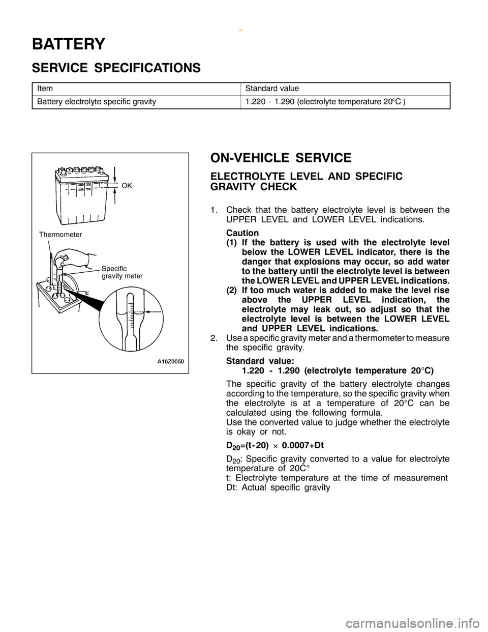
S
ta ndard va lu e B
atte ry ele ctr o ly te sp ecif ic gra vit y 1
.2 20 -1.2 90 (e le ctr o ly te te m pera tu re 20°C ) S
pecif ic
g ra vit y m ete r T
herm om ete r w
ww.W ork sh opM an uals .c o .u k
P urc h ased f r o m w ww.W ork sh opM an uals .c o .u k
Page 1575 of 1839
CHASSIS ELECTRICAL-Battery54A-5
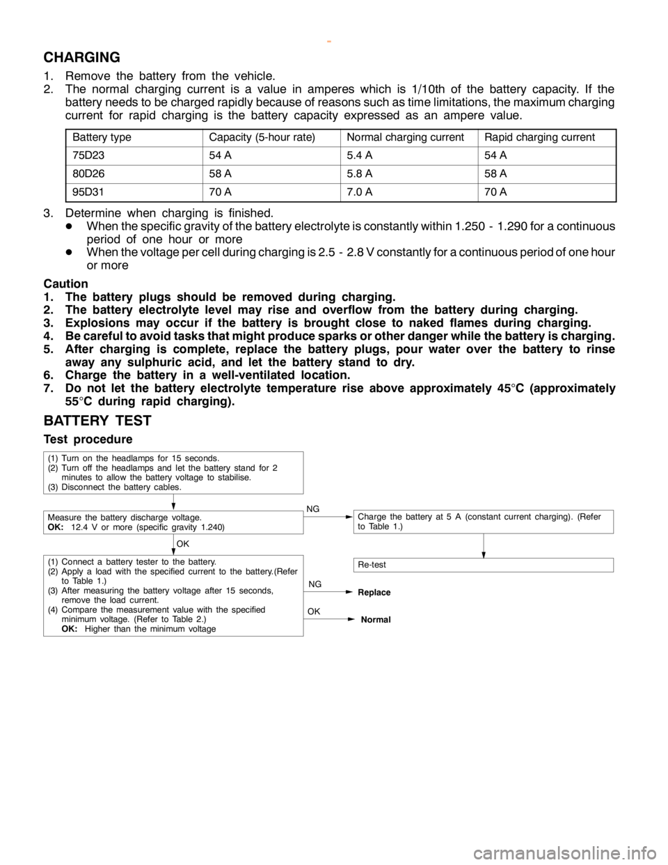
CHARGING
1. Remove the battery from the vehicle.
2. The normal charging current is a value in amperes which is 1/10th of the battery capacity. If the
battery needs to be charged rapidly because of reasons such as time limitations, the maximum charging
current for rapid charging is the battery capacity expressed as an ampere value.
Battery typeCapacity (5-hour rate)Normal charging currentRapid charging current
75D2354 A5.4 A54 A
80D2658 A5.8 A58 A
95D3170 A7.0 A70 A
3. Determine when charging is finished.
DWhen the specific gravity of the battery electrolyte is constantly within 1.250 - 1.290 for a continuous
period of one hour or more
DWhen the voltage per cell during charging is 2.5 - 2.8 V constantly for a continuous period of one hour
or more
Caution
1. The battery plugs should be removed during charging.
2. The battery electrolyte level may rise and overflow from the battery during charging.
3. Explosions may occur if the battery is brought close to naked flames during charging.
4. Be careful to avoid tasks that might produce sparks or other danger while the battery is charging.
5. After charging is complete, replace the battery plugs, pour water over the battery to rinse
away any sulphuric acid, and let the battery stand to dry.
6. Charge the battery in a well-ventilated location.
7. Do not let the battery electrolyte temperature rise above approximately 45
°C (approximately
55
°C during rapid charging).
BATTERY TEST
Test procedure
OK
NG
Replace
Re-test
OK
Normal
(1) Connect a battery tester to the battery.
(2) Apply aloadwith the specified current to the battery.(Refer
to Table 1.)
(3) After measuring the battery voltage after 15 seconds,
remove the loadcurrent.
(4) Compare the measurement value with the specified
minimum voltage.(Refer to Table 2.)
OK:Higher than the minimum voltage
Measure the battery discharge voltage.
OK:12.4 V or more (specific gravity 1.240)NGCharge the battery at 5 A (constant current charging). (Refer
to Table 1.)
(1) Turn on the headlamps for 15 seconds.
(2) Turn off the headlamps and let the battery stand for 2
minutes to allow the battery voltage to stabilise.
(3) Disconnect the battery cables.
www.WorkshopManuals.co.uk
Purchased from www.WorkshopManuals.co.uk
Page 1576 of 1839
![MITSUBISHI MONTERO 2000 Service Repair Manual 7
5D 23 8
0D 26 9
5D 31 C
harg in g tim e when fu lly dis ch arg ed [5 A co nsta nt
c u rre ntch arg in g] (H ) 1
1 1
2 1
4 L
oad cu rre nt(A ) 2
60 2
81 3
11 2
1 or
m ore 1
6 -20 1
0 -15 4
-9 –
1 - MITSUBISHI MONTERO 2000 Service Repair Manual 7
5D 23 8
0D 26 9
5D 31 C
harg in g tim e when fu lly dis ch arg ed [5 A co nsta nt
c u rre ntch arg in g] (H ) 1
1 1
2 1
4 L
oad cu rre nt(A ) 2
60 2
81 3
11 2
1 or
m ore 1
6 -20 1
0 -15 4
-9 –
1 -](/img/19/57331/w960_57331-1575.png)
7
5D 23 8
0D 26 9
5D 31 C
harg in g tim e when fu lly dis ch arg ed [5 A co nsta nt
c u rre ntch arg in g] (H ) 1
1 1
2 1
4 L
oad cu rre nt(A ) 2
60 2
81 3
11 2
1 or
m ore 1
6 -20 1
0 -15 4
-9 –
1 -3 –
1 -–1 –
12 -–1 –
18
- –13 M
in im um vo lt -
a ge (V ) 9
.6 9
.5 9
.4 9
.3 9
.1 8
.9 8
.7 8
.5 N
o. N
am e A
pplic a tio n M
B991502 M
UT-II Sub as-
s e m bly C
heckin g th e ETA C S-E C U in put sig nals M
B990784 O
rn am entre m ove r I
n str u m ent panel under co ve r and co lu m n
c o ve r re m ova l
Page 1577 of 1839
CHASSIS ELECTRICAL-Ignition Switch and Immobilizer
DIAGNOSIS CODE MEMORY ERASING PROCEDURE
Refer to GROUP 00 - How to Use Troubleshooting/Inspection Service Points.
INSPECTION USING SIMPLE CHECK DIAGNOSIS MODE
1. Change to Simple Check Diagnosis mode and activate switch diagnosis mode.
(Refer to GROUP 00 - How to Use Troubleshooting/Inspection Service Points.)
2. In this condition, the input signals for the following switches can be checked.
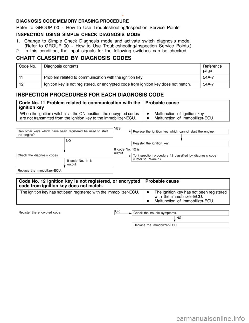
CHART CLASSIFIED BY DIAGNOSIS CODES
Code No.Diagnosis contentsReference
page
11Problem related to communication with the ignition key54A-7
12Ignition key is not registered, or encrypted code from ignition key does not match.54A-7
INSPECTION PROCEDURES FOR EACH DIAGNOSIS CODE
Code No. 11 Problem related to communication with the
ignition keyProbable cause
When the ignition switch is at the ON position, the encrypted codes
are not transmitted from the ignition key to the immobilizer-ECU.D
Malfunction of ignition key
D
Malfunction of immobilizer-ECU
YES
NOCan otherkeys which havebeen registered beused to start
the engine?
If code No. 12 is
output
Check the diagnosis codes.To inspection procedure 12 classified by diagnosis code
(Refer to P.54A-7.)
Replace the immobilizer-ECU.
Register the ignition key.
If code No. 11 is
output
Replace the ignition key which cannot start the engine.
Code No. 12 Ignition key is not registered, or encrypted
code from ignition key does not match.Probable cause
The ignition key has not been registered with the immobilizer-ECU.D
The ignition key has not been registered
with the immobilizer-ECU.
D
Malfunction of immobilizer-ECU
OK
NG
Replace the immobilizer-ECU.
Check the trouble symptoms.Register the encrypted code.
www.WorkshopManuals.co.uk
Purchased from www.WorkshopManuals.co.uk
Page 1578 of 1839
CHASSIS ELECTRICAL-Ignition Switch and Immobilizer
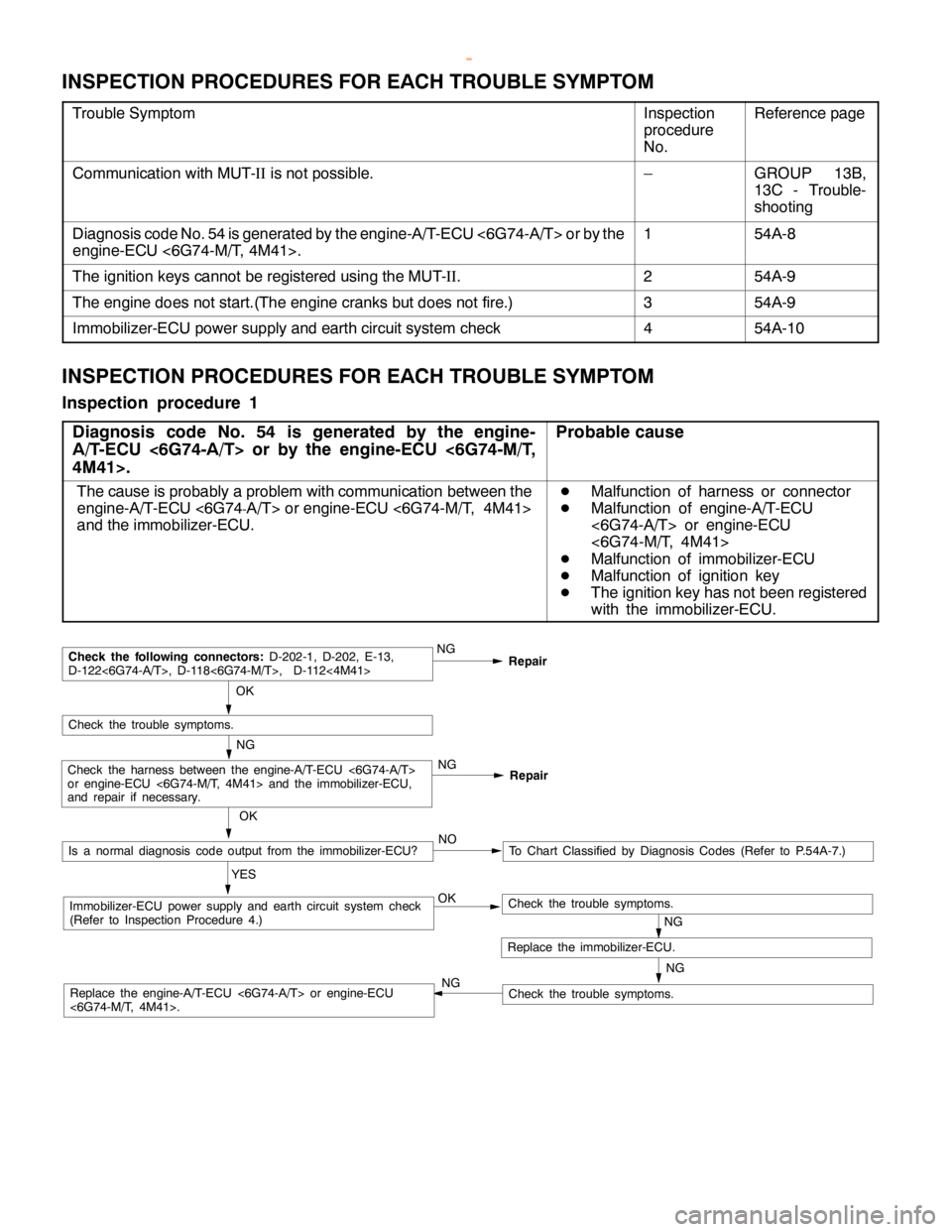
INSPECTION PROCEDURES FOR EACH TROUBLE SYMPTOM
Trouble SymptomInspection
procedure
No.Reference page
Communication with MUT-IIis not possible.–GROUP 13B,
13C - Trouble-
shooting
Diagnosis code No. 54 is generated by the engine-A/T-ECU <6G74-A/T> or by the
engine-ECU <6G74-M/T, 4M41>.154A-8
The ignition keys cannot be registered using the MUT-II.254A-9
The engine does not start.(The engine cranks but does not fire.)354A-9
Immobilizer-ECU power supply and earth circuit system check454A-10
INSPECTION PROCEDURES FOR EACH TROUBLE SYMPTOM
Inspection procedure 1
Diagnosis code No. 54 is generated by the engine-
A/T-ECU <6G74-A/T> or by the engine-ECU <6G74-M/T,
4M41>.
Probable cause
The cause is probably a problem with communication between the
engine-A/T-ECU <6G74
-A/T> orengine-ECU <6G74-M/T, 4M41>
and the immobilizer-ECU.
D
Malfunction of harness or connector
D
Malfunction of engine-A/T-ECU
<6G74-A/T> or engine-ECU
<6G74-M/T, 4M41>
D
Malfunction of immobilizer-ECU
D
Malfunction of ignition key
D
The ignition key has not been registered
with the immobilizer-ECU.
NG
NG OK
Immobilizer-ECU power supply and earth circuit system check
(Refer to Inspection Procedure 4.)
OK
Check the trouble symptoms.
NGRepair
NGCheck the following connectors:D-202-1, D-202, E-13,
D-122<6G74-A/T>, D-118<6G74-M/T>, D-112<4M41>
Repair
NGCheck the harness between the engine-A/T-ECU <6G74-A/T>
or engine-ECU <6G74-M/T, 4M41> and the immobilizer-ECU,
and repair if necessary.
Replace the immobilizer-ECU.
Check the trouble symptoms.
Check the trouble symptoms.Replace the engine-A/T-ECU <6G74-A/T> or engine-ECU
<6G74-M/T, 4M41>.OK
Is a normal diagnosis code output from the immobilizer-ECU?
YESTo Chart Classified by Diagnosis Codes (Refer to P.54A-7.) NO
NG
www.WorkshopManuals.co.uk
Purchased from www.WorkshopManuals.co.uk
Page 1579 of 1839
CHASSIS ELECTRICAL-Ignition Switch and Immobilizer
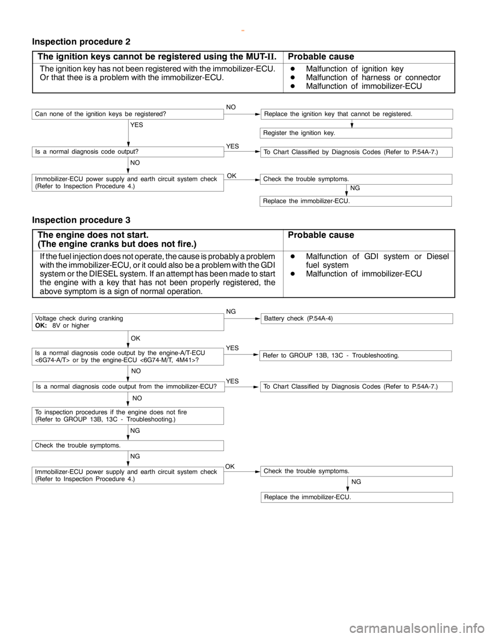
Inspection procedure 2
The ignition keys cannot be registered using the MUT-II.
Probable cause
The ignition key has not been registered with the immobilizer-ECU.
Or that thee is a problem with the immobilizer-ECU.D
Malfunction of ignition key
D
Malfunction of harness or connector
D
Malfunction of immobilizer-ECU
Register the ignition key.
YES
NO YESIs a normal diagnosis code output?
NOCan none of the ignitionkeys beregistered?Replace the ignition key that cannot be registered.
To Chart Classified by Diagnosis Codes (Refer to P.54A-7.)
OKImmobilizer-ECU power supply and earth circuit system check
(Refer to Inspection Procedure 4.)
NG
Replace the immobilizer-ECU.
Check the trouble symptoms.
Inspection procedure 3
The engine does not start.
(The engine cranks but does not fire.)
Probable cause
If the fuel injection does not operate, the cause is probably a problem
with the immobilizer-ECU, or it could also be a problem with the GDI
system or the DIESEL system. If an attempt has been made to start
the engine with a key that has not been properly registered, the
above symptom is a sign of normal operation.D
Malfunction of GDI system or Diesel
fuel system
D
Malfunction of immobilizer-ECU
NGBattery check (P.54A-4)
YES
NO
Refer to GROUP 13B, 13C - Troubleshooting.YES
NO
To Chart Classified by Diagnosis Codes (Refer to P.54A-7.)Is a normal diagnosis code output from the immobilizer-ECU?
OK
Voltage check during cranking
OK:8V or higher
NG
OKImmobilizer-ECU power supply and earth circuit system check
(Refer to Inspection Procedure 4.)
NG
Replace the immobilizer-ECU.
Check the trouble symptoms.
Check the trouble symptoms.
NG
To inspection procedures if the enginedoes not fire
(Refer to GROUP 13B, 13C - Troubleshooting.)
Is a normal diagnosis code output by the engine-A/T-ECU
<6G74-A/T> or by the engine-ECU <6G74-M/T, 4M41>?
www.WorkshopManuals.co.uk
Purchased from www.WorkshopManuals.co.uk
Page 1580 of 1839
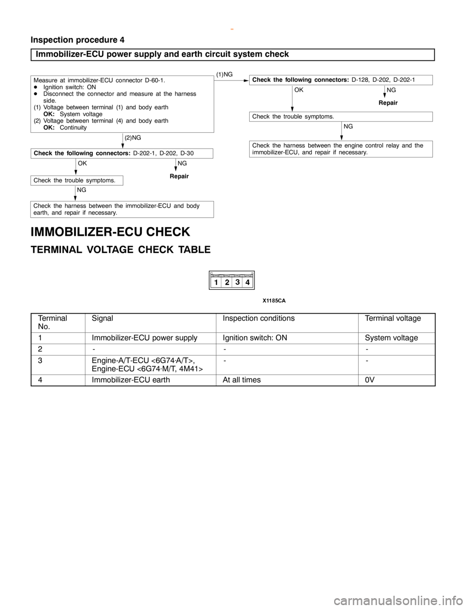
C
heck th e harn ess betw een th e engin e co ntr o l re la y and th e
i m mobiliz e r-E C U, and re pair if nece ssa ry . O
K C
heck th e tr o uble sym pto m s. (
2 )N G O
K C
heck th e tr o uble sym pto m s. C
heck th e harn ess betw een th e im mobiliz e r-E C U and body
e arth , and re pair if nece ssa ry .
I M MOBIL IZ E R -E C U CHEC K
T E R M IN AL VO LTA G E CHEC K TA BLE S
ig nal I
n sp ectio n co ndit io ns T
e rm in alvo lt a ge 1 I
m mobiliz e r-E C U pow er su pply I
g nit io n sw it c h : O N S
yste m vo lt a ge 2 - - -
3 E
ngin e-A /T -E C U <6G 74 ×A /T >,
E ngin e-E C U <6G 74×M /T , 4M 41> - -
4 I
m mobiliz e r-E C U earth A
tall tim es 0
V