MITSUBISHI OUTLANDER SPORT 2014 3.G Owners Manual
Manufacturer: MITSUBISHI, Model Year: 2014, Model line: OUTLANDER SPORT, Model: MITSUBISHI OUTLANDER SPORT 2014 3.GPages: 384, PDF Size: 46.94 MB
Page 241 of 384
Loading information 6-10 Driving safety
6
NOTE
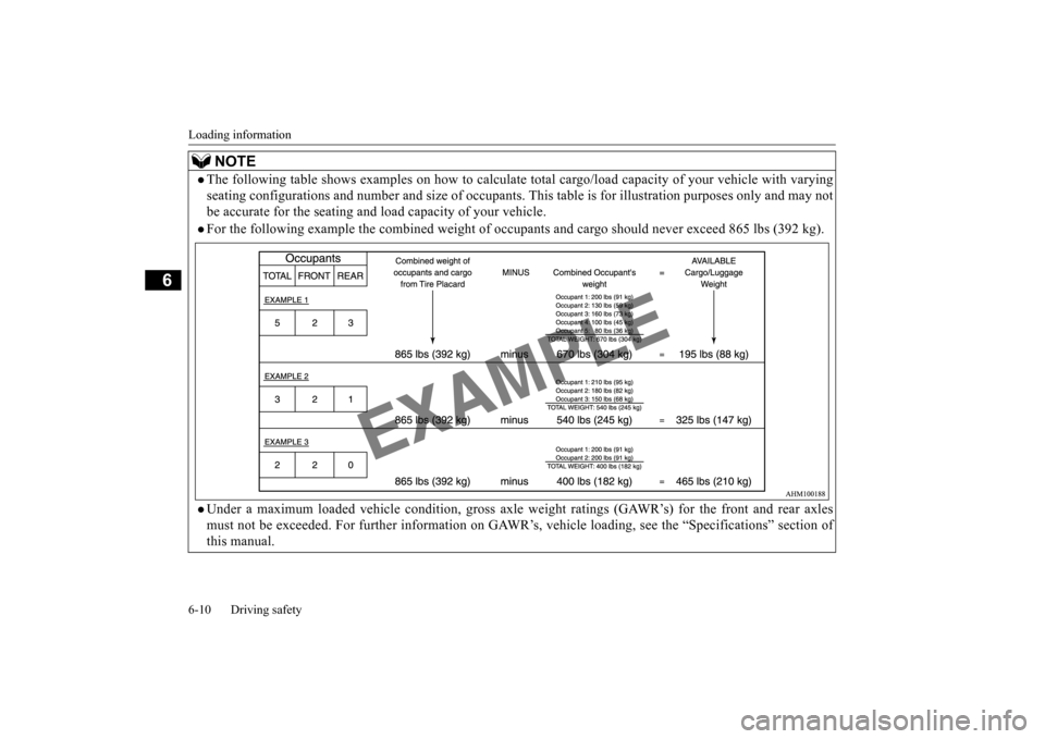
The following table shows examples on how
to calculate total cargo/load cap
acity of your vehicle with varying
seating configurations and number and size of occupants.
This table is for illustration purposes only and may not
be accurate for the seating and lo
ad capacity of your vehicle.
For the following example the combined weight of oc
cupants and cargo should never exceed 865 lbs (392 kg).
Under a maximum loaded vehicle condition, gross axle
weight ratings (GAWR’s) for the front and rear axles
must not be exceeded. For further information on GAWR
’s, vehicle loading, see the “Specifications” section of
this manual.
BK0202700US.bo
ok 10 ページ 2013年3月28日 木曜日 午前11時54分
Page 242 of 384
Cargo loads
Driving safety 6-11
6
N00629700435 N00630300040
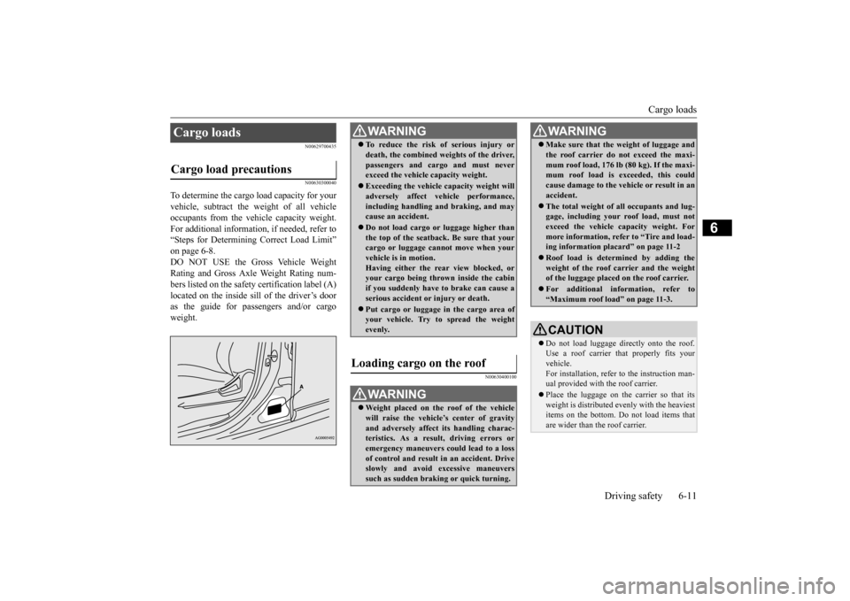
To determine the cargo load capacity for your vehicle, subtract the weight of all vehicleoccupants from the vehicle capacity weight. For additional information, if needed, refer to “Steps for Determining Correct Load Limit”on page 6-8.DO NOT USE the Gross Vehicle Weight Rating and Gross Axle Weight Rating num- bers listed on the safety certification label (A)located on the inside sill of the driver’s door as the guide for passengers and/or cargo weight.
N00630400100
Cargo loads Cargo load precautions
WA R N I N G To reduce the risk of serious injury or death, the combined weights of the driver, passengers and cargo and must never exceed the vehicle capacity weight. Exceeding the vehicle capacity weight will adversely affect vehicle performance, including handling and braking, and maycause an accident. Do not load cargo or luggage higher than the top of the seatback. Be sure that your cargo or luggage cannot move when your vehicle is in motion.Having either the rear view blocked, or your cargo being thrown inside the cabin if you suddenly have to brake can cause aserious accident or injury or death. Put cargo or luggage in the cargo area of your vehicle. Try to spread the weight evenly.
Loading cargo on the roof
WA R N I N G Weight placed on the roof of the vehicle will raise the vehicle’s center of gravity and adversely affect its handling charac-teristics. As a result, driving errors or emergency maneuvers could lead to a loss of control and result in an accident. Driveslowly and avoid excessive maneuvers such as sudden braking or quick turning.
Make sure that the weight of luggage and the roof carrier do not exceed the maxi- mum roof load, 176 lb (80 kg). If the maxi- mum roof load is exceeded, this could cause damage to the vehicle or result in anaccident. The total weight of all occupants and lug- gage, including your roof load, must not exceed the vehicle capacity weight. For more information, refer to “Tire and load-ing information placard” on page 11-2 Roof load is determined by adding the weight of the roof carrier and the weight of the luggage placed on the roof carrier. For additional information, refer to “Maximum roof load” on page 11-3.CAUTION Do not load luggage directly onto the roof. Use a roof carrier th
at properly fits your
vehicle. For installation, refer to the instruction man- ual provided with the roof carrier. Place the luggage on the carrier so that its weight is distributed evenly with the heaviest items on the bottom. Do not load items that are wider than the roof carrier.WA R N I N G
BK0202700US.bo
ok 11 ページ 2013年3月28日 木曜日 午前11時54分
Page 243 of 384
Cargo loads 6-12 Driving safety
6
N00630600085
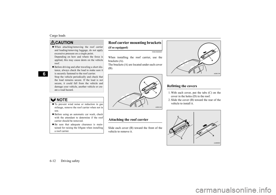
When installing the roof carrier, use the brackets (A). The brackets (A) are located under each cover(B). Slide each cover (B) toward the front of the vehicle to remove it.
1. With each cover, put the tabs (C) on the cover in the holes (D) in the roof. 2. Slide the cover (B) toward the rear of thevehicle to install it.
When attaching/removing the roof carrier and loading/removing luggage, do not apply excessive pressure on a single point. Depending on how and where the force is applied, this may cause dents on the vehicleroof. Before driving and after traveling a short dis- tance, always check the load to make sure it is securely fastened to the roof carrier. Stop the vehicle periodically and check thatthe load remains secure. If the load is not secure, it could fall from the vehicle and damage your vehicle, another vehicle or cre-ate a road hazard.NOTE
To prevent wind noise or reduction in gas mileage, remove the roof carrier when not in use. Before using an automatic car wash, check with the attendant to determine if the roofcarrier should be removed. Be sure that adequate clearance is main- tained for raising the liftgate when installing a roof carrier.CAUTION
Roof carrier mounting brackets
(if so equipped)Attaching the roof carrier
Refitting the covers
BK0202700US.bo
ok 12 ページ 2013年3月28日 木曜日 午前11時54分
Page 244 of 384
Trailer towing
Driving safety 6-13
6
N00629800306
Trailer towing
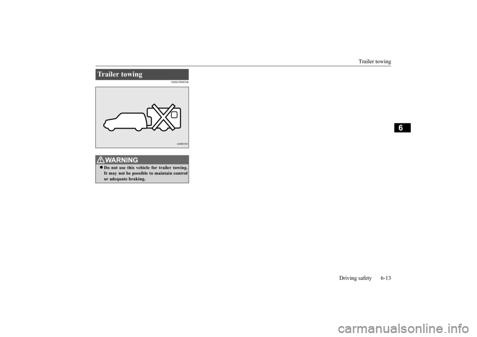
WA R N I N G Do not use this vehicle for trailer towing. It may not be possible to maintain controlor adequate braking.
BK0202700US.bo
ok 13 ページ 2013年3月28日 木曜日 午前11時54分
Page 245 of 384

BK0202700US.book 14 ページ 2013年3月28日 木曜日 午前11時54分
Page 246 of 384
7
Comfort controlsVents ..........................................
.......................................................7-2
Manual air conditioning-Type 1
(if so equipped) ............................7-4
Manual air conditioning-Type 2
(if so equipped) ............................7-9
Automatic air conditioning-Type1 (if so equipped) ......................7-14Automatic air conditioning-Type2 (if so equipped) ......................7-20 Important air conditioning op
erating tips .......................................7-25
Air purifier .......................
...............................................................7-25
AM/FM radio/CD player (if so equipped) .....................................7-26 Handling of Discs .
.................................................
........................7-29
Audio Files (MP3/WMA/
AAC) ....................................................7-31
Important Points on Safety fo
r the Customer ................................7-35
Operation Keys ...............
...............................................................7-36
Listen to Radio ......
.................................................
........................7-38
Listen to Satellite Radio (if so equipped) .......................................7-40 Listen to CDs ..................
...............................................................7-42
Listen to MP3s ......
.................................................
........................7-43
Listen to an iPod ...
.................................................
........................7-44
Listen to Audio Files on
a USB Device .........................................7-46
Listen to Bluetooth Audio (i
f so equipped) ....................................7-49
Display Indicator ..
.................................................
........................7-51
Audio Quality and Volume Balance Adjustment ...........................7-52 System Settings .....
.................................................
........................7-53
Troubleshooting ...............
...............................................................7-56
Antenna ................................................
...........................................7-58
General information about
your radio ............................................7-59
BK0202700US.bo
ok 1 ページ 2013年3月28日 木曜日 午前11時54分
Page 247 of 384
Vents 7-2 Comfort controls
7
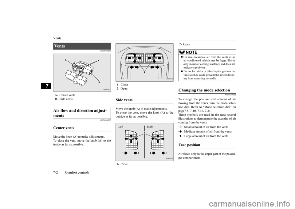
N00729900249 N00730200327
Move the knob (A) to make adjustments. To close the vent, move the knob (A) to the inside as far as possible.
Move the knob (A) to make adjustments. To close the vent, move the knob (A) to the outside as far as possible.
N00736400552
To change the position and amount of airflowing from the vents, turn the mode selec-tion dial. Refer to “Mode selection dial” on page7-5, 7-10, 7-16, 7-21. These symbols are used in the next severalillustrations to demonstrate the quantity of air coming from the vents. : Small amount of air from the vents : Medium amount of air from the vents : Large amount of air from the vents Air flows only to the up
per part of the passen-
ger compartment.
Ve n t s A- Center vents B- Side ventsAir flow and direction adjust- ments Center vents
1- Close 2- OpenSide vents 1- CloseLeft Right
2- Open
NOTE
On rare occasions, air from the vents of an air-conditioned vehicle may be foggy. This is only moist air cooling suddenly and does not indicate a problem. Do not let drinks or ot
her liquids get into the
vents as they could prevent the air condition-ing from operating normally.
Changing the mode selection Face position
BK0202700US.bo
ok 2 ページ 2013年3月28日 木曜日 午前11時54分
Page 248 of 384
Vents
Comfort controls 7-3
7
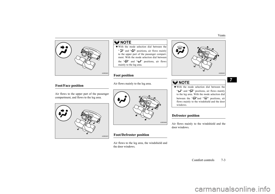
Air flows to the upper part of the passenger compartment, and flows to the leg area.
Air flows mainly to the leg area. Air flows to the leg area, the windshield and the door windows.
Air flows mainly to the windshield and the door windows.
Foot/Face position
NOTE
With the mode selection dial between the “ ” and “ ” positions, air flows mainly to the upper part of the passenger compart- ment. With the mode selection dial between the “ ” and “ ” positions, air flows mainly to the leg area.
Foot position Foot/Defroster position
NOTE
With the mode selection dial between the “ ” and “ ” positions, air flows mainly to the leg area. With the mode selection dial between the “ ”and “ ” positions, air flows mainly to the windshield and the door windows.
Defroster position
BK0202700US.bo
ok 3 ページ 2013年3月28日 木曜日 午前11時54分
Page 249 of 384
Manual air conditioning-T
ype 1 (if so equipped)
7-4 Comfort controls
7
N00730300331 N00730500258
N00736500175
When the ignition switch or the operation mode is in ON, select the blower speed byturning the blower speed selection dial. Turning the dial clockwise will increase the blower speed; turning the dial counterclock-wise will decrease it. When the dial is set to the “OFF” position, all fan-driven airflow will stop.
N00736600222
Turn the temperature control dial clockwiseto make the air warmer. Turn it counterclock-wise to make the air cooler.
Manual air conditioning- Ty p e 1
(if so equipped)
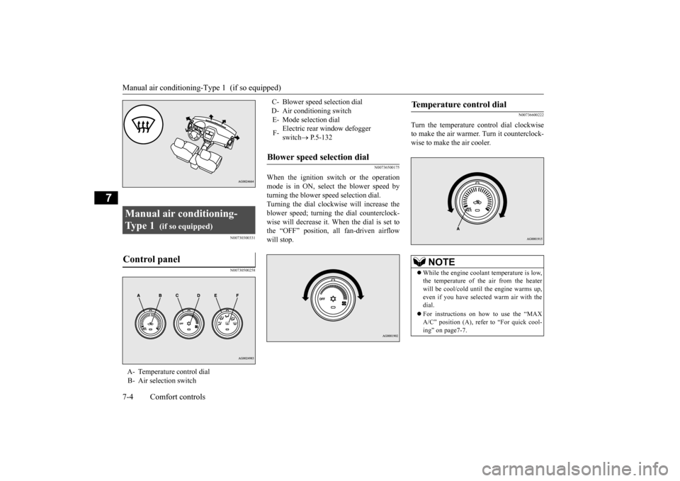
Control panel
A- Temperature control dial B- Air selection switch
C- Blower speed selection dial D- Air conditioning switchE- Mode selection dial F-
Electric rear window defogger switch
P.5-132
Blower speed selection dial
Temperature control dial
NOTE
While the engine coolant temperature is low, the temperature of the air from the heater will be cool/cold until the engine warms up, even if you have selected warm air with thedial. For instructions on how to use the “MAX A/C” position (A), refer to “For quick cool- ing” on page7-7.
BK0202700US.bo
ok 4 ページ 2013年3月28日 木曜日 午前11時54分
Page 250 of 384
Manual air conditioning-Type 1 (if so equipped)
Comfort controls 7-5
7
N00736700151
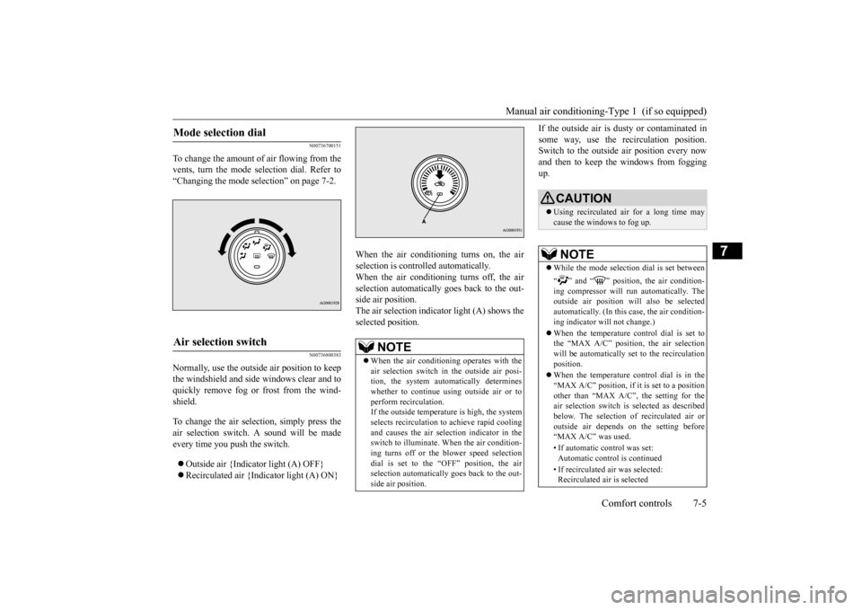
To change the amount of air flowing from the vents, turn the mode selection dial. Refer to“Changing the mode selection” on page 7-2.
N00736800383
Normally, use the outside air position to keepthe windshield and side windows clear and toquickly remove fog or frost from the wind- shield. To change the air selection, simply press the air selection switch. A sound will be madeevery time you push the switch. Outside air {Indicator light (A) OFF} Recirculated air {Indicator light (A) ON}
When the air conditioning turns on, the air selection is controlled automatically. When the air conditioning turns off, the airselection automatically goes back to the out- side air position. The air selection indicator light (A) shows theselected position.
If the outside air is dusty or contaminated in some way, use the recirculation position. Switch to the outside air position every now and then to keep th
e windows from fogging
up.
Mode selection dial
Air selection switch
NOTE
When the air conditioning operates with the air selection switch in
the outside air posi-
tion, the system automatically determineswhether to continue using outside air or to perform recirculation. If the outside temperature is high, the systemselects recirculation to achieve rapid cooling and causes the air selection indicator in the switch to illuminate. When the air condition-ing turns off or the blower speed selection dial is set to the “OFF” position, the air selection automatically goes back to the out-side air position.
CAUTION Using recirculated air for a long time may cause the windows to fog up.NOTE
While the mode selection dial is set between “ ” and “ ” position, the air condition- ing compressor will run automatically. The outside air position will also be selected automatically. (In this case, the air condition-ing indicator will not change.) When the temperature control dial is set to the “MAX A/C” position, the air selection will be automatically set to the recirculation position. When the temperature control dial is in the “MAX A/C” position, if it is set to a positionother than “MAX A/C”, the setting for the air selection switch is selected as described below. The selection of recirculated air oroutside air depends on the setting before “MAX A/C” was used. • If automatic control was set: Automatic control is continued • If recirculated air was selected: Recirculated air is selected
BK0202700US.bo
ok 5 ページ 2013年3月28日 木曜日 午前11時54分