MITSUBISHI PAJERO IV 2011 Owners Manual
Manufacturer: MITSUBISHI, Model Year: 2011, Model line: PAJERO IV, Model: MITSUBISHI PAJERO IV 2011Pages: 377, PDF Size: 29.43 MB
Page 331 of 377
Bulb capacity
E01003200014
When replacing a
bulb, use a new bulb with the
same wattage and colour.
Outside E01003302631
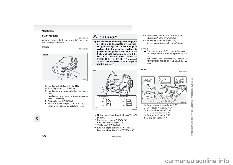
Front1- Headlamps, high-beam: 65 W (H9)
2- Front fog lamps*: 55 W (H11)
3-
Headlamps,
low beam with discharge lamp:
35 W (D2S)
Headlamps, low beam without discharge
lamp: 55 W (H11)
4- Position lamps: 5 W (W5W)
5- Front turn-signal lamps: 21 W (WY21W) Codes in parentheses indicate bulb types. CAUTION
l
On vehicles with discharge headlamps, do
not attempt to
disassemble or repair dis-
charge headlamps, and do not attempt to
replace their bulbs. A high voltage is
present in the power circuit and in the
bulbs and bulb terminals. To avoid the
risk of an electric shock, contact a
MITSUBISHI MOTORS Authorized
Service Point whenever repair or replace-
ment is necessary.
3-door models 5-door models
Rear
6- High-mounted stop
lamp
(bulb type)*: 16 W
(W16W)
7- Licence plate lamps: 5 W (W5W)
8- Rear fog lamp: 21 W (W21W)
9- Tail lamps*: 5 W (W5W)
10- Rear turn-signal lamps*: 21 W (WY21W)
11- Rear turn-signal lamps*: 21 W (WY21W) 12- Stop and tail lamps*: 21/5 W (W21/5W)
Stop lamps*: 21/5 W (W21/5W)
13- Reversing lamps: 21 W (W21W) Codes in parentheses indicate bulb types.
NOTE l On
vehicles
with LED type high-mounted
stop lamp, do not attempt to repair or replace
it.
For repair and replacement, contact a
MITSUBISHI MOTORS Authorized Service
Point.
Inside E01003401244 1- Luggage compartment lamp: 8 W
2- Door courtesy lamps: 3.4 W
3-
Vanity mirror lamps*:
3 W
4- Room & map lamps: 8 W
5- Rear personal lamps: 8 W
6- Glove box lamp: 1.4 W Maintenance
8-24
8
OBKE12E1
Page 332 of 377
Headlamps
E01003501199
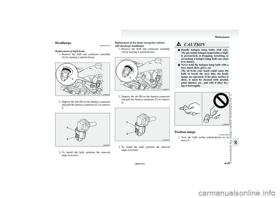
Replacement of high-beam 1. Remove the bulb
and connector assembly
(A) by turning it anticlockwise. 2. Depress the tab (B) on the harness connector
and pull
the harness connector (C) to remove
it. 3. To
install the bulb, perform the removal
steps in reverse. Replacement of low beam (except for vehicles
with discharge headlamps)
1.Remove the bulb
and connector assembly
(A) by turning it anticlockwise. 2. Depress the tab (B) on the harness connector
and pull
the harness connector (C) to remove
it. 3. To install the bulb, perform the removal
steps in reverse. CAUTION
l
Handle halogen lamp
bulbs with care.
The gas inside halogen lamp bulbs is high-
ly pressurized, so dropping, knocking, or
scratching a halogen lamp bulb can cause
it to shatter.
l Never hold the halogen lamp bulb with a
bare hand, dirty glove, etc.
The oil from your hand could cause the
bulb to break the next time the head-
lamps are operated. If the glass surface is
dirty, it must be cleaned with alcohol,
paint thinner, etc., and refit it after dry-
ing it thoroughly. Position lamps
E01003700471
1. Turn the bulb socket anticlockwise to re-
move it. Maintenance
8-25 8
OBKE12E1
Page 333 of 377
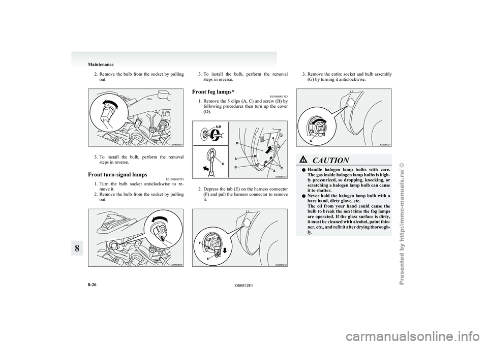
2. Remove the bulb from the socket by pulling
out. 3. To install the bulb, perform the removal
steps in reverse.
Front turn-signal lamps E01003800733
1. Turn
the
bulb socket anticlockwise to re-
move it.
2. Remove
the bulb from the socket by pulling
out. 3. To install the bulb, perform the removal
steps in reverse.
Front fog lamps* E01004001553
1. Remove the
5 clips (A, C) and screw (B) by
following procedures
then turn up the cover
(D). 2. Depress the tab (E) on the harness connector
(F) and
pull the harness connector to remove
it. 3. Remove the entire socket and bulb assembly
(G) by turning it anticlockwise. CAUTION
l
Handle halogen
lamp
bulbs with care.
The gas inside halogen lamp bulbs is high-
ly pressurized, so dropping, knocking, or
scratching a halogen lamp bulb can cause
it to shatter.
l Never hold the halogen lamp bulb with a
bare hand, dirty glove, etc.
The oil from your hand could cause the
bulb to break the next time the fog lamps
are operated. If the glass surface is dirty,
it must be cleaned with alcohol, paint thin-
ner, etc., and refit it after drying thorough-
ly. Maintenance
8-26
8
OBKE12E1
Page 334 of 377
4. To install the bulb, perform the removal
steps in reverse.
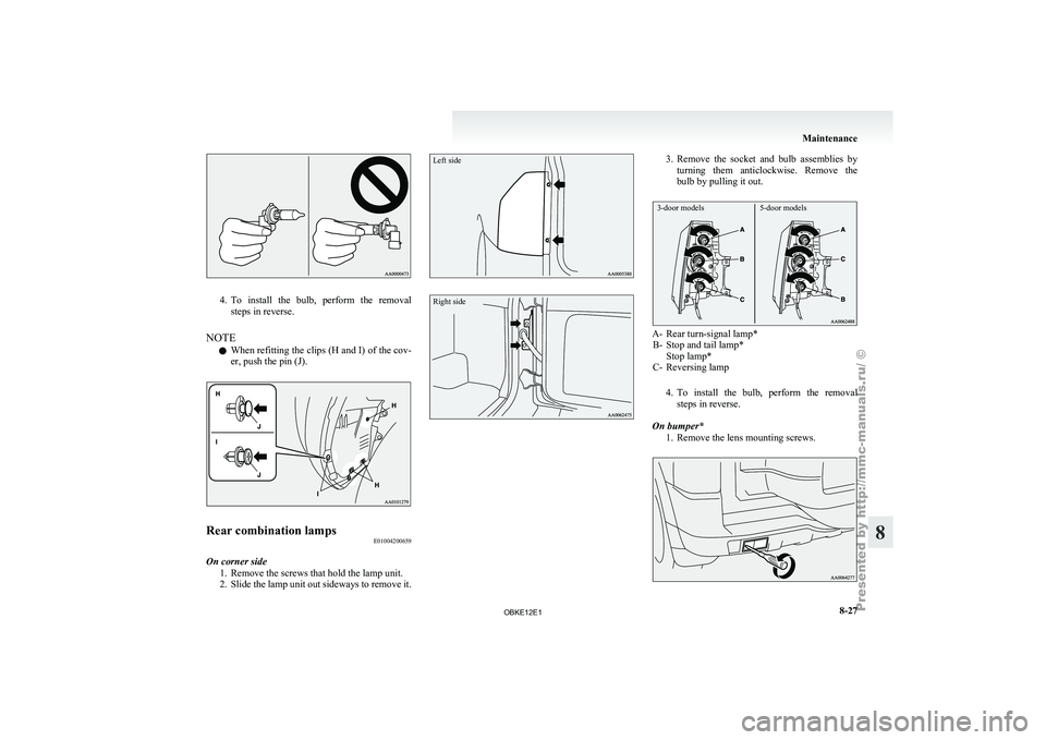
NOTE l When
refitting
the clips (H and I) of the cov-
er, push the pin (J). Rear combination lamps
E01004200659
On corner side 1.Remove the screws that hold the lamp unit.
2. Slide
the lamp unit out sideways to remove it.
Left side
Right side 3. Remove the socket and bulb assemblies by
turning them
anticlockwise. Remove the
bulb by pulling it out.
3-door models 5-door models A- Rear turn-signal lamp*
B- Stop and tail lamp* Stop lamp*
C- Reversing lamp
4.
To install the bulb, perform the removalsteps in reverse.
On bumper* 1. Remove the lens mounting screws. Maintenance
8-27 8
OBKE12E1
Page 335 of 377
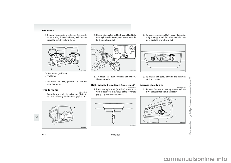
2. Remove the socket and bulb assembly togeth-
er by turning it anticlockwise, and then re-
move the bulb by pulling it out. D- Rear turn-signal lamp
E- Tail lamp
3. To install the
bulb, perform the removal
steps in reverse.
Rear fog lamp E01004100371
1. Open the spare wheel garnish (A). (Refer to
“To remove the spare wheel” on page 6-10). 2. Remove the socket and bulb assembly (B) by
turning it
anticlockwise, and then remove the
bulb by pulling it out. 3. To install the bulb, perform the removal
steps in reverse.
High-mounted stop lamp (bulb type)* E01004500535
1. Insert
a
straight blade (or minus) screwdriver
with a
cloth over at the edge of the cover and
pry gently to remove the cover. 2. Remove the socket and bulb assembly togeth-
er by
turning it anticlockwise, and then re-
move the bulb by pulling it out. 3. To install the bulb, perform the removal
steps in reverse.
Licence plate lamps E01004600709
1. Remove
the
lens mounting screws and re-
move the socket and bulb assembly. Maintenance
8-28
8
OBKE12E1
Page 336 of 377
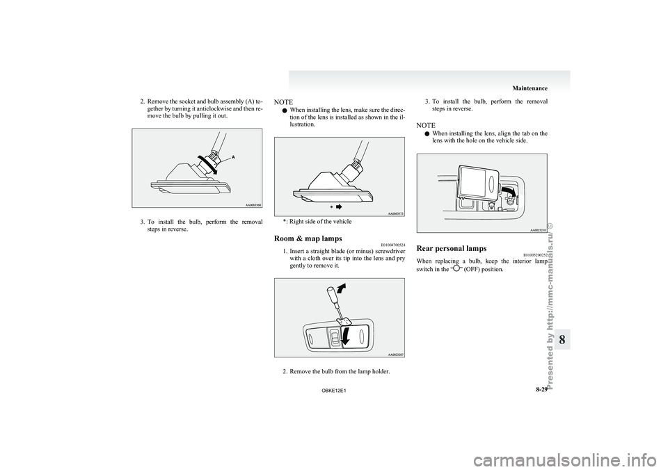
2. Remove the socket and bulb assembly (A) to-
gether by turning it anticlockwise and then re-
move the bulb by pulling it out. 3. To install the bulb, perform the removal
steps in reverse. NOTE
l When
installing the
lens, make sure the direc-
tion of the lens is installed as shown in the il-
lustration. *: Right side of the vehicle
Room & map lamps E01004700524
1. Insert a straight blade (or minus) screwdriver
with a
cloth over its tip into the lens and pry
gently to remove it. 2. Remove the bulb from the lamp holder.3. To install the bulb, perform the removal
steps in reverse.
NOTE l When installing
the lens, align the tab on the
lens with the hole on the vehicle side. Rear personal lamps
E01005200252
When replacing a bulb, keep the interior lamp
switch in the “ ” (OFF) position. Maintenance
8-29 8
OBKE12E1
Page 337 of 377
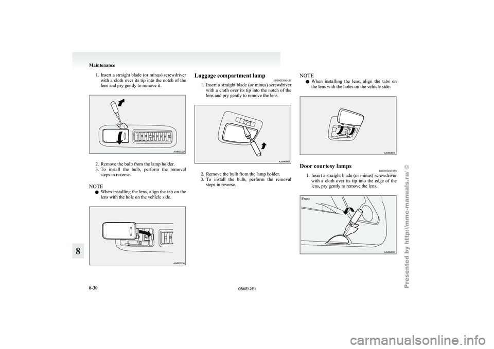
1. Insert a straight blade (or minus) screwdriver
with a cloth over its tip into the notch of the
lens and pry gently to remove it. 2. Remove the bulb from the lamp holder.
3. To install
the
bulb, perform the removal
steps in reverse.
NOTE l When installing the lens, align the tab on the
lens with the hole on the vehicle side. Luggage compartment lamp
E01005300439
1. Insert a straight
blade (or minus) screwdriver
with a cloth over its tip into the notch of the
lens and pry gently to remove the lens. 2. Remove the bulb from the lamp holder.
3. To
install the
bulb, perform the removal
steps in reverse. NOTE
l When
installing the
lens, align the tabs on
the lens with the holes on the vehicle side. Door courtesy lamps
E01005400339
1. Insert a straight blade (or minus) screwdriver
with a
cloth over its tip into the edge of the
lens, pry gently to remove the lens.
Front Maintenance
8-30
8
OBKE12E1
Page 338 of 377
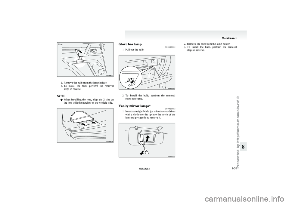
Rear2. Remove the bulb from the lamp holder.
3. To install
the
bulb, perform the removal
steps in reverse.
NOTE l When installing the lens, align the 2 tabs on
the lens with the notches on the vehicle side. Glove box lamp
E01006100232
1. Pull out the bulb. 2. To
install the bulb, perform the removal
steps in reverse.
Vanity mirror lamps* E01006200262
1. Insert
a
straight blade (or minus) screwdriver
with a
cloth over its tip into the notch of the
lens and pry gently to remove it. 2. Remove the bulb from the lamp holder.
3. To install the
bulb, perform the removal
steps in reverse. Maintenance
8-31 8
OBKE12E1
Page 339 of 377
OBKE12E1
Page 340 of 377
Vehicle labeling
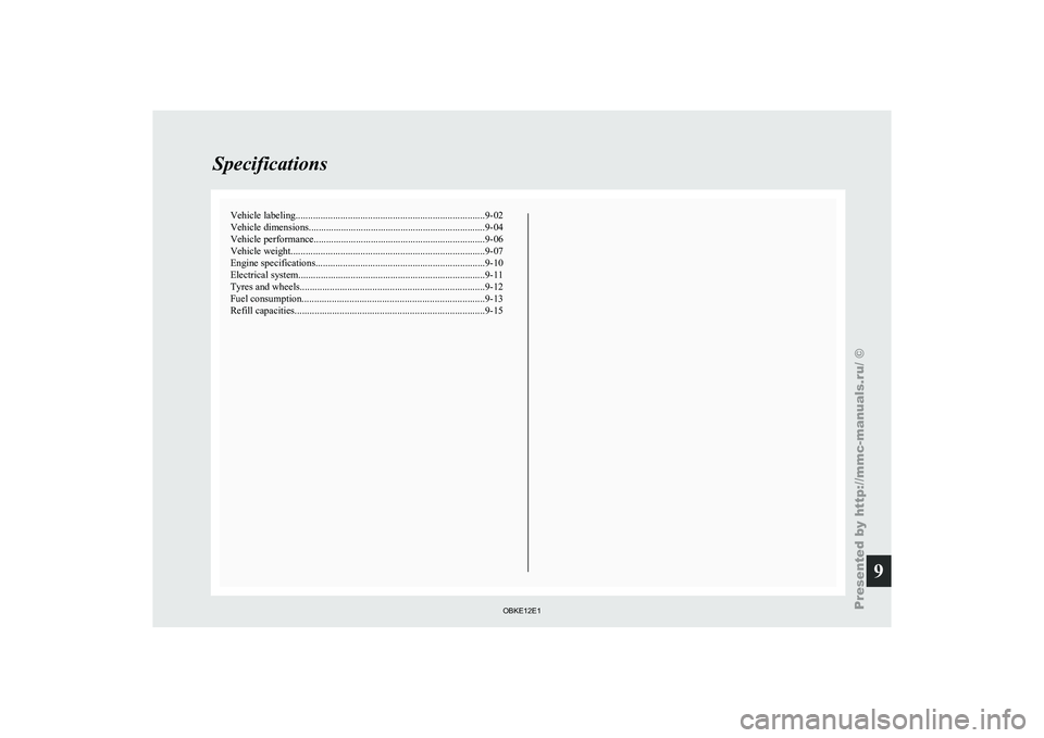
............................................................................ 9-02
Vehicle dimensions....................................................................... 9-04
Vehicle performance ..................................................................... 9-06
Vehicle weight .............................................................................. 9-07
Engine specifications .................................................................... 9-10
Electrical system ........................................................................... 9-11
Tyres and wheels
.......................................................................... 9-12
Fuel consumption ......................................................................... 9-13
Refill capacities ............................................................................ 9-15Specifications
9
OBKE12E1