MITSUBISHI SPYDER 1990 Service Repair Manual
Manufacturer: MITSUBISHI, Model Year: 1990, Model line: SPYDER, Model: MITSUBISHI SPYDER 1990Pages: 2103, PDF Size: 68.98 MB
Page 1711 of 2103
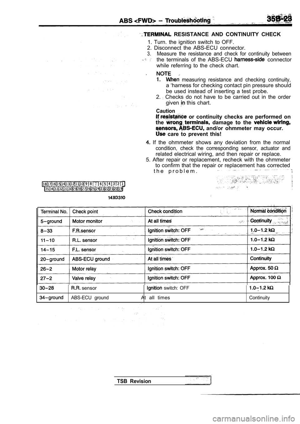
RESISTANCE AND CONTINUITY CHECK
1. Turn. the ignition switch to OFF.
2. Disconnect the ABS-ECU connector.
3.Measure the resistance and check for continuity bet ween
the terminals of the ABS-ECU connector
while referring to the check chart.
measuring resistance and checking continuity,
a ‘harness for checking contact pin pressure should
be used instead of inserting a test probe.
2.
Checks do not have to be carried out in the order
given
this chart.
Caution
or continuity checks are performed on
the
damage to the
and/or ohmmeter may occur.
care to prevent this!
If the ohmmeter shows any deviation from the norma l
condition, check the corresponding sensor, actuator and
related electrical wiring, and then repair or replace.
5. After repair or replacement, recheck with the oh mmeter
to confirm that the repair or replacement has corre cted
t h e p r o b l e m .
7
sensor switch: OFF
ABS-ECU groundAt all timesContinuity
TSB Revision
Page 1712 of 2103
On-vehicle. Service
Check connector
l
harness
ON-VEHICLE SERVICE
C a u t i o n
Use the specified brake fluid. Avoid using a mixture of
the specified brake fluid and other fluid.
Specified brake fluid:
or
MASTER CYLINDER BLEEDING
Refer to GROUP
On-vehicle Service.
BRAKE LINE BLEEDING
Refer to GROUP
On-vehicle Service.
Caution
For with ABS, be sure to filter/strain the brake
fluid ‘being added to the master cylinder reservoir tank.
Debris may damage the HU.
OPERATION CHECK35200130101
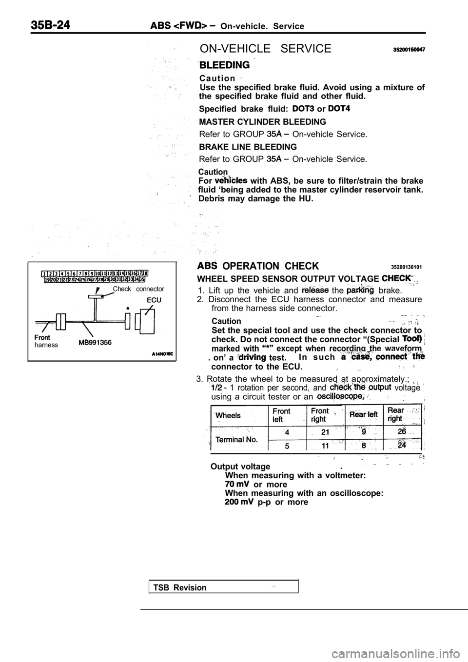
WHEEL SPEED SENSOR OUTPUT VOLTAGE
1. Lift up the vehicle and the brake.
2. Disconnect the ECU harness connector and measure from the harness side connector.
Caution
Set the special tool and use the check connector to
check. Do not connect the connector “(Special
marked with except when recording the waveform
. on’ a test. I n s u c h
connector to the ECU.
3. Rotate the wheel to be measured at approximately
.;
1 rotation per second, and voltage
using a circuit tester or an
Output voltage.
When measuring with a voltmeter:
or more
When measuring with an oscilloscope:
p-p or more
TSB Revision
Page 1713 of 2103
Service
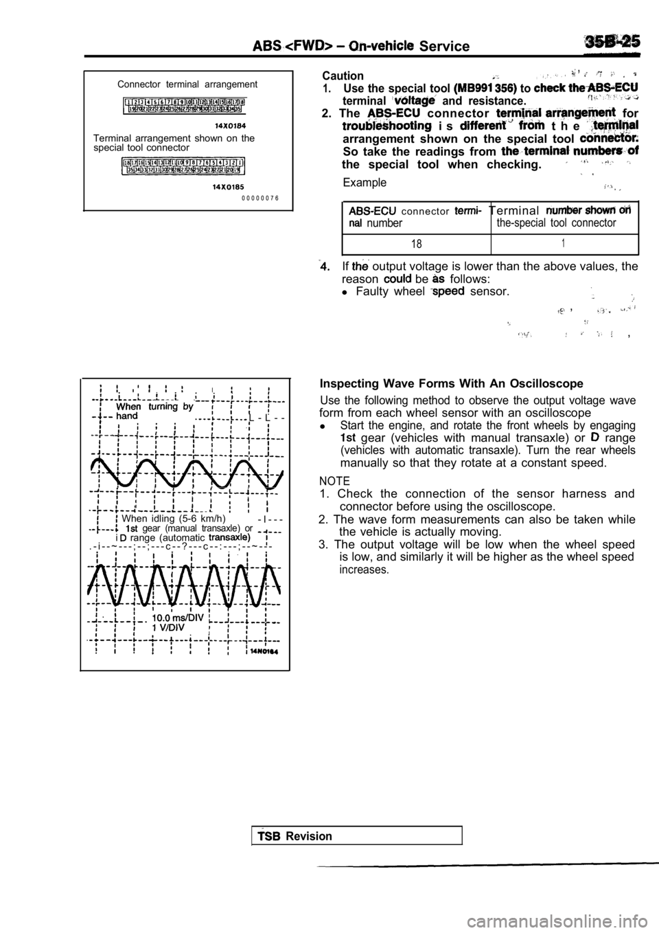
Connector terminal arrangement
Terminal arrangement shown on thespecial tool connector
0 0 0 0 0 0 7 6
L - L - -
,
I
When idling (5-6 km/h) gear (manual transaxle) or- I - - -
. - i - - ~ - - - ; - - ; - - - c - - ? - - - c - - : - - - ; - - ~ - - - i range (automatic
,Caution,
1.Use the special tool to
terminal and resistance.
2. The connector for
i s t h e
arrangement shown on the special tool
So take the readings from
the special tool when checking.
Example
c o n n e c t o r Terminal
numberthe-special tool connector
181
If output voltage is lower than the above values, the
reason
be follows:
l Faulty wheel
sensor.
,
,
Inspecting Wave Forms With An Oscilloscope
Use the following method to observe the output volt age wave
form from each wheel sensor with an oscilloscope
l
Start the engine, and rotate the front wheels by en gaging
gear (vehicles with manual transaxle) or range
(vehicles with automatic transaxle). Turn the rear wheels
manually so that they rotate at a constant speed.
NOTE
1. Check the connection of the sensor harness and
connector before using the oscilloscope.
2. The wave form measurements can also be taken whi le
the vehicle is actually moving.
3. The output voltage will be low when the wheel sp eed
is low, and similarly it will be higher as the whee l speed
increases.
Revision
Page 1714 of 2103
On-vehicle Service .
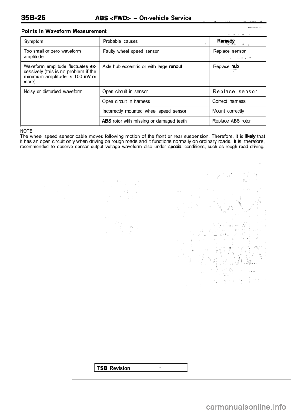
Points In Waveform Measurement
SymptomProbable causes
Too small or zero waveform
Faulty wheel speed sensor Replace sensor
amplitude
. .
Waveform amplitude fluctuates Axle hub eccentric or with large
cessively (this is no problem if the
Replace
minimum amplitude is 100 or
more)
Noisy or disturbed waveform Open circuit in sensorR e p l a c e s e n s o r
Open circuit in harness Correct harness
Incorrectly mounted wheel speed sensor Mount correctly
rotor with missing or damaged teethReplace ABS rotor
NOTE
The wheel speed sensor cable moves following motion
of the front or rear suspension. Therefore, it is that
it has an open circuit only when driving on rough r oads and it functions normally on ordinary roads.
is, therefore,
recommended to observe sensor output voltage wavefo rm also under conditions, such as rough road driving.
Revision
Page 1715 of 2103
A B S
HYDRAULIC UNIT (HU) CHECK
Caution
35200170111
Turn the ignition switch off before connecting ordisconnecting the scan tool.
1.
up the vehicle and support the vehicle with rigid
racks placed at the specified jack-up points or pla ce the
wheels which are checked on the rollers of the brak ing
force tester.
Caution
1.The roller of the braking force tester and the tire
be dry during testing.
2.When testing the front brakes, apply the parking
brake, and when testing the rear brakes, stop the
front by chocking them.
2.Release the parking brake, and feel the drag force (drag
torque) on each road wheel.. __
When using the braking force tester, take a reading of’
the brake drag force.
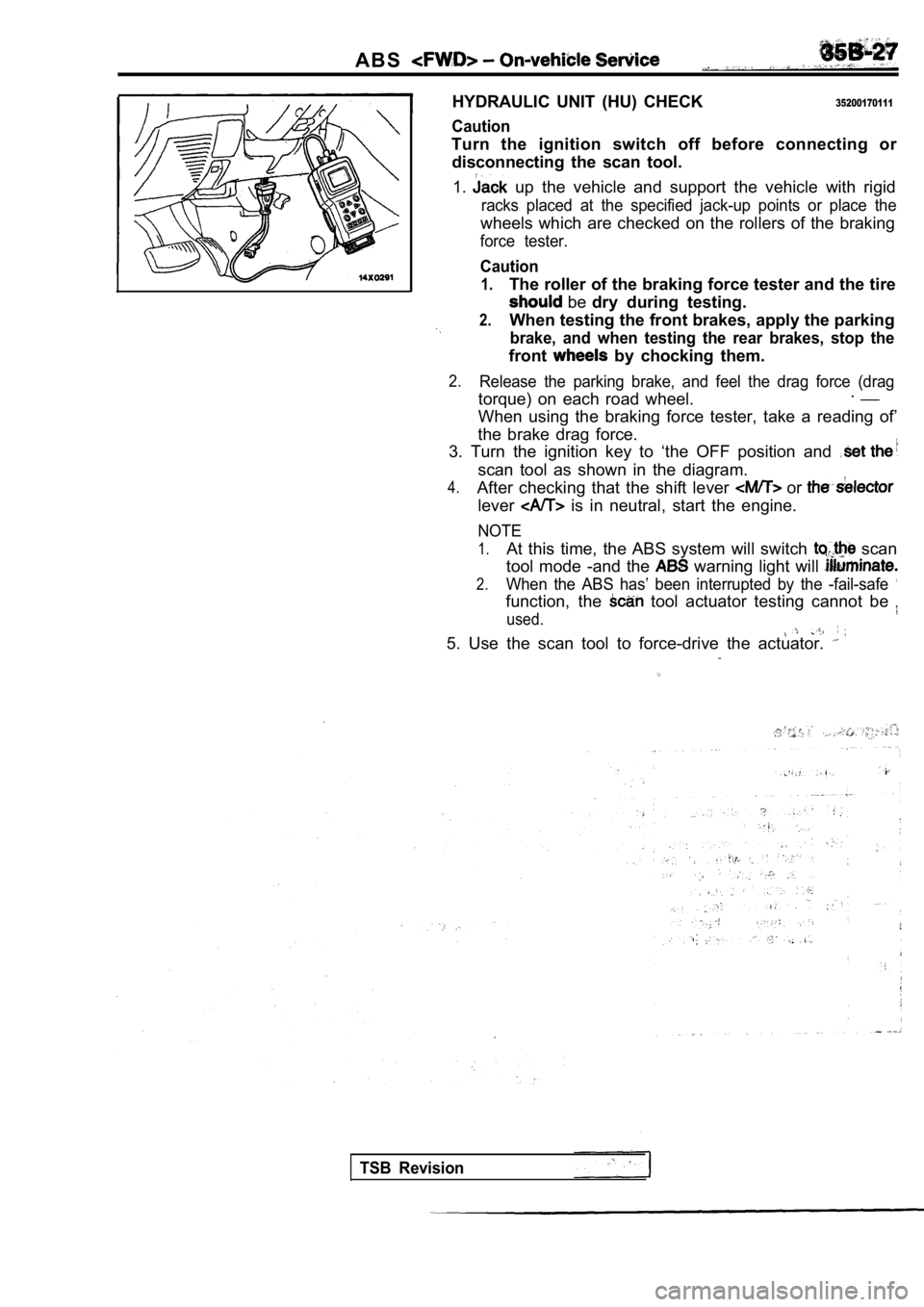
3. Turn the ignition key to ‘the OFF position and
scan tool as shown in the diagram.
4.After checking that the shift lever or
lever is in neutral, start the engine.
NOTE
1.At this time, the ABS system will switch scan
tool mode -and the
warning light will
2.When the ABS has’ been interrupted by the -fail-saf e
function, the tool actuator testing cannot be
used.
5. Use the scan tool to force-drive the actuator.
TSB Revision
Page 1716 of 2103
ABS On-vehicle Service
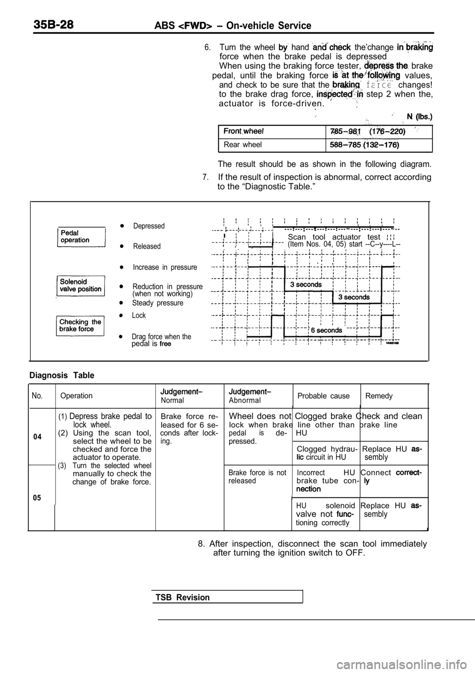
6.Turn the wheel hand the’change
force when the brake pedal is depressed
When using the braking force tester,
brake
pedal, until the braking force
values,
and check to be sure that the farce changes!
to the brake drag force, step 2 when the,
actuator is force-driven.
Rear wheel
The result should be as shown in the following diag ram.
7.If the result of inspection is abnormal, correct according
to the “Diagnostic Table.”
Depressed
Released
Increase in pressure
Reduction in pressure
(when not working)
Steady pressure
Lock
Drag force when the
pedal is
- - - ! - - - ; - - - t - - - ! - - - : - - - ~ - - - ; - - - : - - - i - - - ~ - -
I
Scan tool actuator test ,
, , (Item Nos. 04, 05) start --C--y----L--
, ,
Diagnosis Table
No.
04
Operation
(1)Depress brake pedal to
lock wheel.
(2) Using the scan tool,
select the wheel to be
checked and force the
actuator to operate.
(3)Turn the selected wheel
manually to check the
change of brake force.
05
Normal
Brake force re-
leased for 6 se-
conds after lock-
ing.
AbnormalProbable cause Remedy
Wheel does not Clogged brake Check and clean
lock when brake line other than brake line
pedalisde- HU
pressed.Clogged hydrau- Replace HU
circuit in HUsembly
Brake force is not IncorrectHU Connect
releasedbrake tube con-
HUsolenoid Replace HU
valve not sembly
tioning correctly
8. After inspection, disconnect the scan tool immed iately
after turning the ignition switch to OFF.
TSB Revision
Page 1717 of 2103
ABS
__ .
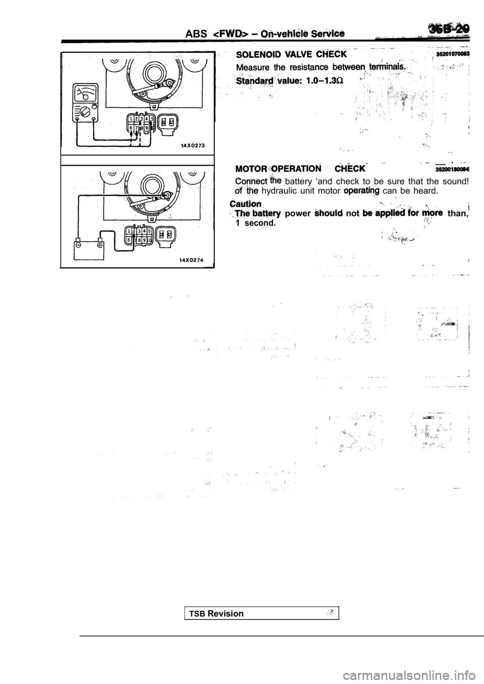
battery ‘and check to be sure that the sound!
hydraulic unit motor can be heard.
power not than,
1 second.
.
TSBRevision
Page 1718 of 2103
ABS On-vehicle Service
Screwdriver
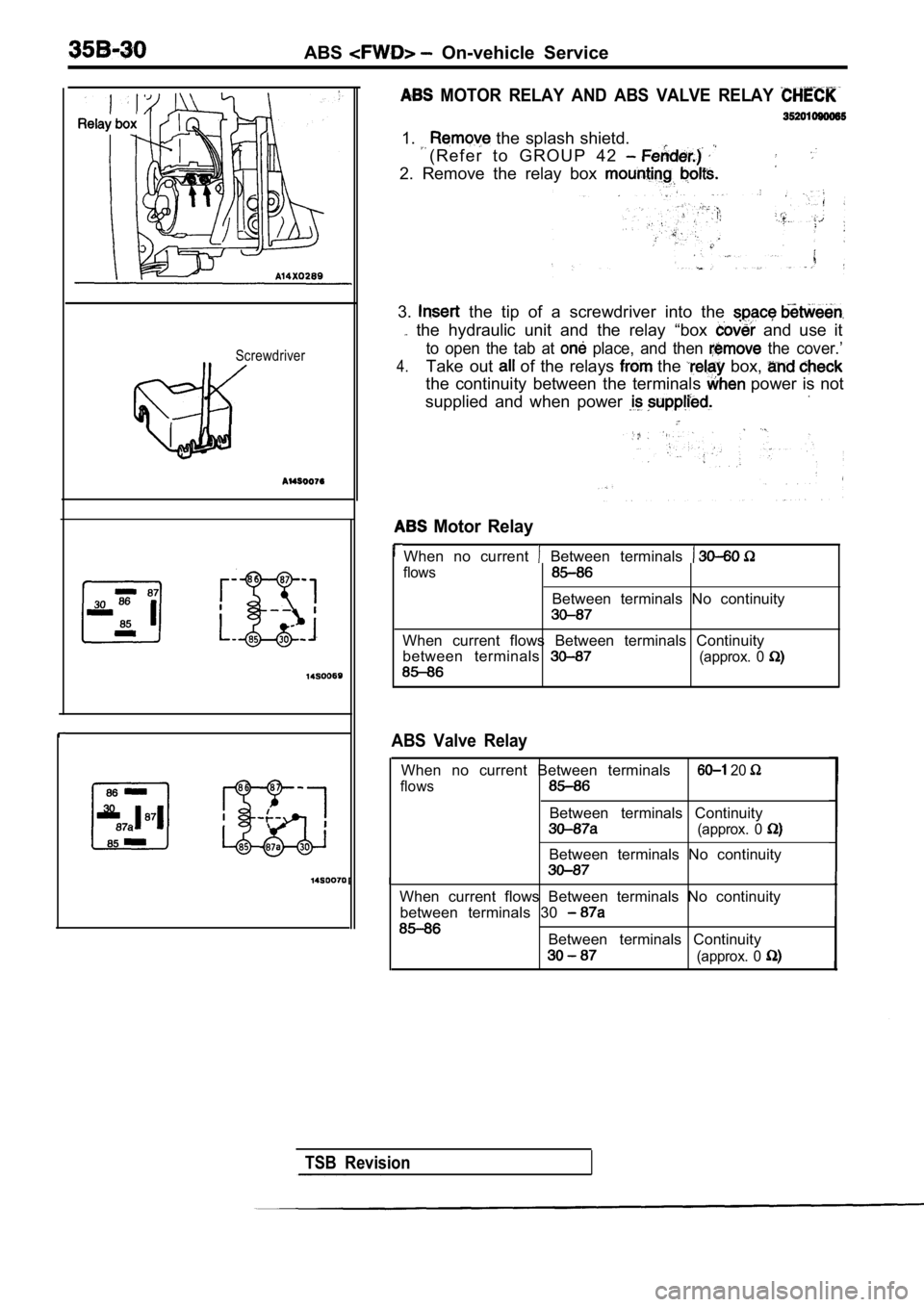
MOTOR RELAY AND ABS VALVE RELAY
1. the splash shietd.
( R e f e r t o G R O U P 4 2
2. Remove the relay box
3. the tip of a screwdriver into the
the hydraulic unit and the relay “box and use it
to open the tab at place, and then the cover.’
4.Take out of the relays the box,
the continuity between the terminals power is not
supplied and when power
Motor Relay
When no current Between terminals
flows
Between terminals No continuity
When current flows Between terminals Continuity
between terminals
(approx. 0
ABS Valve Relay
When no current Between terminals 20
flows
Between terminals Continuity
(approx. 0
Between terminals No continuity
When current flows Between terminals No continuity between terminals 30
Between terminals Continuity
(approx. 0
TSB Revision
Page 1719 of 2103
ABSOn-vehicle Service
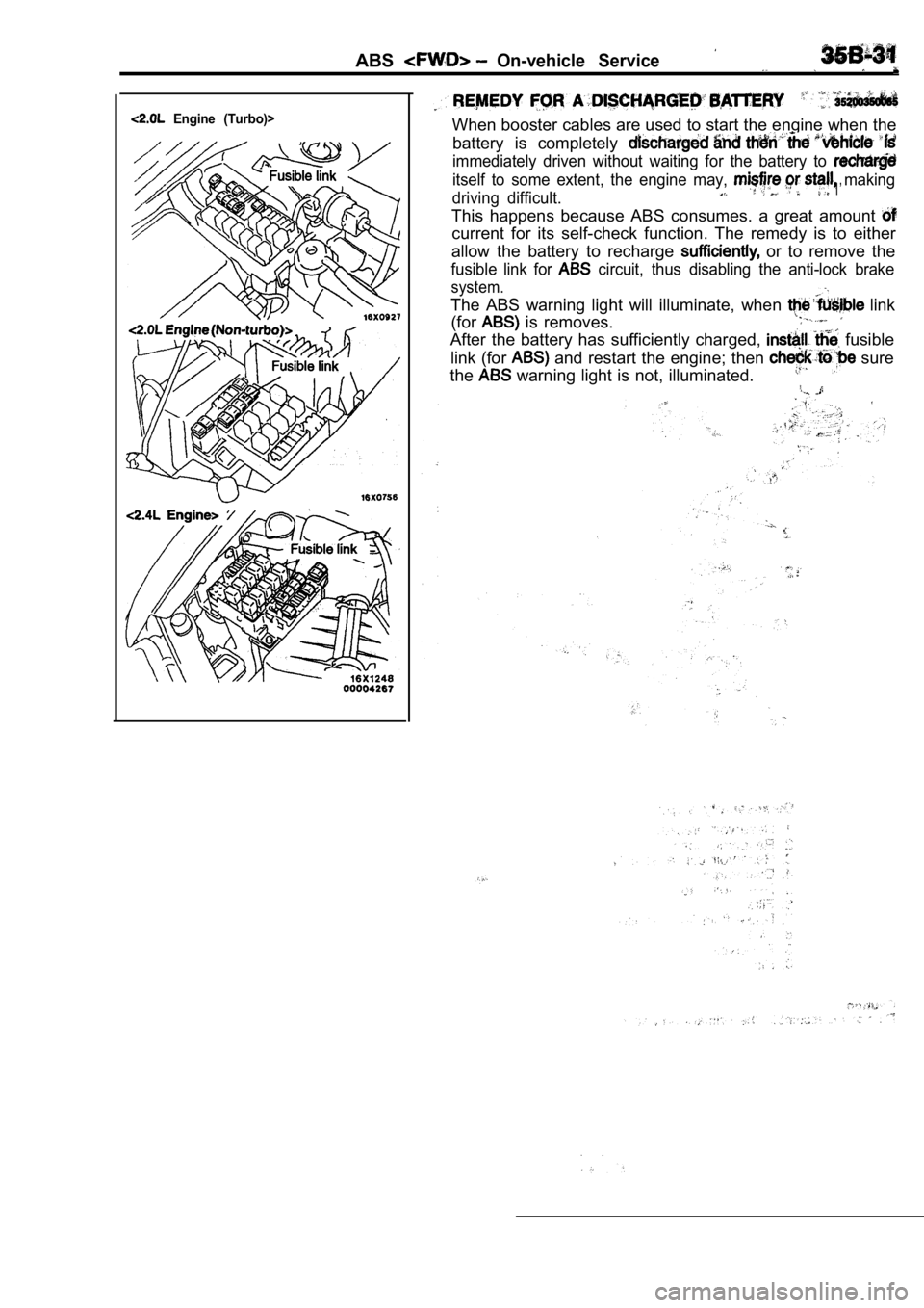
Engine (Turbo)>When booster cables are used to start the engine when the
battery is completely
immediately driven without waiting for the battery to
itself to some extent, the engine may, making
driving difficult. 1’
This happens because ABS consumes. a great amount
current for its self-check function. The remedy is to either
allow the battery to recharge
or to remove the
fusible link for circuit, thus disabling the anti-lock brake
system.
The ABS warning light will illuminate, when link
(for
is removes.
After the battery has sufficiently charged, fusible
link (for
and restart the engine; then sure
the
warning light is not, illuminated.
Page 1720 of 2103
ABS Master Cylinder and Brake Booster
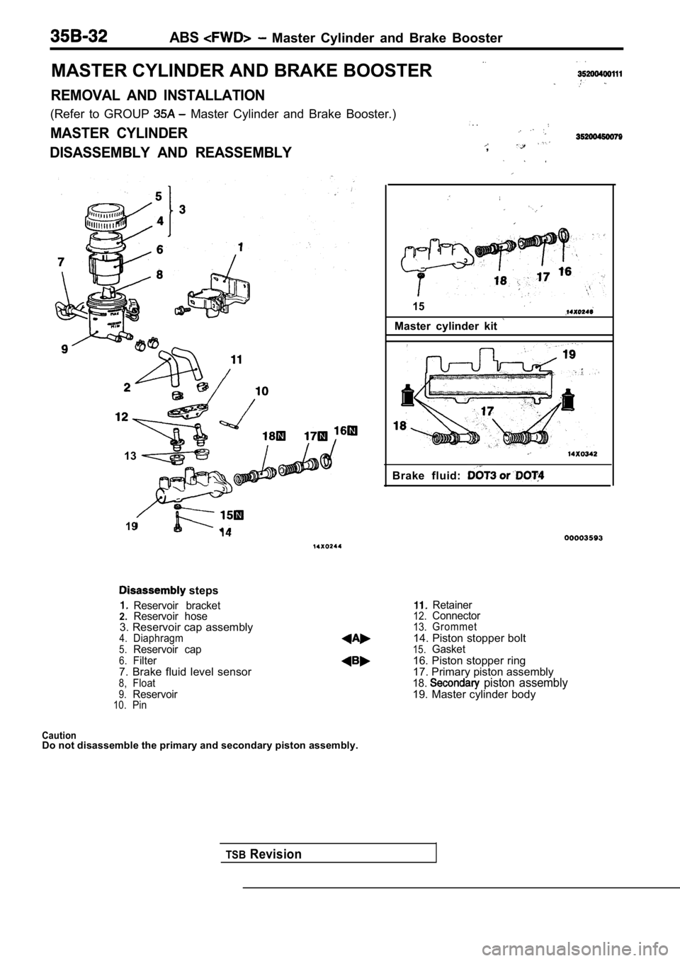
MASTER CYLINDER AND BRAKE BOOSTER
REMOVAL AND INSTALLATION
(Refer to GROUP Master Cylinder and Brake Booster.)
MASTER CYLINDER
DISASSEMBLY AND REASSEMBLY
. .
,
13
TSBRevision
19 14
15
Master cylinder kit
Brake fluid:
steps
Reservoir bracket2.Reservoir hose3. Reservoir cap assembly4.Diaphragm5.Reservoir cap6.Filter7. Brake fluid level sensor8,Float9.Reservoir10.Pin
Retainer12.Connector13.Grommet14. Piston stopper bolt15.Gasket
16. Piston stopper ring
17. Primary piston assembly
18. piston assembly19. Master cylinder body
CautionDo not disassemble the primary and secondary piston
assembly.