MITSUBISHI SPYDER 1990 Service Repair Manual
Manufacturer: MITSUBISHI, Model Year: 1990, Model line: SPYDER, Model: MITSUBISHI SPYDER 1990Pages: 2103, PDF Size: 68.98 MB
Page 1701 of 2103
![MITSUBISHI SPYDER 1990 Service Repair Manual Code No. 51 Valve Probable cause
[Comment] of ABS valve relayWhen the ignition switch is turned ON, the ABS-ECU switches relay OFF Malfunction of harness or and ON for an initial c MITSUBISHI SPYDER 1990 Service Repair Manual Code No. 51 Valve Probable cause
[Comment] of ABS valve relayWhen the ignition switch is turned ON, the ABS-ECU switches relay OFF Malfunction of harness or and ON for an initial c](/img/19/57345/w960_57345-1700.png)
Code No. 51 Valve Probable cause
[Comment] of ABS valve relayWhen the ignition switch is turned ON, the ABS-ECU switches relay OFF Malfunction of harness or and ON for an initial check, compares the voltage of the signal to the valve relay
l Malfunction of hydraulic unit and valve power monitor line voltage to. check whet her the valve relay is
l Malfunction of ABS-ECUnormal.In addition, normally it monitors whether or not th ere is power in the valvepower monitor line since the valve relay is normall y ON.
If the supply of power,to the valve power monitor line is interrupted, thi s diagnostic trouble code will beoutput.
A B S v a l v e r e l a y c h e c k ( R e f e r t oReplace, the ABS valve
Measure at hydraulic unit connector l Disconnect the connector and
lVoltage between terminal 12 and body
Repair
OK N G
Measure at ABS-ECU connector
l Disconnect the connector and mea-
sure at the harness side.
l Resistance value between terminals
OK
) R e p a i r
,
2 27
O K Check trouble symptom.
OK
l Disconnect the connector and
l
. NG Repair
OK
Check trouble symptom. Replace the ABS-ECU.
TSB Revision
Page 1702 of 2103
![MITSUBISHI SPYDER 1990 Service Repair Manual Code No. 53 Motor relay, motor system
[Comment]The ABS-ECU outputs this diagnostic trouble code for the motor relay and motor
in the following cases.
lWhen motor relay is ON MITSUBISHI SPYDER 1990 Service Repair Manual Code No. 53 Motor relay, motor system
[Comment]The ABS-ECU outputs this diagnostic trouble code for the motor relay and motor
in the following cases.
lWhen motor relay is ON](/img/19/57345/w960_57345-1701.png)
Code No. 53 Motor relay, motor system
[Comment]The ABS-ECU outputs this diagnostic trouble code for the motor relay and motor
in the following cases.
lWhen motor relay is ON and no signal is input to th e motor monitor line (when
motor is not operating, etc.)
l
5 seconds or more (when motor continues operating, etc.)
l When the motor relay does not function
ABS motor relay check (Refer to
Inspect the harness between fusible
link No. 8 and the hydraulic unit.
Measure at ABS-ECU connector
l Disconnect the connector and Check the following l
NG,
OK
Check trouble
NG
Check the harness thehydraulic unit and ABS-ECU. Repair,if
l Disconnect the connector and
Revision
.
Repair.
OK
Check trouble symptom.NG Replace the ABS-ECU.
Page 1703 of 2103

ABS Troubleshooting
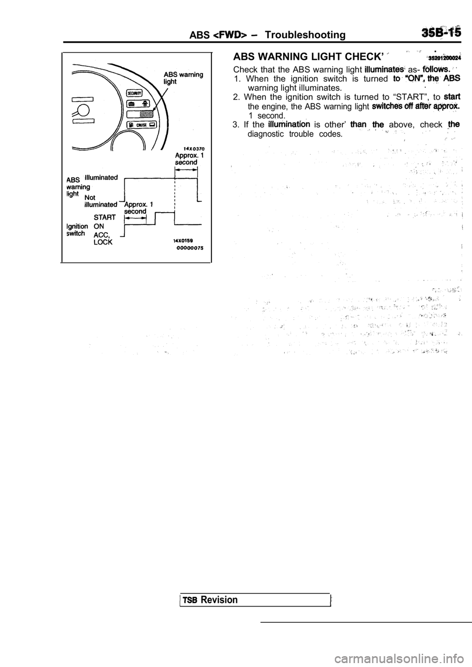
ABS WARNING LIGHT CHECK’
.
Check that the ABS warning light as-
1. When the ignition switch is turned
warning light illuminates..
2. When the ignition switch is turned to “START”, t
o
the engine, the ABS warning light
1 second.
3. If the is other’ above, check
diagnostic trouble codes.
Revision
Page 1704 of 2103

6ABS
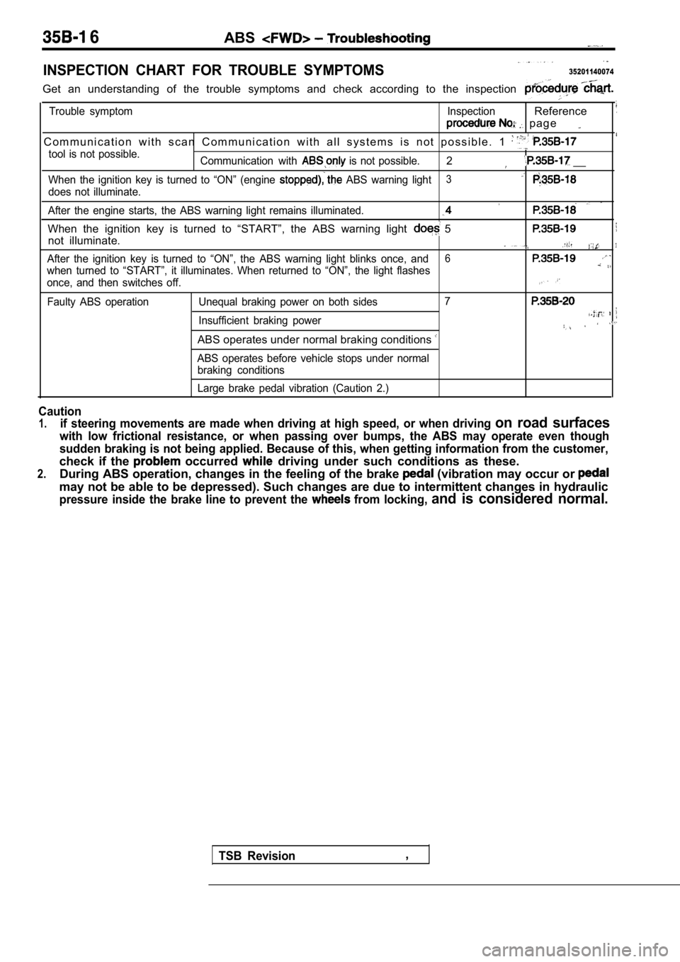
INSPECTION CHART FOR TROUBLE SYMPTOMS35201140074
Get an understanding of the trouble symptoms and check according to the inspection
Trouble symptom InspectionReference
p a g e
C o m m u n i c a t i o n w i t h s c a n C o m m u n i c a t i o n w i t h a l l s y s te m s i s n o t p o s s i b l e . 1
tool is not possible.
Communication with is not possible.2 __
When the ignition key is turned to “ON” (engine ABS warning light3
does not illuminate.
After the engine starts, the ABS warning light rema ins illuminated.
When the ignition key is turned to “START”, the ABS warning light 5
not illuminate.
After the ignition key is turned to “ON”, the ABS warning light blinks once, and6
when turned to “START”, it illuminates. When return ed to “ON”, the light flashes
once, and then switches off.
Faulty ABS operation Unequal braking power on both s ides7
Insufficient braking power
ABS operates under normal braking conditions
ABS operates before vehicle stops under normal
braking conditions
Large brake pedal vibration (Caution 2.)
Caution
1.if steering movements are made when driving at high speed, or when driving on road surfaces
with low frictional resistance, or when passing over bumps, the ABS may operate even though
sudden braking is not being applied. Because of thi s, when getting information from the customer,
check if the occurred driving under such conditions as these.
2.During ABS operation, changes in the feeling of the brake (vibration may occur or
may not be able to be depressed). Such changes are due to intermittent changes in hydraulic
pressure inside the brake line to prevent the from locking, and is considered normal.
TSB Revision,
Page 1705 of 2103
![MITSUBISHI SPYDER 1990 Service Repair Manual INSPECTION PROCEDURE FOR TROUBLE SYMPTOMS .
INSPECTION PROCEDURE , .,, , __ ,
Communication with scan not possible. , .
(Communication with all is not Probablecause
[Comment]Th MITSUBISHI SPYDER 1990 Service Repair Manual INSPECTION PROCEDURE FOR TROUBLE SYMPTOMS .
INSPECTION PROCEDURE , .,, , __ ,
Communication with scan not possible. , .
(Communication with all is not Probablecause
[Comment]Th](/img/19/57345/w960_57345-1704.png)
INSPECTION PROCEDURE FOR TROUBLE SYMPTOMS .
INSPECTION PROCEDURE , .,, , __ ,
Communication with scan not possible. , .
(Communication with all is not Probablecause
[Comment]The reason is probably a defect in supply system (including ground) forl .
the diagnostic line.. . . .
Refer to GROUP -Troubleshooting.
.I N S P E C T I O N P R O C E D U R E 2
(Communication with ABS only is not
Communication with scan tool is ,
l Blown fuseWhen the s&an tool is not possible, the cause is probab ly anopen circuit in the ABS-ECU power circuit or an ope n circuit in the diagnostic outputl Malfunction of connector
l Malfunction of ABS-ECU
circuit.. . . .
NGMeasure at data link connector Repairand ABS-ECU connector -1.lDisconnect the connector and mea-sure at the side.
Continuity between the following
terminals.OK: Continuity
ABS-ECU side to Data link
connector side C h e c k t h e between the
ABS-ECU and link connector. . . necessary.
OK.NG NGMeasure at ABS-ECU connector RepairlDisconnect the connector and mea-* and sure at the harness side.
l Ignition switch ONOK
l Voltage between terminal 18 and ground. Check trouble symptomsOK: Battery positive voltage
OKCheck the harness between fuse No.
.13 the junction block andABS-ECU. Repair, if necessary. .
Measure at ABS-ECU connector . . lDisconnect the connector and mea-sure at the harness side.l and body ground..OK: Continuity
TSB Revision
Page 1706 of 2103
![MITSUBISHI SPYDER 1990 Service Repair Manual ABS Troubleshooting , ,
INSPECTION PROCEDURE 3When ignition key is turned to “ON” (engine stopped ),
ABS warning light does not illuminate
[Comment]When power is supplied to the MITSUBISHI SPYDER 1990 Service Repair Manual ABS Troubleshooting , ,
INSPECTION PROCEDURE 3When ignition key is turned to “ON” (engine stopped ),
ABS warning light does not illuminate
[Comment]When power is supplied to the](/img/19/57345/w960_57345-1705.png)
ABS Troubleshooting , ,
INSPECTION PROCEDURE 3When ignition key is turned to “ON” (engine stopped ),
ABS warning light does not illuminate
[Comment]When power is supplied to the ABS-ECU, the valve relay changes from to ON by the initial check, and thus even if there is a problem with the circuit between
ABS light and ABS-ECU, the light will illuminate once when the valve relay
is OFF.
Accordingly, the cause of the light not illuminatin g is probably an open circuit in the
light power circuit, a blown light bulb, or an open circuit in both the circuit between
the ABS
light and the ABS-ECU and the circuit between the ABS light and the ABS valve relay.When other lights also do not illuminate, the cause is probably a blown fuse.
Measure at combination meter connector
l Disconnect the connector and mea-
sure at the harness side.
l Ignition Switch ON
lVoltage between terminal 10 and body
OK Battery positive voltage Check trouble symptoms
Measure at combination meter connector
sure at the combination meter side.
l Continuitv between terminals
R e p l a c e t h e
OK Continuity ,
OK
Check the harnesses between the ABS valve relay and the combination meter,
a n d b e t w e e n t h e A B S - E C U a n d
combination meter (common section).
if necessary.
INSPECTION PROCEDURE 4
TSB Revision.
Even after the engine is started, the ABS Warning l ight ,remains illuminated.. .
[Comment]There is probably a short in the ABS warning light illumination circuit.l Malfunction of combination meterl Malfunction of ABS valve relayl Malfunction of ABS-ECU. ,
NOTE
This trouble symptom is limited to cases where comm unication with the scan tool is’
is normal) and the diagnostic trouble code is a normal diagnostic trouble code..YESDisconnect the ABS-ECU connector Does the light remain illuminated?
NO
Short circuit inside the combination or in the harnessbetween the meter and
Replace the ABS-ECU.
Page 1707 of 2103
![MITSUBISHI SPYDER 1990 Service Repair Manual When ignition key is turned ABS warning lightProbable.
does not illuminate.
[Comment]The ABS-ECU uses the the which is cut when the ignition switch is’l o f
turned to “START� MITSUBISHI SPYDER 1990 Service Repair Manual When ignition key is turned ABS warning lightProbable.
does not illuminate.
[Comment]The ABS-ECU uses the the which is cut when the ignition switch is’l o f
turned to “START�](/img/19/57345/w960_57345-1706.png)
When ignition key is turned ABS warning lightProbable.
does not illuminate.
[Comment]The ABS-ECU uses the the which is cut when the ignition switch is’l o f
turned to “START”. The ABS light uses power which is not cut even
l when the ignition switch is turned to “START”.Accordingly, because the power to the ABS-ECU is st
opped in “START” position,
if the light does not illuminate at this time, the cause is a problem in the __ light illumination circuit in the valve relay.
N GMeasure at hydraulic unit connector NG_..l Disconnect the connector and mea- Repair
sure at the harness side.lVoltaae between terminal and bodv
v o l t a g e trouble symptom.
Replace the hydraulic unit.
INSPECTION PROCEDURE 6
The ABS warning light flashes once after the igniti on key
Probable cause
is turned to “ON”. The light
when
is turned to “START”, and when the is to
it flashes once.I[Comment]l Malfunction of wiring harness or When power flows, the ABS-ECU turns on the warning light for approximately secondl Malfunction of ABS-ECU
while it performs a valve relay test. If there is a break in the harness between the
ECU and the
light illuminates only when the valve relay is off in valve
relay test, etc.
NGMeasure at ABS-ECU connector Check the connectors:
l Disconnect the connector and mea- a n d Repair
sure at the harness side.
combination meter and the ABS-ECU.Repair, if
.
,
Repair
OK
Check trouble symptom. Replace the ABS-ECU.
TSB RevisionI
Page 1708 of 2103
![MITSUBISHI SPYDER 1990 Service Repair Manual ABS Troubfeshooting , .
INSPECTION PROCEDURE 7
Break operation is abnormal
[Comment]This varies depending on the driving conditions and the road surface conditions, soproblem diagnosis is d MITSUBISHI SPYDER 1990 Service Repair Manual ABS Troubfeshooting , .
INSPECTION PROCEDURE 7
Break operation is abnormal
[Comment]This varies depending on the driving conditions and the road surface conditions, soproblem diagnosis is d](/img/19/57345/w960_57345-1707.png)
ABS Troubfeshooting , .
INSPECTION PROCEDURE 7
Break operation is abnormal
[Comment]This varies depending on the driving conditions and the road surface conditions, soproblem diagnosis is difficult. However, if a normal diagnostic trouble code is displayed,carry out the following
l Malfunction of wheel speed l Malfunction of ABS rotor
l Malfunction of wheel bearing
of hydraulic Malfunction of ABS-ECU
NG Repair
(Refer to
Wheel speed sensor output voltage check [ R e p l a c e t h e w h e e l
Hydraulic unit check (Refer to 1NGABS rotor check (Refer to Replace the rotor.
O K NGWheel bearing end play check Refer to GROUP 26 On-vehicle Repair
Service.Refer to GROUP 27 On-vehicleIService.I
Check trouble symptom.
ABS-ECU connector l Disconnect the connector and
measure at the harness side.
l Resistance vaiue between termi-
nals
14-15, and
O KThe sensor harness and connector
should be moved while these checks
are carded out.
OK
Repair
TSB Revision
Repair
.
NG Repair
OK
Check trouble symptom.N G Replace ABS-ECU.
Page 1709 of 2103

ABS
Needle-nosed wire probe .I
I
Connector terminal. arrangement for
troubleshooting
Terminal arrangement shown on the
special tool connector
0 0 0 0 0 0 7 8
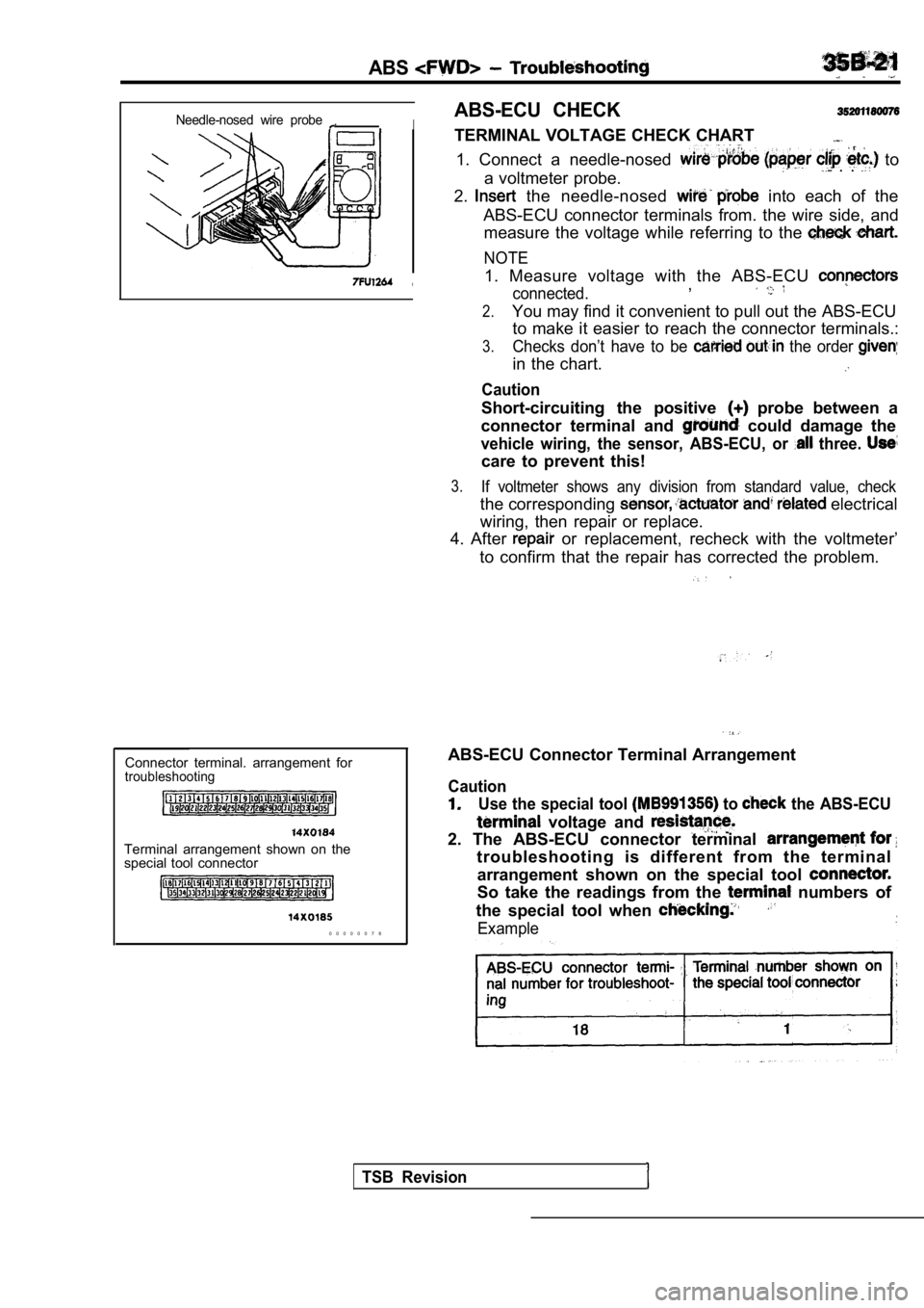
ABS-ECU CHECK
TERMINAL VOLTAGE CHECK CHART
1. Connect a needle-nosed to
a voltmeter probe. . .
2. the needle-nosed into each of the
ABS-ECU connector terminals from. the wire side, an d
measure the voltage while referring to the
NOTE
1. Measure voltage with the ABS-ECU
connected.,
2.You may find it convenient to pull out the ABS-ECU to make it easier to reach the connector terminals. :
3.Checks don’t have to be the order
in the chart.
Caution
Short-circuiting the positive probe between a
connector terminal and
could damage the
vehicle wiring, the sensor, ABS-ECU, or three.
care to prevent this!
3.If voltmeter shows any division from standard value , check
the corresponding electrical
wiring, then repair or replace.
4. After
or replacement, recheck with the voltmeter’
to confirm that the repair has corrected the proble m.
ABS-ECU Connector Terminal Arrangement
Caution
Use the special tool to the ABS-ECU
voltage and
2. The ABS-ECU connector terminal
troubleshooting is different from the terminal
arrangement shown on the special tool
So take the readings from the numbers of
the special tool when
Example
TSB Revision
Page 1710 of 2103

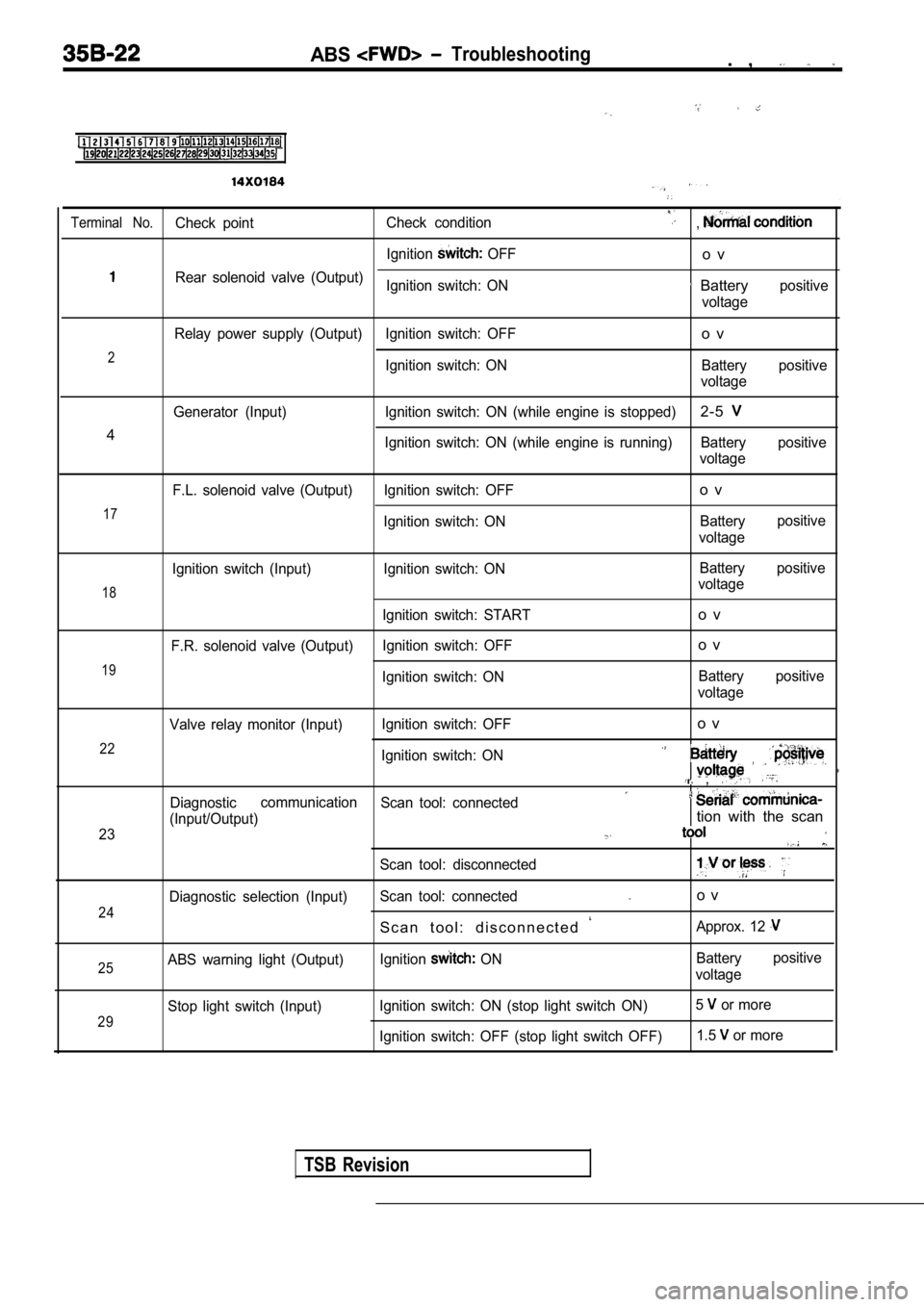
ABS Troubleshooting. ,
Terminal No.Check pointCheck condition,
Ignition OFFo v
Rear solenoid valve (Output)
Ignition switch: ON Batterypositive
voltage
Relay power supply (Output) Ignition switch: OFF
o v
2Ignition switch: ON Battery positive voltage
Generator (Input) Ignition switch: ON (while engine is stopped)
2-5
4Ignition switch: ON (while engine is running) Battery positive
voltage
17
F.L. solenoid valve (Output) Ignition switch: OFF
Ignition switch: ONo v
Batterypositive
voltage
18
19
Ignition switch (Input)
F.R. solenoid valve (Output) Ignition switch: ON
Ignition switch: START
Ignition switch: OFF
Ignition switch: ON Battery
voltage
o v
o v
Battery
voltage positive
positive
22
23 Valve relay monitor (Input)
Ignition switch: OFF
o v
Ignition switch: ON
,
Diagnosticcommunication
Scan tool: connected
(Input/Output)tion with the scan
24
Diagnostic selection (Input) Scan tool: disconnectedScan tool: connectedo v
S c a n t o o l : d i s c o n n e c t e d
Approx. 12
25ABS warning light (Output) Ignition ON Battery
voltage positive
29
Stop light switch (Input)
Ignition switch: ON (stop light switch ON) 5 or more
Ignition switch: OFF (stop light switch OFF) 1.5
or more
TSB Revision