torque MITSUBISHI SPYDER 1990 Service Repair Manual
[x] Cancel search | Manufacturer: MITSUBISHI, Model Year: 1990, Model line: SPYDER, Model: MITSUBISHI SPYDER 1990Pages: 2103, PDF Size: 68.98 MB
Page 1787 of 2103
S T E E R I N G
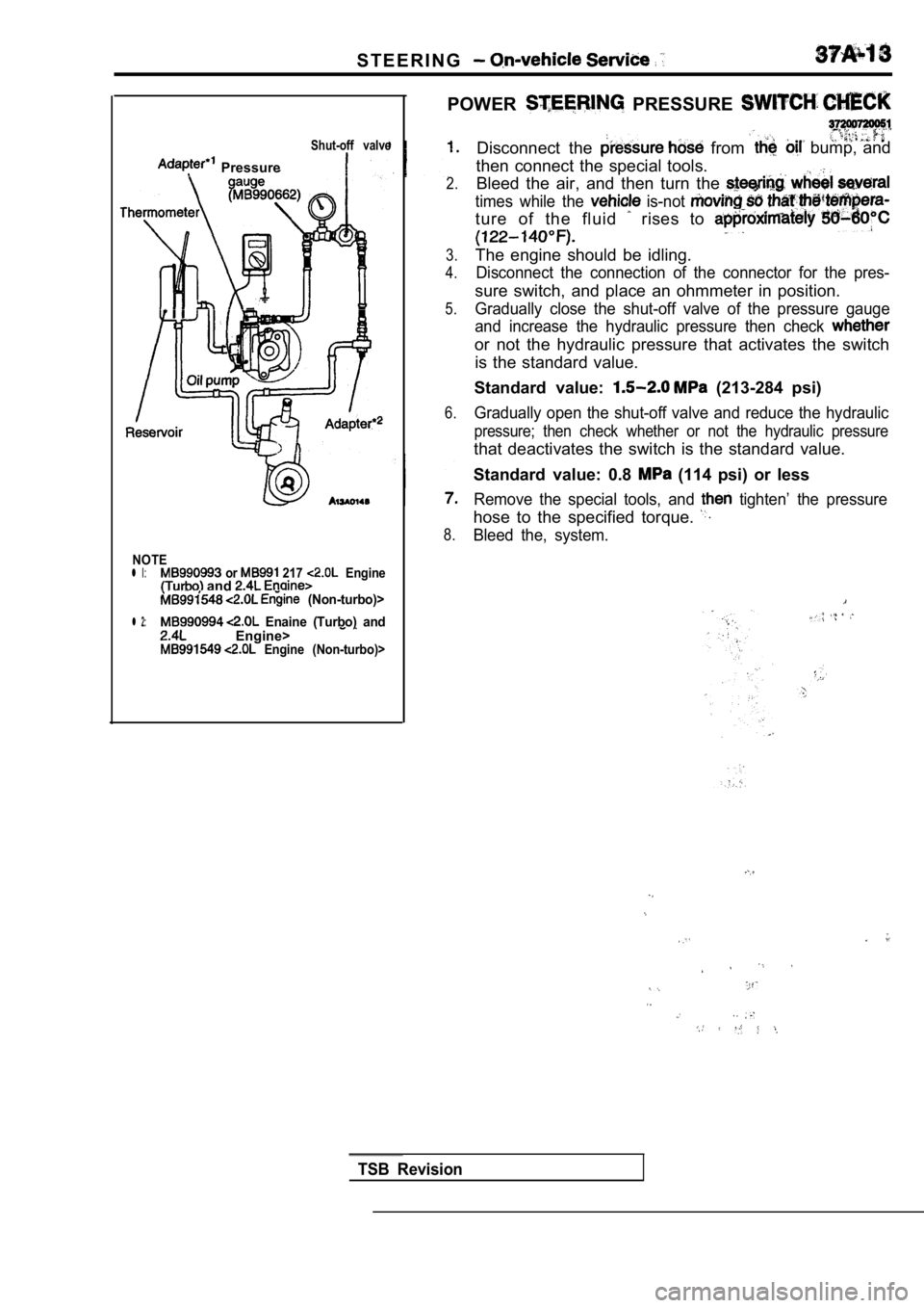
POWER PRESSURE
Shut-off valve
Pressure
2.
3.
4.
Disconnect the from bump, and
then connect the special tools. Bleed the air, and then turn the
times while the is-not
ture of the fluid rises to
The engine should be idling.
5.
Disconnect the connection of the connector for the pres-
sure switch, and place an ohmmeter in position.
Gradually close the shut-off valve of the pressure gauge
and increase the hydraulic pressure then check
or not the hydraulic pressure that activates the sw itch
is the standard value.
Standard value:
(213-284 psi)
6.Gradually open the shut-off valve and reduce the hy draulic
pressure; then check whether or not the hydraulic p ressure
that deactivates the switch is the standard value.
Standard value: 0.8
(114 psi) or less
8.
Remove the special tools, and tighten’ the pressure
hose to the specified torque.
Bleed the, system.
NOTEl l or 217 Engine and (Non-turbo)>
l 2: Enaine (Turbo) and Engine> Engine (Non-turbo)>
TSB Revision
Page 1796 of 2103
S T E E R I N G
TSB Revision
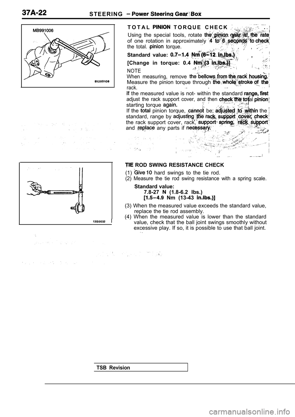
T O T A L T O R Q U E C H E C K .
Using the special tools, rotate
of one rotation in approximately
the total. torque. , ,
Standard value: ,
[Change in torque: 0.4
NOTE.
When measuring, remove
Measure the pinion torque through
rack. .
the measured value is not- within the standard
adjust the rack support cover, and then
starting torque
al
If the pinion torque, be; the
standard, range by
the rack support cover, rack,
and any parts if
ROD SWING RESISTANCE CHECK
(1)
hard swings to the tie rod.
(2) Measure the tie rod swing resistance with a spr ing scale.
Standard value:
7.8-27
(1.8-6.2 Ibs.)
Nm (13-43
(3) When the measured value exceeds the standard va lue,
replace the tie rod assembly.
(4) When the measured value is lower than the stand ard
value, check that the ball joint swings smoothly wi thout
excessive play. If so, it is possible to use that b all joint.
.
Page 1797 of 2103
Power Steering Gear
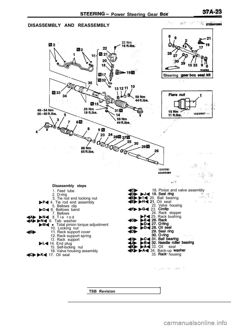
DISASSEMBLY AND REASSEMBLY
6
22 Nm
Steering
Disassembly steps
1.Feed tube2.O-ring3. Tie rod end locking nut
4. Tie rod end assembly5.Bellows clip 6. Bellows band7.Bellows8.T i e r o d 9. Tab washer l Total pinion torque adjustment
10. Locking nut
11. Rack support cover
12. Rack support spring
13.Rack support
14. End plug15.Self-locking nut16. Valve housing assembly
17. Oil seal 18. Pinion and valve assembly
20. Bali bearing 21.
Oil seal22.Valve housing
23. 24. Rack stopper 25. Rack bushing
33.Oil seal
34. Back-up 35. housing
TSB Revision
Page 1804 of 2103
STEERING Power Steering Gear Box
Bellows band
Concave
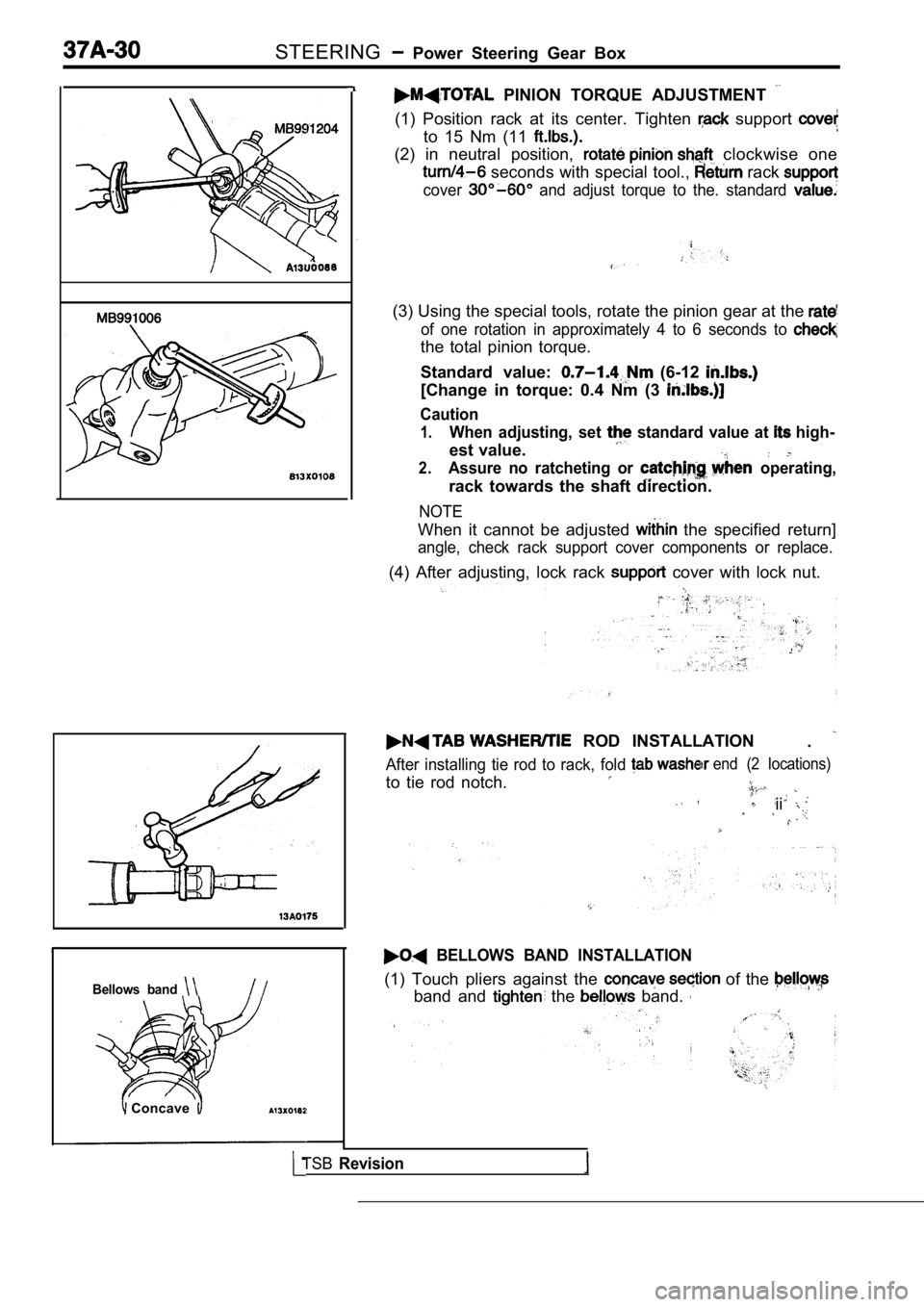
PINION TORQUE ADJUSTMENT
(1) Position rack at its center. Tighten support
to 15 Nm (11
(2) in neutral position, clockwise one
seconds with special tool., rack
cover and adjust torque to the. standard
(3) Using the special tools, rotate the pinion gear at the
of one rotation in approximately 4 to 6 seconds to
the total pinion torque.
Standard value:
(6-12
[Change in torque: 0.4 Nm (3
Caution
1.When adjusting, set standard value at high-
est value.
2.Assure no ratcheting or operating,
rack towards the shaft direction.
NOTE
When it cannot be adjusted the specified return]
angle, check rack support cover components or repla ce.
(4) After adjusting, lock rack cover with lock nut.
ROD INSTALLATION
.
After installing tie rod to rack, fold
to tie rod notch.
end (2 locations)
ii
BELLOWS BAND INSTALLATION
(1) Touch pliers against the of the
band and the band.
TSBRevision
Page 1838 of 2103
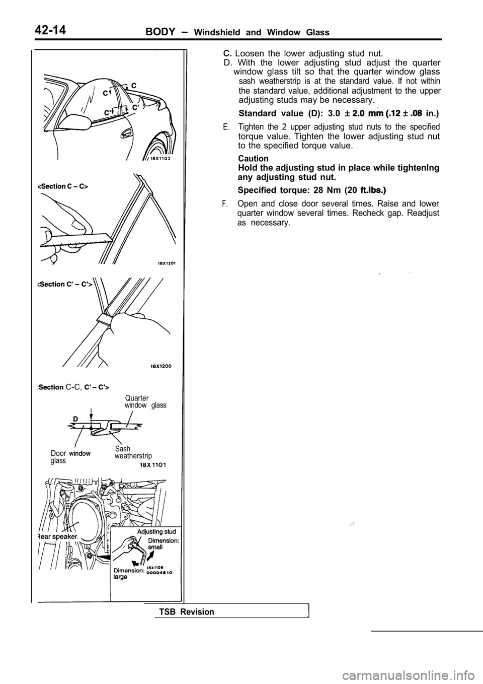
42-14BODY Windshield and Window Glass
C-C,
Quarter
window glass
Doorglass Sash
weatherstrip
Loosen the lower adjusting stud nut.
D. With the lower adjusting stud adjust the quarter window glass tilt so that the quarter window glass
sash weatherstrip is at the standard value. If not within
the standard value, additional adjustment to the upper
adjusting studs may be necessary.
Standard value (D): 3.0
in.)
E.Tighten the 2 upper adjusting stud nuts to the spec ified
torque value. Tighten the lower adjusting stud nut
to the specified torque value.
Caution
Hold the adjusting stud in place while tightenlng
any adjusting stud nut.
Specified torque: 28 Nm (20
F.Open and close door several times. Raise and lower
quarter window several times. Recheck gap. Readjust
as necessary.
TSB Revision
Page 1976 of 2103
INTERIOR Front Seat
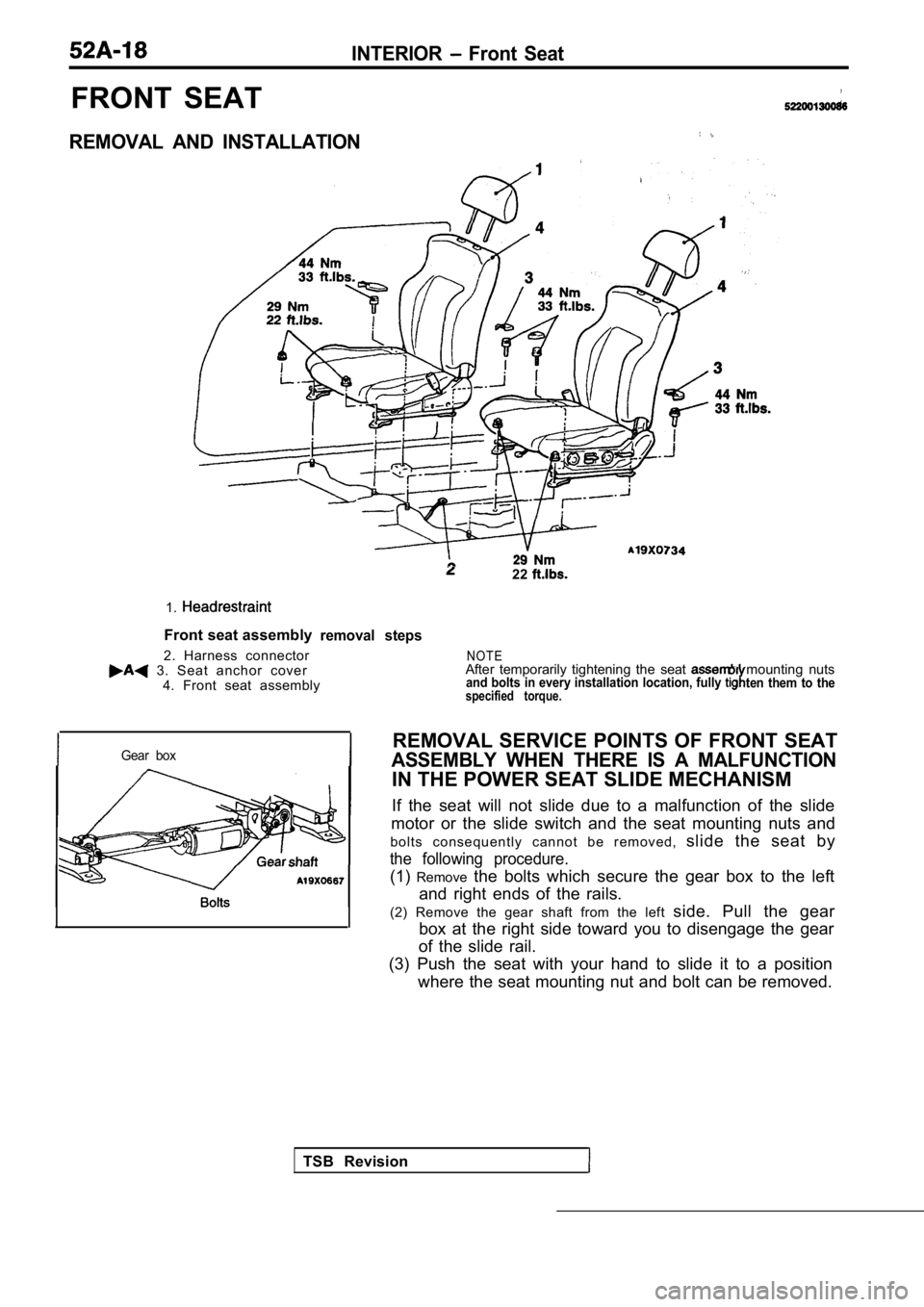
FRONT SEAT
REMOVAL AND INSTALLATION
1.
Front seat assembly
2. Harness connector
3. Seat anchor cover 4. Front seat assembly
22
removal steps
Gear box
TSB Revision
N O T EAfter temporarily tightening the seat mounting nutsand bolts in every installation location, fully ten them to thespecified torque.
REMOVAL SERVICE POINTS OF FRONT SEAT
ASSEMBLY WHEN THERE IS A MALFUNCTION
IN THE POWER SEAT SLIDE MECHANISM
If the seat will not slide due to a malfunction of the slide
motor or the slide switch and the seat mounting nut s and
b o l t s c o n s e q u e n t l y c a n n o t b e r e m o v e d , slide the seat by
the following procedure.
(1)Remove the bolts which secure the gear box to the left
and right ends of the rails.
(2) Remove the gear shaft from the left side. Pull the gear
box at the right side toward you to disengage the g ear
of the slide rail.
(3) Push the seat with your hand to slide it to a p osition
where the seat mounting nut and bolt can be removed .
Page 2056 of 2103
6HEATER, AIR
AND VENTILATION On-vehicle Service
COMPRESSOR NOISE CHECK
You must first know the conditions when the noise occurs. These conditions are: weather, vehicle speed,
in gear or neutral, engine temperature or any other special conditions.
Noises that develop during A/C operation can often be misleading. For example: what sounds like a
failed front bearing or connecting rod, may be caus ed by loose bolts, nuts, mounting brackets, or a
loose clutch assembly. Verify accessory drive belt tension (power steering or generator).
Improper accessory drive belt tension can cause a m isleading noise when the compressor is engaged
and little or no noise when the compressor is disen gaged.
Drive belts are speed-sensitive. That is, at differ ent engine speeds, and depending upon belt tension,
belts can develop unusual noises that are often mis taken for mechanical problems within the compressor .
ADJUSTMENT
1. Select a quiet area for testing. Duplicate conditions as much as possible. Switch compressor on
and off several times to clearly identify compresso r noise. To duplicate high ambient
head pressure), restrict air flow through condenser . Install manifold gauge set sure discharge
pressure doesn’t exceed 2,070 (300 psi).
2. Tighten all compressor mounting bolts, clutch mo unting bolt, and compressor drive belt. Check to
assure clutch coil is tight (no rotation or wobble) .
3. Check refrigerant hoses for rubbing or interfere nce that can cause unusual noises.
4. Check refrigerant charge. (Refer to
5. Recheck compressor noise as in Step 1.
6. If noise still exists, loosen compressor mountin g bolts and retorque. Repeat Step 1.
7. If noise continues, replace compressor and repea t Step 1.
Revision
Page 2081 of 2103
![MITSUBISHI SPYDER 1990 Service Repair Manual and Tension
Engine (Non-turbo)>
Bolt mm in.)]
Socket
Deep socket
(14 mm
in.)]
TSB
HUB REMOVAL
(1) Remove the clutch hub mounting bolt.
(2) Tighten a
mm in.) bolt into the ho MITSUBISHI SPYDER 1990 Service Repair Manual and Tension
Engine (Non-turbo)>
Bolt mm in.)]
Socket
Deep socket
(14 mm
in.)]
TSB
HUB REMOVAL
(1) Remove the clutch hub mounting bolt.
(2) Tighten a
mm in.) bolt into the ho](/img/19/57345/w960_57345-2080.png)
and Tension
Engine (Non-turbo)>
Bolt mm in.)]
Socket
Deep socket
(14 mm
in.)]
TSB
HUB REMOVAL
(1) Remove the clutch hub mounting bolt.
(2) Tighten a
mm in.) bolt into the hole of the
clutch hub to remove the serration assembly the shaft
and the clutch hub.
SEAL INSTALLATION
Use a 21 mm in.) socket to install the shaft seal so
that the O-ring assembly side is facing the front h ousing.
FELT, FELT HOLDER INSTALLATION
After installing the felt in the felt holder, them to the
front housing using a 14 mm
deep socket.
FRONT HOUSING INSTALLATION
(1) Apply compressor oil to the shaft.
Compressor oil: ND-OIL 8
(2) Install the front housing without damaging the shaft seal
lip.
(3) After installing the front housing, install the clutch hub
mounting bolt to the shaft, and check that the breakaway
torque is within the torque value.
Breakaway torque:
Nm (4 or less
Page 2093 of 2103
ALPHABETICAL
A
ABS OPERATIONCheck. . . . . . . . . . . . . . . . . . . . . . . . . . . . . . . . . . .
. . . . . . . . . . . . . . . . . . . . . . . . . . . . . . . . . . .
ABS-ECU. . . . . . . . . . . . . . . . . . . . . . . . . . . . . . . . . . . . . . . . .
. . . . . . . . . . . . . . . . . . . . . . . . . . . . . . . . . . . . . . . . .
ACCELERATOR CABLE. . . . . . . . . . . . . . . . . . . . . . . . . . . . . . . .Adjustment. . . . . . . . . . . . . . . . . . . . . . . . . . . . . . . . . . . . . . . . .
Check. . . . . . . . . . . . . . . . . . . . . . . . . . . . . . . . . . . . . . . . . . . . .ACCELERATOR PEDAL. . . . . . . . . . . . . . . . . . . . . . . . . . . . . . . .
ADAPTER, Transfer Case . . . . . . . . . . . . . . . . . .
AERO PARTS. . . . . . . . . . . . . . . . . . . . . . . . . . . . . . . . . . . . . . . .
AIR BAG CONTROL UNIT (SRS-ECU), SRS. . . . . . . . . . .AIR BAG MODULES. . . . . . . . . . . . . . . . . . . . . . . . . . . . . . . . .
Deployed Disposal Procedures. . . . . . . . . . . . . . . . . . . . .
Disposal Procedures. . . . . . . . . . . . . . . . . . . . . . . . . . . . .
Disposal. . . . . . . . . . . . . . . . . . . . . . . . . . . . .
AIR CLEANER ELEMENT, Maintenance. . . . . . . . . . . . . . . . . .AIR CONDITIONING SWITCH
ENGINE (NON-TURBO)>. . . . . . . . . . . . . . ENGINE (TURBO) AND .AIR COOLER, charge. . . . . . . . . . . . . . . . . . . . . . . . . . . . . . . . . . .
AIR FILTER. . . . . . . . . . . . . . . . . . . . . . . . . . . . . . . . . . . . . . . . . .
ALIGNMENT
Front Wheel, Check and Adjustment. . . . . . . . . . . . . . . . .
Wheel, Rear, Check and Adjustment. . . . . . . . . . . . . . . . . . .AMPLIFIER. . . . . . . . . . . . . . . . . . . . . . . . . . . . . . . . . . . . . . . . . .
GEAR AND TRANSFER DRIVE GEAR SET
. . . . . . . . . . . . . . . . . . . . . . . . . . . . . . . .
. . . . . . . . . . . . . . . . . . . . . . . . . . . . . . . . . . . . . . . .
ANTENNA.
ARM Compression, Lower
. . . . . . . . . . . . . . . . . . . . . . . . . . . . . . .Lateral, Lower. . . . . . . . . . . . . . . . . . . . . . . . . . . . . . . . . . .
Lower. . . . . . . . . . . . . . . . . . . . . . . . . . . . . . . . . . . . . . . . . . . . .
Toe Control. . . . . . . . . . . . . . . . . . . . . . . . . . . . . . . . . . . . . . . .
Trailing. . . . . . . . . . . . . . . . . . . . . . . . . . . . . . . . . . . . . . . . . . . .
Upper
Suspension>. . . . . . . . . . . . . . . . . . . . . . . . . . .ARMS, Rocker . . . . . . . . . . . . . . . . . . . . . . . . . . .11AUTO-CRUISE CONTROL. . . . . . . . . . . . . . . . . . . . . . . . . . . . .
AUTO-CRUISE CONTROL CABLE, Check andAdjustment. . . . . . . . . . . . . . . . . . . . . . . . . . . . . . . . . . . . . . . . . . .
AUTO-CRUISE CONTROL COMPONENT, Check. . . . . . . . .AUTO-CRUISE CONTROL SYSTEM, Operation Check. . . .AUTOMATIC TRANSAXLE FLUID, Maintenance. . . . . . . . . .AUTOMATIC TRANSAXLE CONTROL COMPONENTCheck
ENGINE (NON-TURBO)>.. . . . . . . . . . . .Layout ENGINE (NON-TURBO)>. . . . . . . . . . . .AUTOMATIC TRANSAXLE KEY INTERLOCK AND SHIFT LOCKMECHANISMS
ENGINE (NON-TURBO)>. . . . . . . . . . . . . . . . . . .
ENGINE (TURBO) AND ENGINE>.. . . . . . .AXLE
Rear, Total Backlash Check. . . . . . . . . . . . . . . . . . . . . . . . . .
AXLE OIL
Rear, Maintenance
. . . . . . . . . . . . . . . . . . . . . . . . . . . . . . . . .
BACK-UP LIGHT. . . . . . . . . . . . . . . . . . . . . . . . . . . . . . . . . . . . .BALL JOINT, Tie Rod End, Breakaway Torque Check. . . . .BALL JOINT SEALS, Maintenance. . . . . . . . . . . . . . . . . . . . . .
BARStabilizer Suspension>. . . . . . . . . . . . . . . . . . . . .
Suspension>. . . . . . . . . . . . . . . . . . . . . . . .
BASIC IDLE SPEED, Adjustment ENGINE (TURBO)
AND ENGINE>. . . . . . . . . . . . . . . . . . . . . . . . . . . . . . . .
BATTERY
Charging
. . . . . . . . . . . . . . . . . . . . . . . . . . . . . . . . . . . . . . . . . .
Check. . . . . . . . . . . . . . . . . . . . . . . . . . . . . . . . . . . . . . . . . . ..Testing Procedure. . . . . . . . . . . . . . . . . . . . . . . . . . . . .. . .
BELT
Compressor, Adjustment. . . . . . . . . . . . . . . . . . . . . . . . .
(For Generator), Maintenance. . . . . . . . . . . .. . . . . (For Power steering pump), Maintenance. . . . . . . . . (For Water pump), Maintenance. . . . . . . . .. .. . .Timing. . . . . . . . . . . . . . . . . . . .
. . . . . . . . . . . . . . . . . . . . . . . . . . .
Timing. . . . . . . . . . . . . . . . . . . . . . . . . . . . .
. . . . . . . . . . . . . . . . . . . . . ... . . . . . . . .
. . . .Timing, Maintenance. . . . . . . . . . . . . . . . . . . . . . . . . . . . . . . .
BLEEDING
ABS. . . . . . . . . . . . . . . . . . . . . . . . . . . . . . . . . . . . . . . . . . . .
Basic Brakes. . . . . . . . . . . . . . . . . . . . . . . . . . . . . . . . . . . .
Clutch. . . . . . . . . . . . . . . . . . . . . . . . . . . . . . . . . . .. . . . . . .. . . . . . . . . . . . . . . . . . . . . . . . . . . . . . . . . . . . . . . . . .
BLOWER. . . . . . . . . . . . . . . . . . . . . . . . . . . . . . . . . . . . . . . . . . . .
BOLTHub, Replacement . . . . . . . . . . . . . . . . . . .. . . . .
. . . . . . . . . . . . . . . . . . . . . .
. . . . . . . . . . . . . . . . . . . . . . 2 7 4 1
BOOSTER
Brake. . . . . . . . . . . . . . . . . . . . . . . . . . . . . . . . . . . .
. . . . . . . . . . . . . . . . . . . . . . . . . . . . .
Brake, Operating Test. . . . . . . . . . . . . . . . . . . . . . . . . . . . . O-IBOOTS, Shaft, Maintenance. . . . . . . . . . . . . . . . . . . . . . .
BRACKET. . . . . . . . . . . . . . . . . . . . . . . . . . . . . .
BRAKE
. . . . . . . . . . . . . . . . . . . . . . . . . . . . . . . . . . . . . .
Disc, Rear. . . . . . . . . . . . . . . . . . . . . . . . . . . . . . . . . . . . . . .
Low-reverse. . . . . . . . . .. . . . . . . .. . . . . . . . . . . . . . . . . . . . . . . . . . . .
BRAKE BOOSTER
. . . . . . . . . . . . . . . . . . . . . . . . . . . . . . . . . . . . . . . . . .
Test. . . . . . . . . . . . . . . . . . . . . . . . . . . . . . . . . . . .
BRAKE DISC
Front, Run-out Check. . . . . . . . . . . . . . . . . . . . . . . . . .. Run-out Correction. . . . . . . . . . . . . . . . . . . . . . . . . .
Front, Thickness Check. . . . . . . . . . . . . . . . . . . . . . . . . . .
Rear, Run-out Check.. . . . . . . . . . . . . . . . . . . . . . . . . . . . .
Rear, Run-out Correction. . . . . . . . . . . . . . . . . . . . . . . . . .
Rear, Thickness Check. . . . . . . . . . . . . . . . . . . . . . . . . . . .
BRAKE DRUM
Inside Diameter Check with Rear Drum . . . . . . . . . . . . . . . . . . . . . . . . . . . . . . . . . . . . . . . . . . . . . . . . .
BRAKE FLUID LEVEL SENSOR, Check. . . . . . . . . . . . . . . .
BRAKE HOSES, Maintenance. . . . . . . . . . . . . . . . . . . . . . . . . .
BRAKE LINING
Thickness. . . . . . . . . . . . . . . . . . . . . . . . . . . . . . . . . .
BRAKE PAD
Disc, Front, Check and Replacement
. . . . . . . . . . . . . . . .Disc, Rear, Check and Replacement. . . . . . . . . . . . . . . .
BRAKE PEDAL. . . . . . . . . . . . . . . . . . . . . . . . . . . . . . . . . . . . .
Check and Adjustment. . . . . . . . . . . . . . . . . . . .. . . . . . .BRAKE ROTOR, Disc, Front, Check. . . . . . . . . . . . . . . . .BREAKAWAY TORQUE, Rod End Ball Joint, . . .BUMPERFront. . . . . . . . . . . . . . . . . . . . . . . . . . . . . . . . . . . . . . . . . . . . . . .Rear. . . . . . . . . . . . . . . . . . . . . . . . . . . . . . . . . . . . . . . ......
Page 2096 of 2103
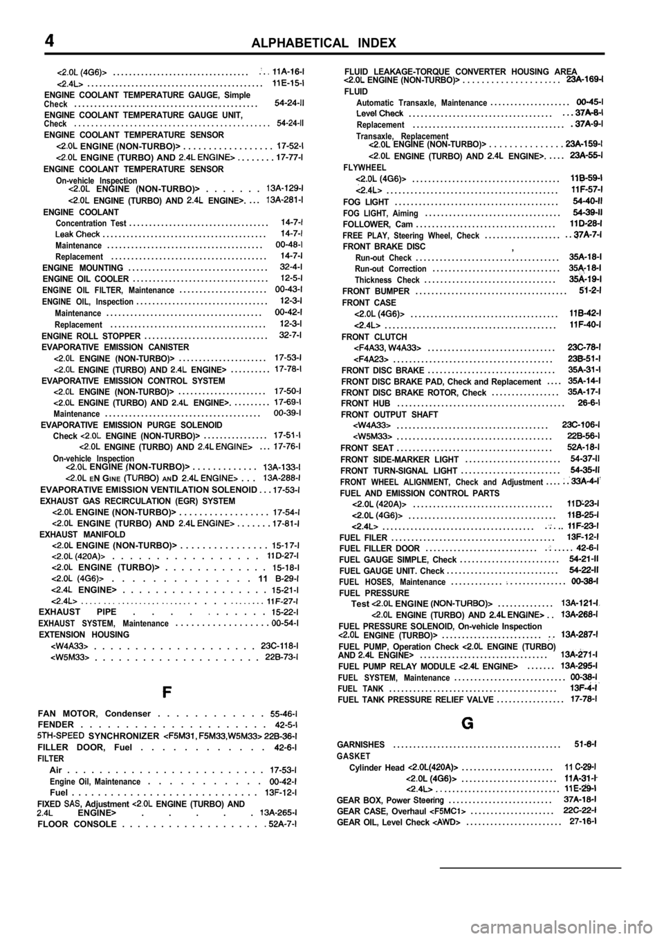
ALPHABETICAL INDEX
. . . . . . . . . . . . . . . . . . . . . . . . . . . . . . . . . ..
. . . . . . . . . . . . . . . . . . . . . . . . . . . . . . . . . . . . . . . . . . . .
ENGINE COOLANT TEMPERATURE GAUGE, SimpleCheck. . . . . . . . . . . . . . . . . . . . . . . . . . . . . . . . . . . . . . . . . . . . . .
ENGINE COOLANT TEMPERATURE GAUGE UNIT,Check. . . . . . . . . . . . . . . . . . . . . . . . . .
. . . . . . . . . . . . . . . . . . . .
ENGINE COOLANT TEMPERATURE SENSOR
ENGINE (NON-TURBO)> . . . . . . . . . . . . . . . . . .
ENGINE (TURBO) AND . . . . . . .
ENGINE COOLANT TEMPERATURE SENSOR
On-vehicle Inspection ENGINE (NON-TURBO)> . . . . . . .
ENGINE (TURBO) AND ENGINE>.. . .
ENGINE COOLANTConcentration Test. . . . . . . . . . . . . . . . . . . . . . . . . . . . . . . . . . .
. . . . . . . . . . . . . . . . . . . . . . . . . . . . . . . . . . . . . . . . .
Maintenance. . . . . . . . . . . . . . . . . . . . . . . . . . . . . . . . . . . . . . .
Replacement. . . . . . . . . . . . . . . . . . . . . . . . . . . . . . . . . . . . . . .
ENGINE MOUNTING. . . . . . . . . . . . . . . . . . . . . . . . . . . . . . . . . . .
ENGINE OIL COOLER. . . . . . . . . . . . . . . . . . . . . . . . . . . . . . . . . .
ENGINE OIL FILTER, Maintenance. . . . . . . . . . . . . . . . . . . . . .
ENGINE OIL, Inspection. . . . . . . . . . . . . . . . . . . . . . . . . . . . . . . . .
Maintenance. . . . . . . . . . . . . . . . . . . . . . . . . . . . . . . . . . . . . . .
Replacement. . . . . . . . . . . . . . . . . . . . . . . . . . . . . . . . . . . . . . .
ENGINE ROLL STOPPER. . . . . . . . . . . . . . . . . . . . . . . . . . . . . . .
EVAPORATIVE EMISSION CANISTER
ENGINE (NON-TURBO)>. . . . . . . . . . . . . . . . . . . . . .
ENGINE (TURBO) AND ENGINE>. . . . . . . . . .
EVAPORATIVE EMISSION CONTROL SYSTEM ENGINE (NON-TURBO)>. . . . . . . . . . . . . . . . . . . . . .
ENGINE (TURBO) AND ENGINE>.. . . . . . . . .
Maintenance. . . . . . . . . . . . . . . . . . . . . . . . . . . . . . . . . . . . . . .
EVAPORATIVE EMISSION PURGE SOLENOID
Check ENGINE (NON-TURBO)>. . . . . . . . . . . . . . . .
ENGINE (TURBO) AND . . .
On-vehicle Inspection ENGINE (NON-TURBO)> . . . . . . . . . . . . .
EN G INE AND . . .
EVAPORATIVE EMISSION VENTILATION SOLENOID . .
EXHAUST GAS RECIRCULATION (EGR) SYSTEM
ENGINE (NON-TURBO)> . . . . . . . . . . . . . . . . . .
ENGINE (TURBO) AND . . . . . . EXHAUST MANIFOLD ENGINE (NON-TURBO)> . . . . . . . . . . . . . . . . . . . . . . . . . . . . . . . . .
ENGINE (TURBO)> . . . . . . . . . . . . .
. . . . . . . . . . . . . . 11
ENGINE> . . . . . . . . . . . . . . . . . .
. . . . EXHAUST PIPE . . . . . . . . . .
EXHAUST SYSTEM, Maintenance. . . . . . . . . . . . . . . . . .
EXTENSION HOUSING
. . . . . . . . . . . . . . . . . . . .
. . . . . . . . . . . . . . . . . . . . .
FAN MOTOR, Condenser . . . . . . . . . . . . FENDER . . . . . . . . . . . . . . . . . . . . .
SYNCHRONIZER
FILLER DOOR, Fuel . . . . . . . . . . . .
FILTER
Air . . . . . . . . . . . . . . . . . . . . . . . . .
Engine Oil, Maintenance. . . . . . . . . . .
Fuel . . . . . . . . . . . . . . . . . . . . . . . . . . . . .
FIXED Adjustment ENGINE (TURBO) AND ENGINE> . . . . .
FLOOR CONSOLE . . . . . . . . . . . . . . . . . .
FLUID LEAKAGE-TORQUE CONVERTER HOUSING AREA ENGINE (NON-TURBO)> . . . . . . . . . . . . . . . . . . . .
FLUID
Automatic Transaxle, Maintenance. . . . . . . . . . . . . . . . . . . .
. . . . . . . . . . . . . . . . . . . . . . . . . . . . . . . . . . . .Replacement. . . . . . . . . . . . . . . . . . . . . . . . . . . . . . . . . . . . . .
Transaxle, Replacement ENGINE (NON-TURBO)> . . . . . . . . . . . . . . .
ENGINE (TURBO) AND ENGINE>.. . . .
FLYWHEEL
. . . . . . . . . . . . . . . . . . . . . . . . . . . . . . . . . . . . .
. . . . . . . . . . . . . . . . . . . . . . . . . . . . . . . . . . . . . . . . . . .
FOG LIGHT. . . . . . . . . . . . . . . . . . . . . . . . . . . . . . . . . . . . . . . . .
FOG LIGHT, Aiming. . . . . . . . . . . . . . . . . . . . . . . . . . . . . . . . . .
FOLLOWER, Cam. . . . . . . . . . . . . . . . . . . . . . . . . . . . . . . . . . .
FREE PLAY, Steering Wheel, Check. . . . . . . . . . . . . . . . . . .
FRONT BRAKE DISC,Run-out Check. . . . . . . . . . . . . . . . . . . . . . . . . . . . . . . . . . . .Run-out Correction. . . . . . . . . . . . . . . . . . . . . . . . . . . . . . . .
Thickness Check. . . . . . . . . . . . . . . . . . . . . . . . . . . . . . . . .
FRONT BUMPER. . . . . . . . . . . . . . . . . . . . . . . . . . . . . . . . . . . . . .
FRONT CASE
. . . . . . . . . . . . . . . . . . . . . . . . . . . . . . . . . . . . .
. . . . . . . . . . . . . . . . . . . . . . . . . . . . . . . . . . . . . . . . . . .
FRONT CLUTCH. . . . . . . . . . . . . . . . . . . . . . . . . . . . . . . .
. . . . . . . . . . . . . . . . . . . . . . . . . . . . . . . . . . . . . . . .FRONT DISC BRAKE. . . . . . . . . . . . . . . . . . . . . . . . . . . . . . . .
FRONT DISC BRAKE PAD, Check and Replacement. . . .
FRONT DISC BRAKE ROTOR, Check. . . . . . . . . . . . . . . . .FRONT HUB. . . . . . . . . . . . . . . . . . . . . . . . . . . . . . . . . . . . . . . . . .
FRONT OUTPUT SHAFT. . . . . . . . . . . . . . . . . . . . . . . . . . . . . . . . . . . . . .. . . . . . . . . . . . . . . . . . . . . . . . . . . . . . . . . . . . . . .
FRONT SEAT. . . . . . . . . . . . . . . . . . . . . . . . . . . . . . . . . . . . . . .
FRONT SIDE-MARKER LIGHT. . . . . . . . . . . . . . . . . . . . . . . .
FRONT TURN-SIGNAL LIGHT. . . . . . . . . . . . . . . . . . . . . . . . .
FRONT WHEEL ALIGNMENT, Check and Adjustment. . . .
FUEL AND EMISSION CONTROL PARTS. . . . . . . . . . . . . . . . . . . . . . . . . . . . . . . . . . .
. . . . . . . . . . . . . . . . . . . . . . . . . . . . . . . . . . . . .. . . . . . . . . . . . . . . . . . . . . . . . . . . . . . . . . . . . . ...
FUEL FILER. . . . . . . . . . . . . . . . . . . . . . . . . . . . . . . . . . . . . . . . .FUEL FILLER DOOR. . . . . . . . . . . . . . . . . . . . . . . . . . . .. . . . .
FUEL GAUGE SIMPLE, Check. . . . . . . . . . . . . . . . . . . . . . . . .
FUEL GAUGE UNIT. Check. . . . . . . . . . . . . . . . . . . . . . . . . . . .
FUEL HOSES, Maintenance. . . . . . . . . . . . .. . . . . . . . . . . . .
FUEL PRESSURETest ENGINE . . . . . . . . . . . . . .
ENGINE (TURBO) AND . .
FUEL PRESSURE SOLENOID, On-vehicle Inspection ENGINE (TURBO)>. . . . . . . . . . . . . . . . . . . . . . . . .
FUEL PUMP, Operation Check ENGINE (TURBO)
AND ENGINE>. . . . . . . . . . . . . . . . . . . . . . . . . . . . . . . .
FUEL PUMP RELAY MODULE ENGINE>. . . . . . .
FUEL SYSTEM, Maintenance. . . . . . . . . . . . . . . . . . . . . . . . . . . .
FUEL TANK. . . . . . . . . . . . . . . . . . . . . . . . . . . . . . . . . . . . . . . . . .FUEL TANK PRESSURE RELIEF VALVE. . . . . . . . . . . . . . . . .
GARNISHES. . . . . . . . . . . . . . . . . . . . . . . . . . . . . . . . . . . . . . . . . .
GASKET
Cylinder Head . . . . . . . . . . . . . . . . . . . . . . .11
. . . . . . . . . . . . . . . . . . . . . . . .. . . . . . . . . . . . . . . . . . . . . . . . . . . . .
GEAR BOX, Power . . . . . . . . . . . . . . . . . . . . . . . . . .
GEAR CASE, Overhaul . . . . . . . . . . . . . . . . . . . . .
GEAR OIL, Level Check . . . . . . . . . . . . . . . . . . . . . . . .