torque MITSUBISHI SPYDER 1990 Service Repair Manual
[x] Cancel search | Manufacturer: MITSUBISHI, Model Year: 1990, Model line: SPYDER, Model: MITSUBISHI SPYDER 1990Pages: 2103, PDF Size: 68.98 MB
Page 1612 of 2103
FRONT SUSPENSION
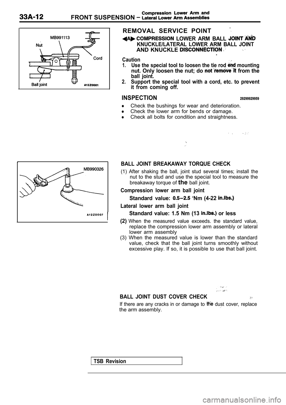
REMOVAL SERVICE POINT
LOWER ARM BALL
KNUCKLE/LATERAL LOWER ARM BALL JOINT
AND KNUCKLE .
Caution
1.Use the special tool to loosen the tie rod mounting
nut. Only loosen the nut; do from the
ball joint.
2.Support the special tool with a cord, etc. to prevent
it from coming off.
INSPECTION29299929959
lCheck the bushings for wear and deterioration.
lCheck the lower arm for bends or damage.
lCheck all bolts for condition and straightness.
BALL JOINT BREAKAWAY TORQUE CHECK
(1) After shaking the ball, joint stud several time s; install the
nut to the stud and use the special tool to measure the
breakaway torque of theball joint.
Compression lower arm ball joint
Standard value: ‘Nm (4-22
Lateral lower arm ball joint
Standard value: 1.5 Nm (13 or less
(2)
When the measured value exceeds. the standard value ,
replace the compression lower arm assembly or lateral
lower arm assembly
(3) When the measured value is lower than the stand ard
value, check that the ball joint turns smoothly wit hout
excessive play. If so, it is possible to use that b all joint.
BALL JOINT DUST COVER CHECK
If there are any cracks in or damage to dust cover, replace
the arm assembly.
TSB Revision
Page 1615 of 2103
FRONT SUSPENSION , ,
Al
Clip ring ends onopposite side also possible)
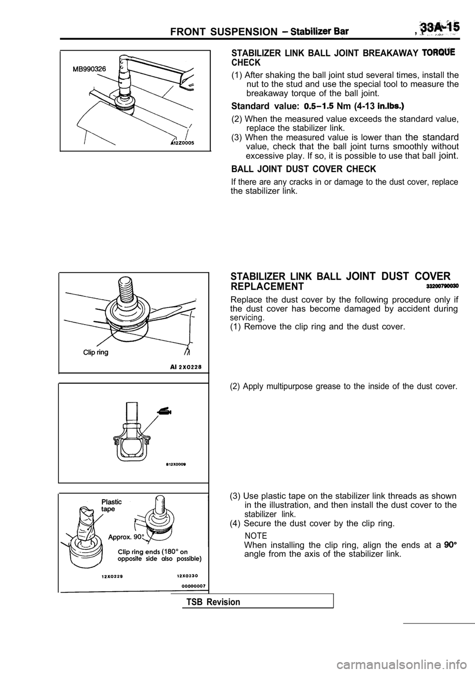
STABILIZER LINK BALL JOINT BREAKAWAY
CHECK
(1) After shaking the ball joint stud several times, install the
nut to the stud and use the special tool to measure the
breakaway torque of the ball joint.
Standard value: Nm (4-13
(2) When the measured value exceeds the standard va lue,
replace the stabilizer link.
(3) When the measured value is lower than the standard
value, check that the ball joint turns smoothly wit hout
excessive play. If so, it is possible to use that b all joint.
BALL JOINT DUST COVER CHECK
If there are any cracks in or damage to the dust co ver, replace
the stabilizer link.
STABILIZER LINK BALL JOINT DUST COVER
REPLACEMENT
Replace the dust cover by the following procedure o nly if
the dust cover has become damaged by accident durin g
servicing.
(1) Remove the clip ring and the dust cover.
(2) Apply multipurpose grease to the inside of the dust cover.
(3) Use plastic tape on the stabilizer link threads as shown
in the illustration, and then install the dust cove r to the
stabilizer link.
(4) Secure the dust cover by the clip ring.
NOTE
When installing the clip ring, align the ends at a
angle from the axis of the stabilizer link.
TSB Revision
Page 1620 of 2103
REAR SUSPENSION Service Specifications/Special tools, , .
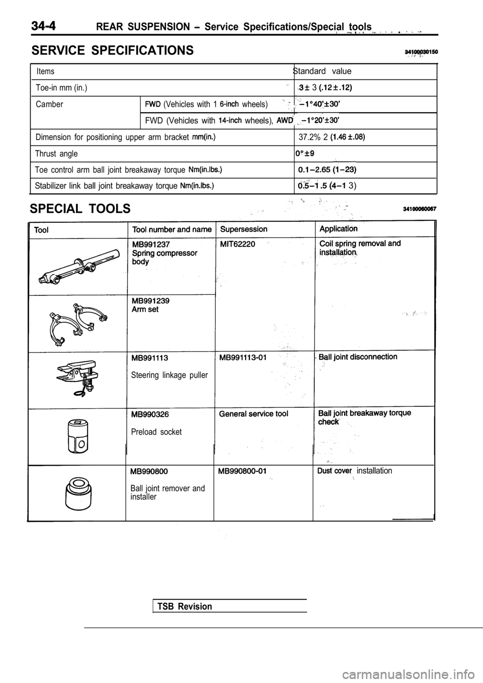
SERVICE SPECIFICATIONS
Items
Toe-in mm (in.)
Standard value
3
Camber (Vehicles with 1 wheels)
FWD (Vehicles with wheels),
Dimension for positioning upper arm bracket
Thrust angle
Toe control arm ball joint breakaway torque
Stabilizer link ball joint breakaway torque
SPECIAL TOOLS
37.2% 2
3)
Steering linkage puller
Preload socket
.
installation
Ball joint remover and
installer
TSB Revision
Page 1629 of 2103
REAR SUSPENSION Lower Arm and Toe Control Arm Assemblies
Toe controlarm sideEccentric
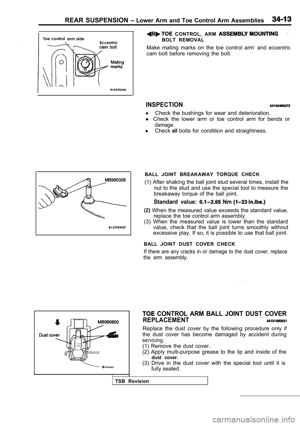
CONTROL, ARM
BOLT REMOVAL
Make mating marks on the toe control arm’ and eccen tric
cam bolt before removing the bolt.
INSPECTION
lCheck the bushings for wear and deterioration.
l Check the lower arm or toe control arm for bends or
damage.
lCheck bolts for condition and straightness.
BALL JOINT BREAKAWAY TORQUE CHECK
(1) After shaking the ball joint stud several times , install the
nut to the stud and use the special tool to measure the
breakaway torque of the ball joint.
Standard value: Nm
When the measured value exceeds the standard value ,
replace the toe control arm assembly.
(3) When the measured value is lower than the stand ard
value, check that the ball joint turns smoothly wit hout
excessive play. If so, it is possible to use that b all joint.
BALL JOINT DUST COVER CHECK
If there are any cracks in or damage to the dust co ver, replace
the arm assembly.
CONTROL ARM BALL JOINT DUST COVER
REPLACEMENT
Replace the dust cover by the following procedure o nly if
the dust cover has become damaged by accident durin g
servicing.
(1) Remove the dust cover.
(2) Apply multi-purpose grease to the lip and insid e of the
dust cover.
(3) Drive in the dust cover with the special tool u ntil it is
fully seated.
TSB Revision
Page 1634 of 2103
S U S P E N S I O N B a r
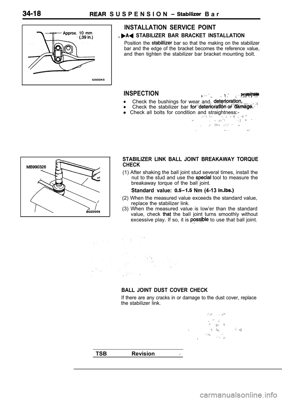
INSTALLATION SERVICE POINT
, STABILIZER BAR BRACKET INSTALLATION
Position the bar so that the making on the stabilizer
bar and the edge of the bracket becomes the referen ce value,
and then tighten the stabilizer bar bracket mounting bolt.
INSPECTION,
lCheck the bushings for wear and,
lCheck the stabilizer bar
l Check all bolts for condition and straightness:- .
. . ,
STABILIZER LINK BALL JOINT BREAKAWAY TORQUE
CHECK
(1) After shaking the ball joint stud several times , install the
nut to the stud and use the
tool to measure the
breakaway torque of the ball joint.
Standard value: Nm (4-13
(2) When the measured value exceeds the standard va lue,
replace the stabilizer link.
(3) When the measured value is low’er than the stan dard
value, check
the ball joint turns smoothly without
excessive play. If so, it is
to use that ball joint.
BALL JOINT DUST COVER CHECK
If there are any cracks in or damage to the dust co ver, replace
the stabilizer link.
TSB Revision
Page 1653 of 2103
BASIC BRAKE SYSTEM
Front hub assembly
196-255 Nm
145-188
3.
4.
5.
6.
8.
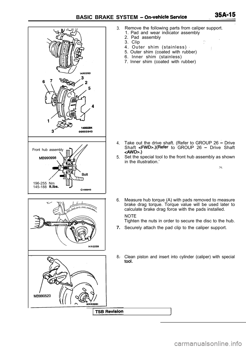
Remove the following parts from caliper support. 1. Pad and wear indicator assembly
2. Pad assembly
3. Clip
4 . O u t e r s h i m ( s t a i n l e s s )
5. Outer shim (coated with rubber)
6. Inner shim (stainless)
7. Inner shim (coated with rubber)
Take out the drive shaft. (Refer to GROUP 26
Drive
Shaft
to GROUP 26 Drive Shaft
Set the special tool to the front hub assembly as s hown
in the illustration.’
Measure hub torque (A) with pads removed to measure
brake drag torque. Torque value will be used later to
calculate brake drag force with the pads installed.
NOTE
Tighten the nuts in order to secure the disc to the hub.
Securely attach the pad clip to the caliper support .
Clean piston and insert into cylinder (caliper) with special
Page 1654 of 2103
BASIC BRAKE SYSTEM On-vehicle Service
Pad assembly
Grease
Grease Al
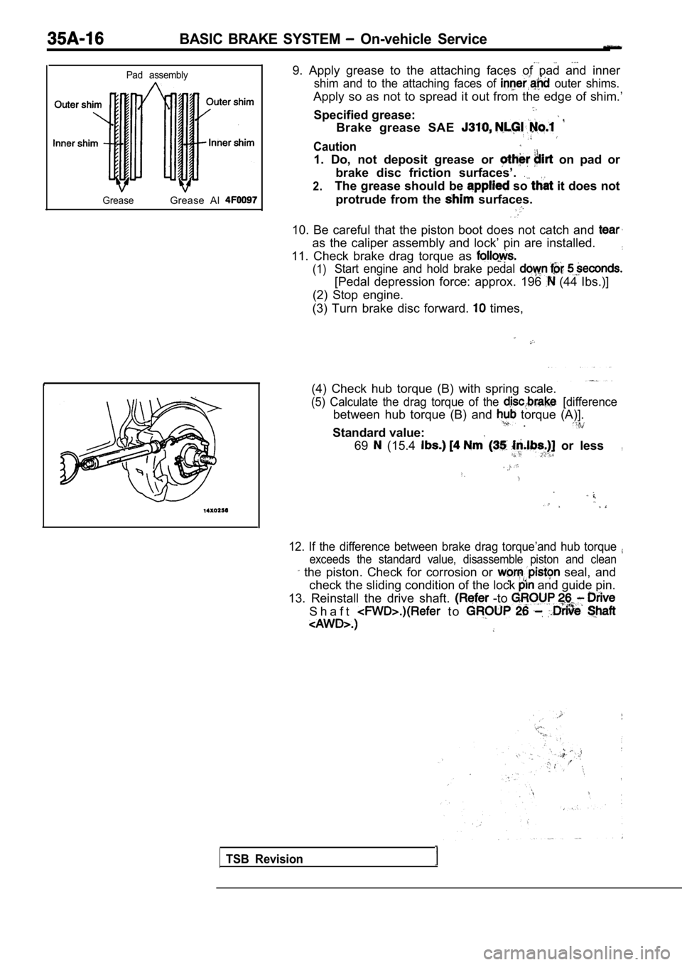
9. Apply grease to the attaching faces of pad and i nner
shim and to the attaching faces of outer shims.
Apply so as not to spread it out from the edge of shim.’
Specified grease:
Brake grease SAE
Caution
1. Do, not deposit grease or on pad or
brake disc friction surfaces’.
2.The grease should be so it does not
protrude from the
surfaces.
10. Be careful that the piston boot does not catch and
as the caliper assembly and lock’ pin are installed.
11. Check brake drag torque as
(1)Start engine and hold brake pedal
[Pedal depression force: approx. 196 (44 Ibs.)]
(2) Stop engine.
(3) Turn brake disc forward.
times,
(4) Check hub torque (B) with spring scale.
(5) Calculate the drag torque of the [difference
between hub torque (B) and torque (A)]. .
Standard value:
69 (15.4 or less,
12. If the difference between brake drag torque’and hub torque
exceeds the standard value, disassemble piston and clean
the piston. Check for corrosion or seal, and
check the sliding condition of the lock
and guide pin.
13. Reinstall the drive shaft.
-to
S h a f t t o
TSB Revision
Page 1660 of 2103
BASIC BRAKE SYSTEM On-vehicle Service
TSB Revision
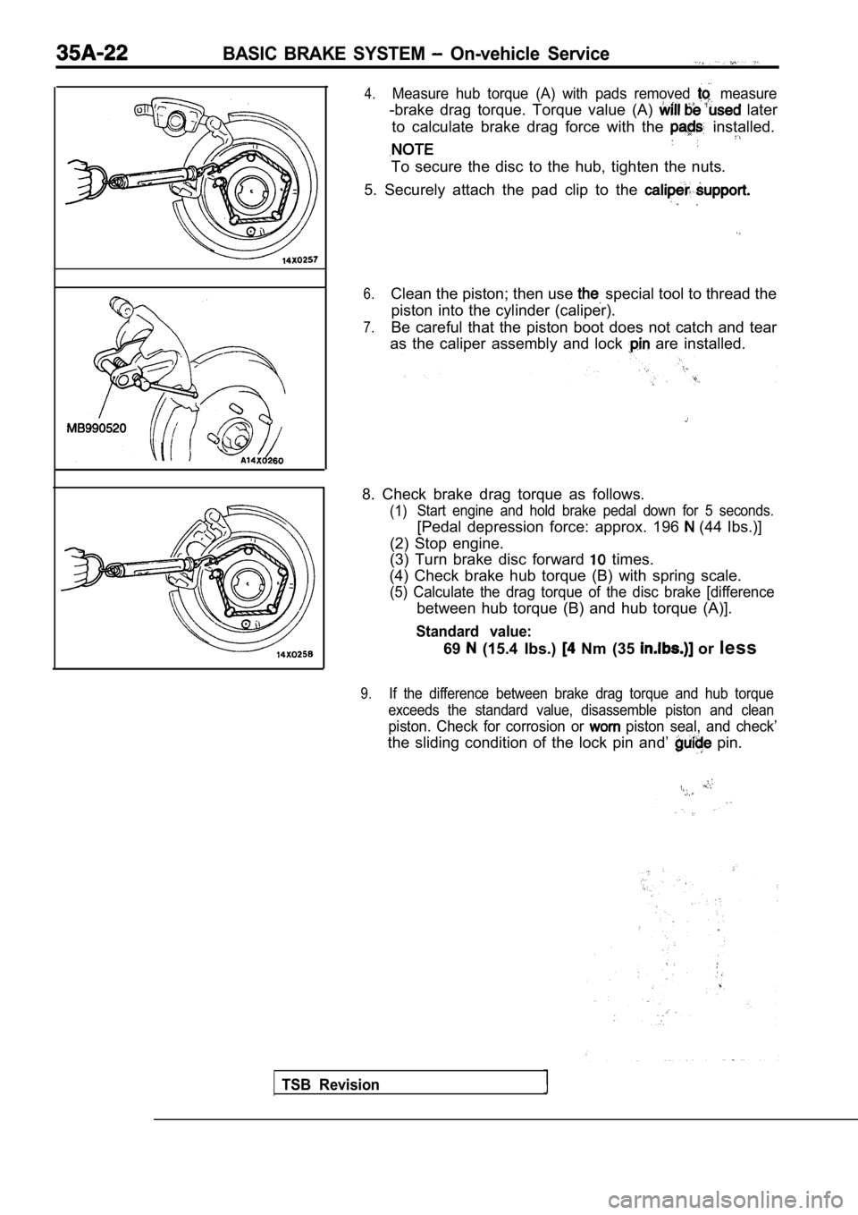
4.Measure hub torque (A) with pads removed measure
-brake drag torque. Torque value (A) later
to calculate brake drag force with the
installed.
To secure the disc to the hub, tighten the nuts.
5. Securely attach the pad clip to the
6.Clean the piston; then use special tool to thread the
piston into the cylinder (caliper).
7.Be careful that the piston boot does not catch and tear
as the caliper assembly and lock
are installed.
8. Check brake drag torque as follows.
(1) Start engine and hold brake pedal down for 5 second
s.
[Pedal depression force: approx. 196 (44 Ibs.)]
(2) Stop engine.
(3) Turn brake disc forward
times.
(4) Check brake hub torque (B) with spring scale.
(5) Calculate the drag torque of the disc brake [di fference
between hub torque (B) and hub torque (A)].
Standard value:
69 (15.4 Ibs.) Nm (35 or less
9.If the difference between brake drag torque and hub torque
exceeds the standard value, disassemble piston and clean
piston. Check for corrosion or piston seal, and check’
the sliding condition of the lock pin and’ pin.
Page 1669 of 2103
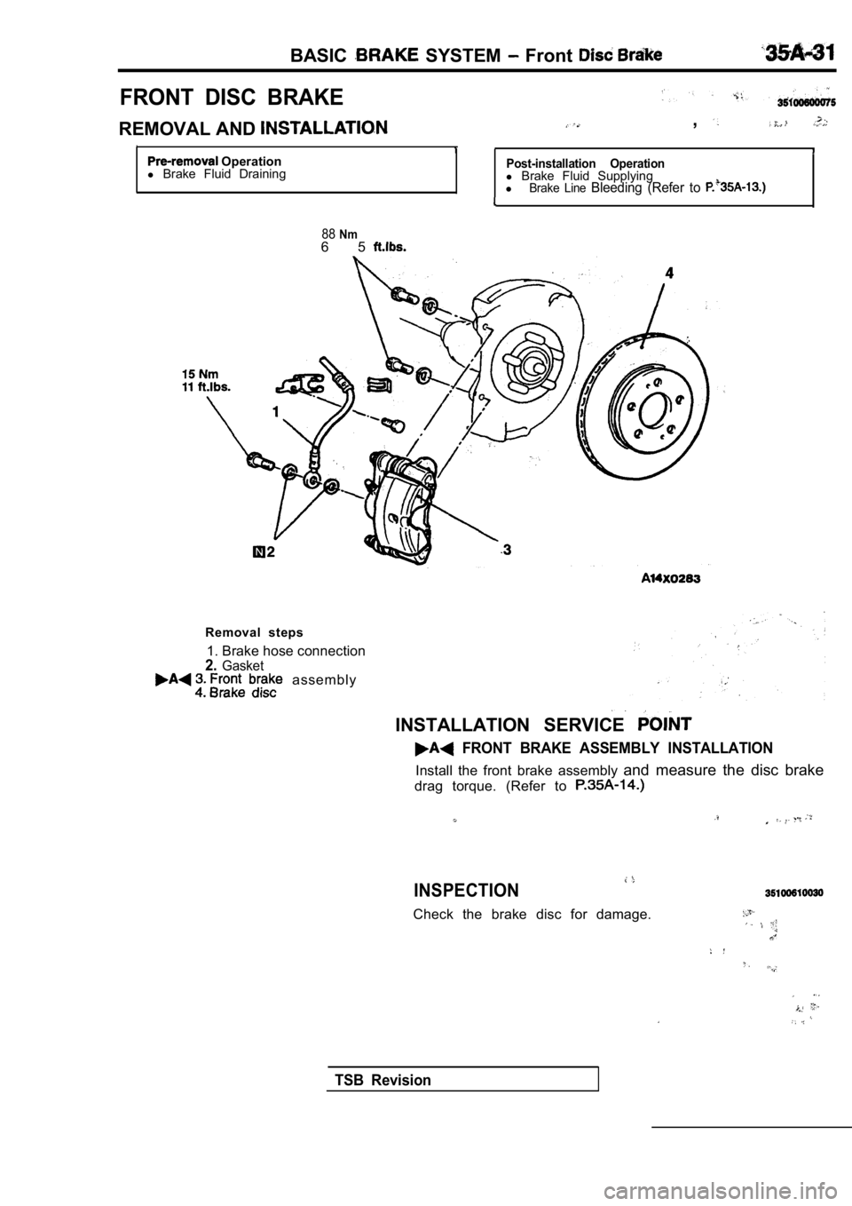
BASIC SYSTEM Front
FRONT DISC BRAKE
REMOVAL AND ,
I1I Operation
l Brake Fluid DrainingPost-installation Operationl Brake Fluid Supplying
lBrake Line Bleeding (Refer to
I
88Nm6 5
Removal steps
1. Brake hose connection
2.Gasket assembly
INSTALLATION SERVICE
FRONT BRAKE ASSEMBLY INSTALLATION
Install the front brake assembly and measure the disc brake
drag torque. (Refer to
INSPECTION
Check the brake disc for damage.
TSB Revision
Page 1683 of 2103
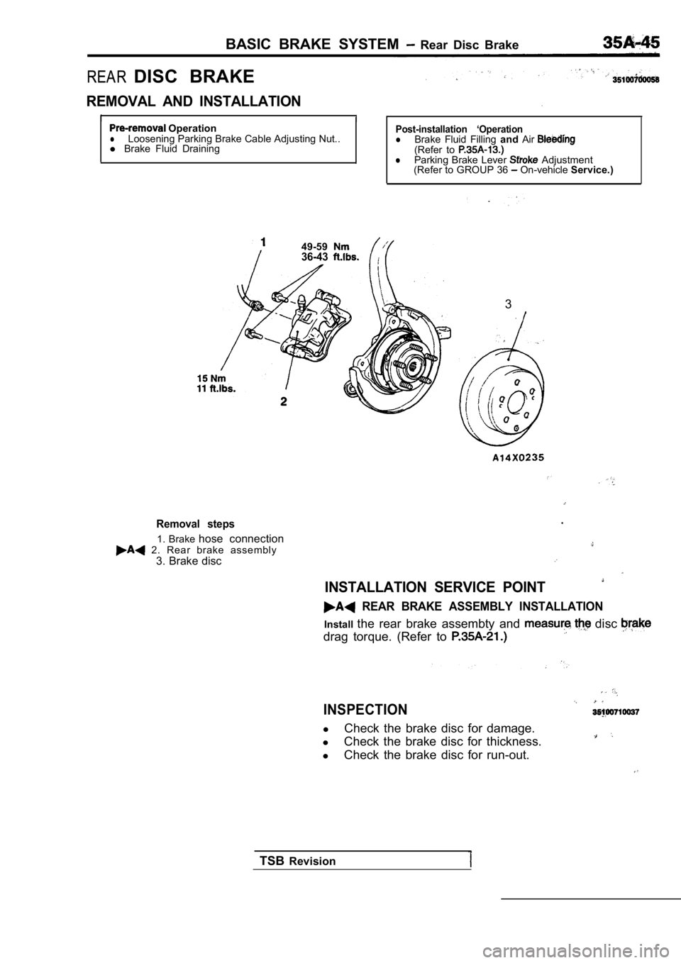
BASIC BRAKE SYSTEM Rear Disc Brake
REAR DISC BRAKE
REMOVAL AND INSTALLATION
I
I OperationlLoosening Parking Brake Cable Adjusting Nut..
l Brake Fluid DrainingPost-installation ‘OperationlBrake Fluid Filling andAir(Refer to lParking Brake Lever Adjustment
(Refer to GROUP 36 On-vehicle Service.)
49-59
36-43
3
Removal steps
1. Brake hose connection 2. Rear brake assembly
3. Brake disc .
INSTALLATION SERVICE POINT
REAR BRAKE ASSEMBLY INSTALLATION
Install
the rear brake assembty and disc
drag torque. (Refer to
INSPECTION
lCheck the brake disc for damage.
l Check the brake disc for thickness.
l Check the brake disc for run-out.
TSB Revision