torque MITSUBISHI SPYDER 1990 Service Repair Manual
[x] Cancel search | Manufacturer: MITSUBISHI, Model Year: 1990, Model line: SPYDER, Model: MITSUBISHI SPYDER 1990Pages: 2103, PDF Size: 68.98 MB
Page 1469 of 2103

AUTOMATIC TRANSAXLE OVERHAUL Valve Body
T/C control valve
spring plug
Regulator
valve spring
76
r e t a i n e r p l a t e w i t h
6.
Remove torque converter control valve and torque
converter clutch valve.
retainer
plateusingInstaller/Remover
17.
(15) Remove
Removeregulator valve.
TSB Revision
Page 1470 of 2103
AUTOMATIC TRANSAXLE OVERHAUL Valve Body
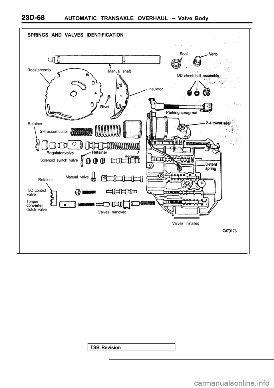
SPRINGS AND VALVES IDENTIFICATION
Roostercomb.Manual shaft
Retainer
-4
Rivet
Solenoid switch valve
Retainer
T/C control
valve
Torque
clutch valve Manual valve
Insulator
check ball
accumulator
Valves removed
TSB Revision
Valves installed
76
Page 1471 of 2103
AUTOMATIC TRANSAXLE OVERHAUL Body
Retainer
Check ball
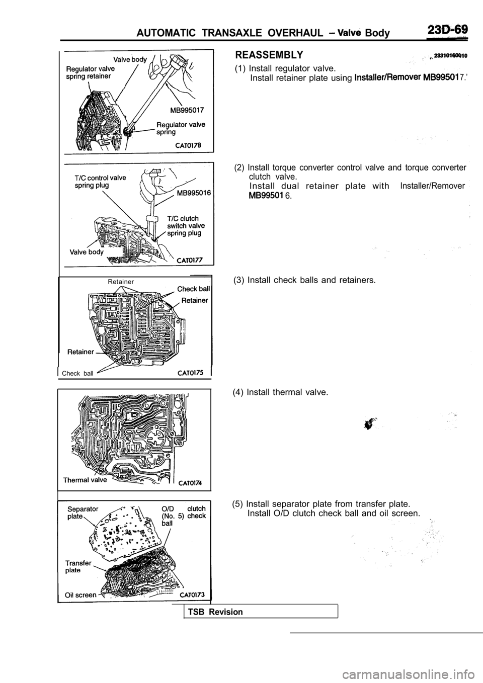
REASSEMBLY
(1) Install regulator valve.Install retainer plate using
7.’
(2) Install torque converter control valve and torq ue converter
clutch valve.
Install dual retainer plate withInstaller/Remover
6.
(3) Install check balls and retainers.
(4) Install thermal valve.
(5) Install separator plate from transfer plate. Install O/D clutch check ball and oil screen.
TSB Revision
Page 1483 of 2103
TRANSAXLE OVERHAUL Differential
Dial indicator
bracket
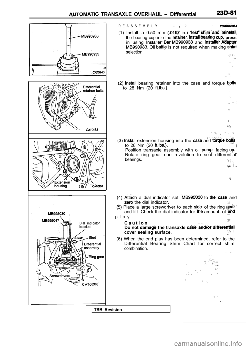
R E A S S E M B L Y
(1) Install ‘a 0.50 mm in.)
the bearing cup into the press
in using and
Oil is not required when making
selection.
(2) bearing retainer into the case and torque
to 28 Nm (20
.
,(3) extension housing into the and
to 28 Nm (20
Position transaxle assembly with oil facing
Rotate ring gear one revolution to seal differentia l’
bearings.
I,.
(4) a dial indicator set to and
the dial indicator., Place a large screwdriver to each of the ring
and lift. Check the dial indicator for amount- of
p l a y .
C a u t i o n
Do not
the transaxle
cover sealing surface.
TSB Revision
(6) When the end play has been determined, refer to the
Differential Bearing Shim Chart for correct shim
combination.__
Page 1486 of 2103
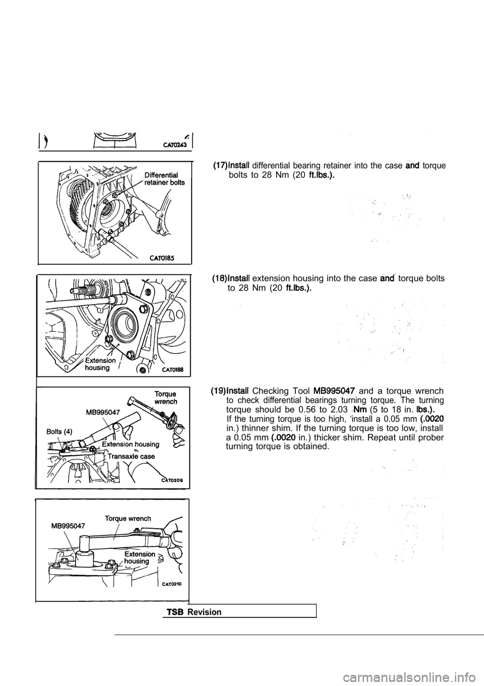
differential bearing retainer into the case torque
bolts to 28 Nm (20
extension housing into the case torque bolts
to 28 Nm (20
Checking Tool and a torque wrench
to check differential bearings turning torque. The turning
torque should be 0.56 to 2.03 (5 to 18 in.
If the turning torque is too high, ‘install a 0.05 mm
in.) thinner shim. If the turning torque is too low , install
a 0.05 mm
in.) thicker shim. Repeat until prober
turning torque is obtained.
Revision
Page 1488 of 2103
AUTOMATIC TRANSAXLE OVERHAUL Differential
Side gear thrust
w as h er
Was h er
Pinion
Ham m er
case
tc
Torque wench
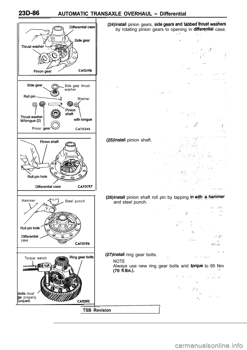
pinion gears,
by rotating pinion gears to opening in case.
must properly
pinion shaft.
, St eel p u n c h
pinion shaft roll pin by tapping
and steel punch.
. , ring gear bolts.
NOTE
Always use new ring gear bolts arid to 95 Nm
(70
.
TSB Revision
Page 1506 of 2103
GENERAL INFORMATION
FRONT AXLE General Specification/Lubricants
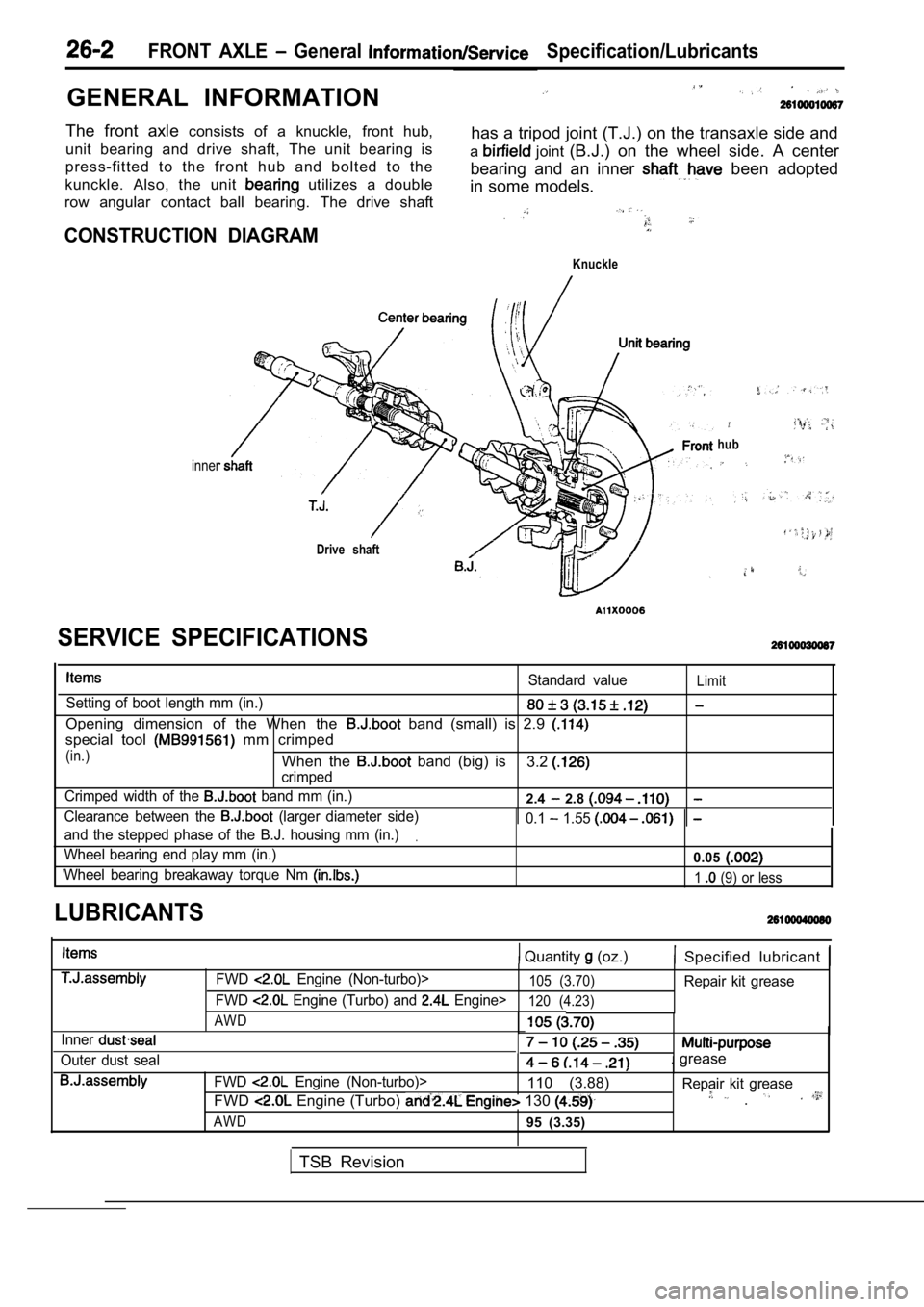
The front axle consists of a knuckle, front hub,
unit bearing and drive shaft, The unit bearing is has a tripod joint (T.J.) on the transaxle side and
press-fitted to the front hub and bolted to the a
joint
(B.J.) on the wheel side. A center
kunckle. Also, the unit
utilizes a double bearing and an inner been adopted
in some models.
row angular contact ball bearing. The drive shaft
CONSTRUCTION DIAGRAM
Knuckle
inner
Drive shaft
hub
Standard valueLimit
Setting of boot length mm (in.)
Opening dimension of the When the band (small) is 2.9
special tool mm crimped
(in.)When the band (big) is
crimped3.2
Crimped width of the band mm (in.)2.4 2.8
Clearance between the (larger diameter side) 0.1 1.55
and the stepped phase of the B.J. housing mm (in.).
Wheel bearing end play mm (in.)0.05
Wheel bearing breakaway torque Nm 1 (9) or less
SERVICE SPECIFICATIONS
LUBRICANTS
Quantity (oz.) Specified lubricant
Inner
Outer dust sealFWD
Engine (Non-turbo)>105 (3.70)Repair kit grease
FWD
Engine (Turbo) and Engine>120 (4.23)
AWD
. grease
FWD Engine (Non-turbo)>110 (3.88) Repair kit grease
FWD Engine (Turbo) 130 .
AWD95 (3.35)
TSB Revision
Page 1507 of 2103
SPECIAL TOOLS
FRONT AXLE Special , . . .
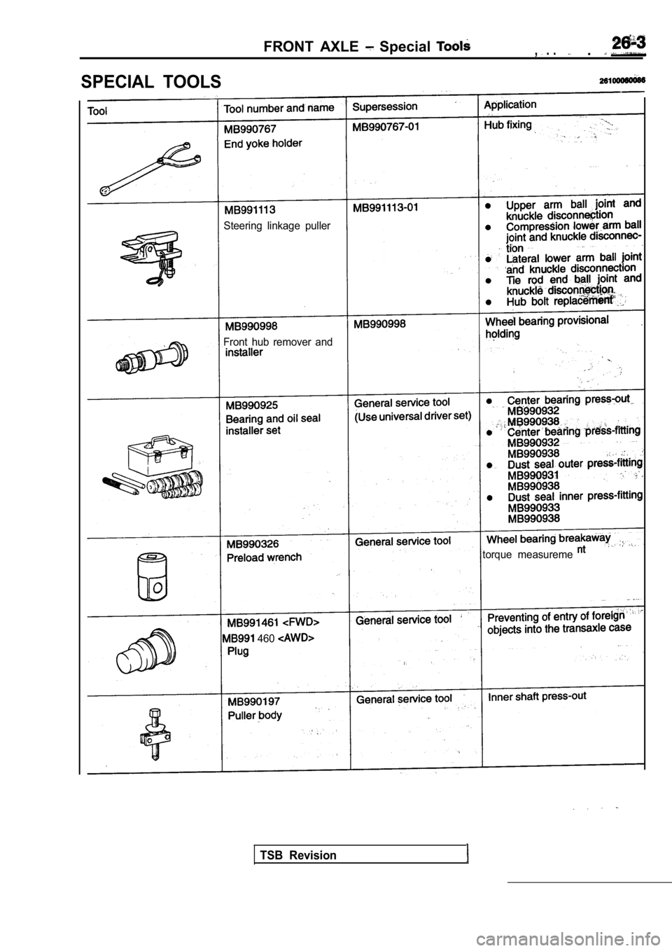
Steering linkage puller
Front hub remover and
torque measureme
460
TSB Revision
Page 1511 of 2103
FRONT AXLE Front Hub Assembly
196-255 Nm
145-188
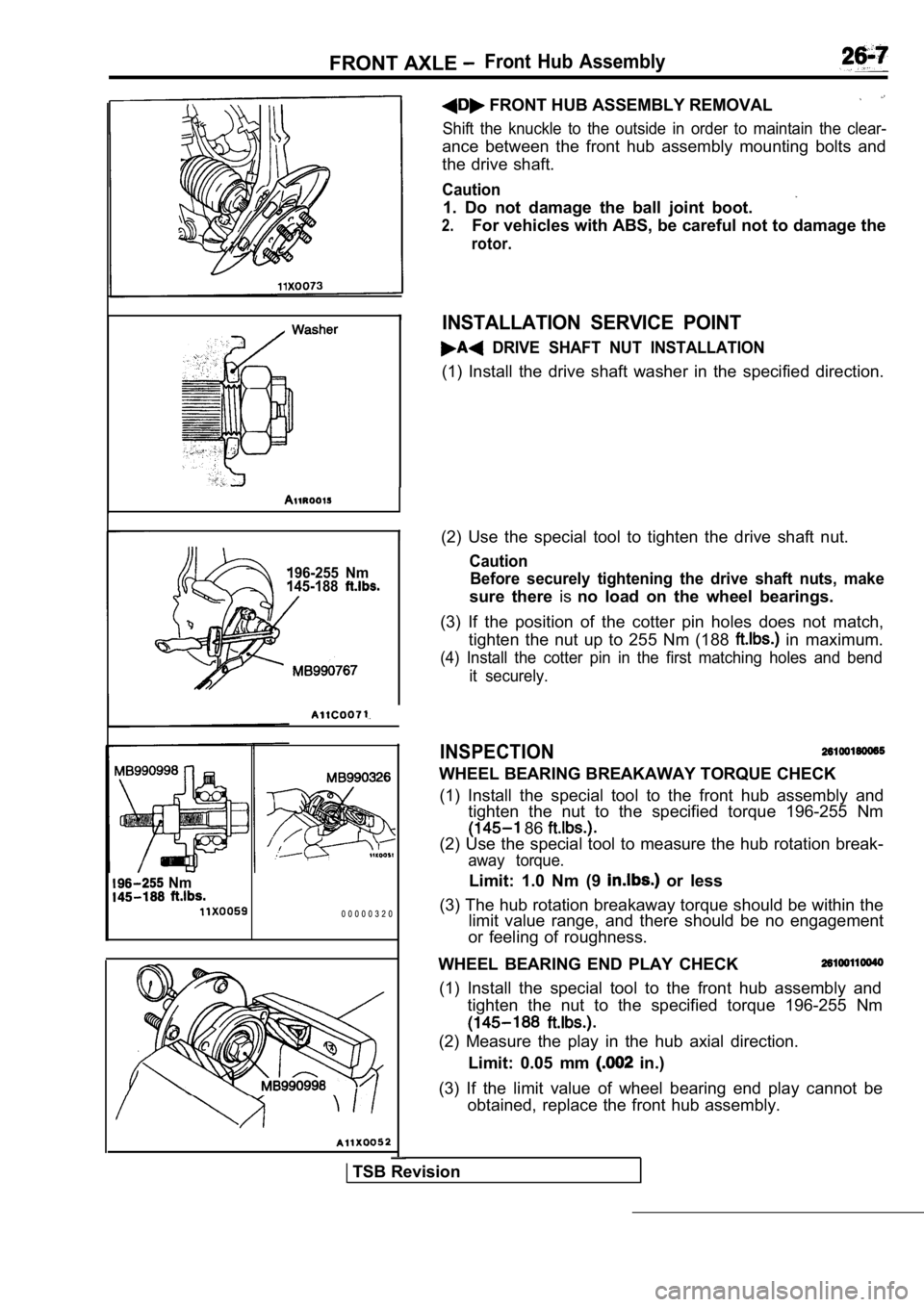
I(2) Use the special tool to tighten the drive shaft nut.
Caution
Before securely tightening the drive shaft nuts, ma ke
sure there isno load on the wheel bearings.
(3) If the position of the cotter pin holes does no t match,
tighten the nut up to 255 Nm (188
in maximum.
(4) Install the cotter pin in the first matching ho les and bend
it securely.
INSPECTION
WHEEL BEARING BREAKAWAY TORQUE CHECK
(1) Install the special tool to the front hub assem bly and
tighten the nut to the specified torque 196-255 Nm
86
(2) Use the special tool to measure the hub rotatio n break-
away torque.
Limit: 1.0 Nm (9 or less
(3) The hub rotation breakaway torque should be wit hin the
limit value range, and there should be no engagemen t
or feeling of roughness. Nm
0 0 0 0 0 3 2 0
FRONT HUB ASSEMBLY REMOVAL
Shift the knuckle to the outside in order to mainta in the clear-
ance between the front hub assembly mounting bolts and
the drive shaft.
Caution
1. Do not damage the ball joint boot.
2.For vehicles with ABS, be careful not to damage the
rotor.
INSTALLATION SERVICE POINT
DRIVE SHAFT NUT INSTALLATION
(1) Install the drive shaft washer in the specified direction.
WHEEL BEARING END PLAY CHECK
(1) Install the special tool to the front hub assem bly and
tighten the nut to the specified torque 196-255 Nm
(2) Measure the play in the hub axial direction.
Limit: 0.05 mm
in.)
(3) If the limit value of wheel bearing end play ca nnot be
obtained, replace the front hub assembly.
TSB Revision
Page 1553 of 2103
REAR AXLE Rear Assembly
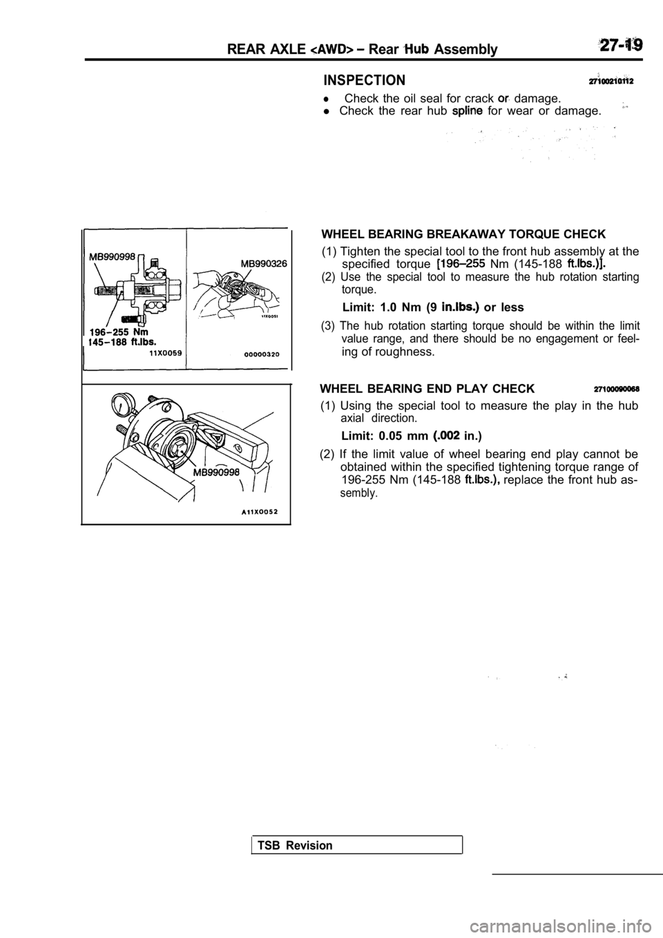
INSPECTION
lCheck the oil seal for crack damage.
l Check the rear hub
for wear or damage.
WHEEL BEARING BREAKAWAY TORQUE CHECK
(1) Tighten the special tool to the front hub assem bly at the
specified torque
Nm (145-188
(2) Use the special tool to measure the hub rotatio n starting
torque.
Limit: 1.0 Nm (9 or less
(3) The hub rotation starting torque should be with in the limit
value range, and there should be no engagement or f eel-
ing of roughness.
WHEEL BEARING END PLAY CHECK
(1) Using the special tool to measure the play in t he hub
axial direction.
Limit: 0.05 mm in.)
(2) If the limit value of wheel bearing end play ca nnot be
obtained within the specified tightening torque ran ge of
196-255 Nm (145-188
replace the front hub as-
sembly.
TSB Revision